EP1097656B1 - Tischart welche mit mindestens einem faltbaren Fuss oder Untergestell versehen ist - Google Patents
Tischart welche mit mindestens einem faltbaren Fuss oder Untergestell versehen ist Download PDFInfo
- Publication number
- EP1097656B1 EP1097656B1 EP00460059A EP00460059A EP1097656B1 EP 1097656 B1 EP1097656 B1 EP 1097656B1 EP 00460059 A EP00460059 A EP 00460059A EP 00460059 A EP00460059 A EP 00460059A EP 1097656 B1 EP1097656 B1 EP 1097656B1
- Authority
- EP
- European Patent Office
- Prior art keywords
- foot
- base
- table according
- unfolded
- folded
- Prior art date
- Legal status (The legal status is an assumption and is not a legal conclusion. Google has not performed a legal analysis and makes no representation as to the accuracy of the status listed.)
- Expired - Lifetime
Links
- 235000004443 Ricinus communis Nutrition 0.000 claims 1
- 240000000528 Ricinus communis Species 0.000 claims 1
- 230000000903 blocking effect Effects 0.000 description 7
- 125000006850 spacer group Chemical group 0.000 description 4
- 238000010276 construction Methods 0.000 description 2
- 238000006073 displacement reaction Methods 0.000 description 2
- 241000920340 Pion Species 0.000 description 1
- 239000004566 building material Substances 0.000 description 1
- 230000000284 resting effect Effects 0.000 description 1
Images

Classifications
-
- A—HUMAN NECESSITIES
- A47—FURNITURE; DOMESTIC ARTICLES OR APPLIANCES; COFFEE MILLS; SPICE MILLS; SUCTION CLEANERS IN GENERAL
- A47B—TABLES; DESKS; OFFICE FURNITURE; CABINETS; DRAWERS; GENERAL DETAILS OF FURNITURE
- A47B3/00—Folding or stowable tables
- A47B3/08—Folding or stowable tables with legs pivoted to top or underframe
- A47B3/0809—Folding or stowable tables with legs pivoted to top or underframe with elastic locking means
- A47B3/0815—Folding or stowable tables with legs pivoted to top or underframe with elastic locking means the resilient force of the elastic locking means acting in a direction perpendicular to the axis of rotation of the leg
-
- A—HUMAN NECESSITIES
- A47—FURNITURE; DOMESTIC ARTICLES OR APPLIANCES; COFFEE MILLS; SPICE MILLS; SUCTION CLEANERS IN GENERAL
- A47B—TABLES; DESKS; OFFICE FURNITURE; CABINETS; DRAWERS; GENERAL DETAILS OF FURNITURE
- A47B3/00—Folding or stowable tables
- A47B3/08—Folding or stowable tables with legs pivoted to top or underframe
- A47B2003/0824—Folding or stowable tables with legs pivoted to top or underframe the table legs being individually collapsible against the underside of the table top
Definitions
- the present invention relates to a table of the type having at least one foot or foldable frame mounted on a frame.
- a table can have various applications and, in particular, that of supporting tools such as saws Circular used in the field of building.
- Tables are known whose table legs are collapsible to obtain a less space of said tables during their transport and to facilitate their set up on construction sites.
- US-A-4,144,822 discloses a table whose legs are foldable.
- Known folding tables usually have feet articulated individually or in pairs around an axis of rotation, so that said feet can take a folded position under said table frame and a unfolded position where said feet support said frame. Blocking in the folded position or unfolded by means of a locking device which is generally constituted a lock blocking the foot or the pair of feet in one or the other position. This lock is unlockable by operating a member of said locking device.
- the object of the invention is therefore to propose a table of the type which comprises at least one foot or folding base, the maneuver for blocking and unlocking is easier.
- the table whose legs are foldable is remarkable in that it includes a blocking device designed to allow the sliding of each foot or footing to allow its blocking and unblocking in each its folded and unfolded positions.
- said foot or to move from its folded position to its unfolded position and vice versa is articulated around an axis;
- said locking device comprises a pin for penetrate each of two grooves in order to block said foot or base in each of said positions folded and unfolded;
- the locking device comprises also a light provided to allow the sliding of the axis towards one and the other throat
- the pion is designed to slide on the profile of a cam disposed between the first and second grooves when said foot or base moves from its folded position to its position unfolded and vice versa .
- the invention comprises a return means acting on said foot or base so as to hold the piece in the grooves or against the cam.
- said device for blocking comprises first and second stops provided for respectively serving stopper to sidewalls of a foot or footing when said foot or footing is in its unfolded position.
- the first stop is intended to limit the angular displacement of a foot or foot in its folded position.
- the first stop extends to the normal axis projected on the side wall, to serve as a point tilting of a foot or base during its folding.
- the table is provided at least one handle or a set of wheels.
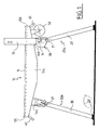
- the table shown in FIG. 1 consists essentially of a chassis 10 provided with a plate 11, two legs 20a provided to be able to take a folded position under the frame 10 and an unfolded position where they support said chassis 10.
- the plate 11 is extended on its lateral sides by two cheeks of stiffening 12a and 12b (only the cheek 12a is visible in Fig. 1) respectively for example for fixing a disc saw (not shown) by through two stiffening cheeks 12a and 12b (only the cheek 12a is visible in FIG. 1) and a tool attachment device 13.
- a handle 40 is attached to each of the longitudinal sides 12c and 12d of the chassis 10.
- a set of wheels 50 is mounted under the plate 11 near one longitudinal sides 12c or 12d.
- the frame 10 is supported by two legs 20a and 20b formed of two feet 20 secured to one another by means of a spacer 21.
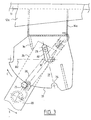
- Each foot 20 is mounted in a locking device 30 constituted, in the embodiment shown, a flange 31 fixed to each of the two ends of two sleepers 14a or 14b themselves transversely fixed under the plateau 11 between the cheeks 12a and 12b.
- the wall of the flange 31 has a light 32 which has a L shape of main axis A1 and secondary axis A2 and whose ends have a form of semicircle.
- an axis 23 which is mounted in a front wall 24 of said foot 20 can slide in said light 32.
- the axis 23 is positioned at a short distance from the upper end of the foot 20, in a median plane to the front wall 24.
- Said front wall 24 of the foot 20 is provided to contact the flange 31, preferably with its inner face as this is shown in FIG. 2.
- the flange 31 is also delimited at one of its edges by a cam 33 whose the profile has a shape of a portion of a circle.
- the cam 33 is framed, of a part, by a first groove 34 of semicylindrical section whose center is located in the extension of the main axis A1 of the light 32 and, on the other hand, by a second groove 35 of semi-cylindrical section whose center is located in the extension of the secondary axis A2 of the light 32.
- a pin 25 is also mounted in a median plane of the foot 20 so as to away from the axis 23 by a distance equal to the game close to the distance between the axis of the high end of the light, and the axis of the first groove 34 of the same flange.
- the foot 20 or the base 20a is immobilized and locked in one of its two positions: its folded position and unfolded position.
- the pin 25 can slide along the profile of said cam 33.
- a first stop 36 is attached to the wall of the flange 31 receiving the front wall 24 of the foot 20, in this case the inner wall of said flange in FIG. 2. It is disposed between the second groove 35 and the light 32 so that it can come into contact with a side wall 26 of the foot 20, when said foot 20 is in an unfolded position as shown in FIG. 2.
- Said abutment 36 also extends to the normal of the axis 23 projected on the side wall 26, that is to say not far from the upper end of the foot 20, to serve tipping point to said foot 20 during folding.
- a second stop 37 is attached to the inner wall of the flange 31. It is arranged so that it can come into contact with a side wall 27 opposite to the side wall 26 of the foot 20, when said foot is maneuvered in position unfolded as shown in FIG. 2.
- a return means 28 which is, for example, a tension spring as this is shown in FIG. 2, is installed so that each peg 25 exerts a restoring force on the foot 20 or the base 20a so as to hold the pawn 25 located either inside the groove 34 or inside the groove 25, or the along the profile of the cam 33.
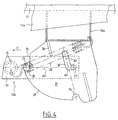
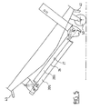
- the return means is for example mounted between a cross member 14a or 14b and the spacer 21 of a base 20a or 20b. It is further positioned so that the axis connecting its two attachment points passes either on one side of the axis 23 when the foot 20 is in the folded position, as can be seen in FIG. 4, on the other side of the axis 23 when the foot 20 is in the unfolded position as can be seen in FIG. 2.
- FIG. 2 the table of the invention is shown in working position, that is to say with his feet 20 unfolded.
- each of the legs 20 thus leaves the first groove 34 of a flange 31, which allows rotation to the base 20a around each axis 23. Then, the user rotates the base 20a so that each pin 25 can slide along the profile of the cam 33 of a flange 31 as indicates the arrow C in FIG. 3.
- the return means 28 keeps in contact the pin 25 of each of the legs 20 against the profile of the cam 33 of a flange 31.
- the side wall 26 of each of the feet 20 then comes into contact with the first stop 36 of a flange 31, which allows the shaft 23 of each of the legs 20 to slide along the main axis A1 of the light 32 of a flange 31.
- each of the legs 20 continues its movement on the profile of the cam 33 of a flange 31 so that the axis connecting the two attachment points of the return means 28 crosses each of the axes 23 and passes on the other side of said axes, this which reduces the maneuvering force required to fold the base 20a.
- the folding table can be lifted by its handles 40. It can also be moved by a handle 40, the table resting on the ground on its casters 50.
- the user exerts traction on the base 20a in the direction indicated by the arrow D of FIG. 4. It can for example exert this traction in pulling on one of the legs 20 of the base 20a, or exert a traction on the spacer 21 connecting the base 20a.
- the pin 25 of each of the legs 20 then leaves the second 35 of a flange 31, while the axis 23 of each of the feet 20 slides along of the secondary axis A2 of the light 32 of a flange 31. Then, the user leads in rotation the base 20a about the axes 23, as indicated by the arrow E of FIG. 3.
- the axis connecting the two attachment points of the return means 28 intersects a once again each axis 23 and passes on the other side of said axes, which reduces the maneuvering force necessary to unfold the base 20a.
- each of the feet 20 comes into contact with it. moment with the second stop 37 of a flange 31, which further limits the angular displacement of each of the feet 20.
- a third wall of a foot the wall front 24 is in contact with a flange 31.
- three walls 26, 27 and 24 of each of the feet 20 is in contact with a flange 31 when said foot is in its unfolded position. This results in a high rigidity of the connection of the chassis 10 of the table and his feet 20.
Landscapes
- Tables And Desks Characterized By Structural Shape (AREA)
- Ladders (AREA)
- Motorcycle And Bicycle Frame (AREA)
- Finger-Pressure Massage (AREA)
- Prostheses (AREA)
- Rehabilitation Tools (AREA)
Claims (9)
- Tisch umfassend ein Chassis (10) und wenigstens einen Fuß (20) oder ein Gestell (20a), welches um eine Achse (23) schwenkbar ist, so dass es unter dem Chassis (10) eine zusammengeklappte Position und eine ausgeklappte Position einnehmen kann, in der es das Chassis (10) trägt, wobei der Tisch außerdem eine Feststellvorrichtung (30) zum Blockieren des oder jedes Fußes (20) oder des Gestells (20a) in der einen und anderen Position mittels einer Rückstellvorrichtung (28) umfasst, dadurch gekennzeichnet, dass die Rückstellvorrichtung (28) so angeordnet ist, dass die Achse, die die beiden Befestigungspunkte der Rückstellvorrichtung (28) miteinander verbindet, die Gelenkachse (23) entweder von der einen Seite passiert hat, wenn sich der Fuß (20) oder das Gestell (20a) in zusammengeklappter Position befindet, oder die Gelenkachse (23) von der anderen Seite passiert hat, wenn sich der Fuß (20) oder das Tischgestell (20a) in der ausgeklappten Position befindet.
- Tisch nach Anspruch 1, dadurch gekennzeichnet, dass die Blockiervorrichtung (30) zwei Auskehlungen (34 und 35) zur Aufnahme eines Metallstücks (25) sowohl in der zusammengeklappten als auch in der ausgeklappten Positionen umfasst, wobei das Metallstück (25) von den Rückstellmitteln (28) in die eine oder andere Auskehlung (34 und 35) zurückgestellt wird.
- Tisch nach Anspruch 1 oder 2, dadurch gekennzeichnet, dass die Blockiervorrichtung (30) Gleitmittel umfasst, um das Gleiten jedes Fußes (20) oder Gestells (20a) zu gestatten, so dass die Blockierung und die Antiblockierung sowohl in der zusammengeklappten als auch in der ausgeklappten Positionen stattfinden kann.
- Tisch nach Anspruch 3, dadurch gekennzeichnet, dass die Gleitmittel aus einem Langloch (32) bestehen, das dazu dient, die Gelenkachse (23) in Richtung der einen und anderen Auskehlung (34, 35) gleiten zu lassen.
- Tisch nach einem der Ansprüche 2 bis 4, dadurch gekennzeichnet, dass das Metallstück (25) dazu bestimmt ist, auf dem Profil eine Kurvenscheibe (33), welche zwischen der ersten und zweiten Auskehlung (34, 35) angeordnet ist, zu gleiten, wenn der Fuß (20) oder das Gestell (20a) von seiner zusammengeklappten Position in seine ausgeklappte Position übergeht und umgekehrt.
- Tisch nach einem der vorangehenden Ansprüche, dadurch gekennzeichnet, dass die Feststellvorrichtung (30) einen ersten und zweiten Anschlag (36, 37) besitzt, welche dazu bestimmt sind, als Anschlag für die Seitenwände (26, 27) eines Fußes (20) oder Gestells (20a) zu dienen, wenn sich der Fuß oder das Gestell in seiner ausgeklappten Position befindet.
- Tisch nach Anspruch 6, dadurch gekennzeichnet, dass der erste Anschlag (36) dazu dient, die Winkelverschiebung eines Fußes (20) oder eines Gestells (20a) in seiner zusammengeklappten Position zu begrenzen.
- Tisch nach Anspruch 6 oder 7, dadurch gekennzeichnet, dass sich der erste Anschlag (36) bis zur auf die Seitenwand (26) projizierten Senkrechten der Achse (23) erstreckt, um während des Klappvorgangs als Drehpunkt eines Fußes (20) oder Gestells (20a) zu dienen.
- Tisch nach einem der vorangehenden Ansprüche, dadurch gekennzeichnet, dass er wenigstens mit einem Handgriff (40) oder einem Satz Rollen (50) versehen ist.
Applications Claiming Priority (2)
| Application Number | Priority Date | Filing Date | Title |
|---|---|---|---|
| FR9914208 | 1999-11-08 | ||
| FR9914208A FR2800587B1 (fr) | 1999-11-08 | 1999-11-08 | Table de type ayant au moins un pied ou pietinement repliable |
Publications (2)
| Publication Number | Publication Date |
|---|---|
| EP1097656A1 EP1097656A1 (de) | 2001-05-09 |
| EP1097656B1 true EP1097656B1 (de) | 2004-05-19 |
Family
ID=9552031
Family Applications (1)
| Application Number | Title | Priority Date | Filing Date |
|---|---|---|---|
| EP00460059A Expired - Lifetime EP1097656B1 (de) | 1999-11-08 | 2000-11-03 | Tischart welche mit mindestens einem faltbaren Fuss oder Untergestell versehen ist |
Country Status (6)
| Country | Link |
|---|---|
| EP (1) | EP1097656B1 (de) |
| AT (1) | ATE266954T1 (de) |
| DE (1) | DE60010832T2 (de) |
| ES (1) | ES2221834T3 (de) |
| FR (1) | FR2800587B1 (de) |
| PT (1) | PT1097656E (de) |
Families Citing this family (4)
| Publication number | Priority date | Publication date | Assignee | Title |
|---|---|---|---|---|
| GB2420696B (en) * | 2004-12-01 | 2009-08-19 | Rexon Ind Corp Ltd | Locking device for foldable stand for machine and foldable stand for machine comprising the same |
| US7341006B2 (en) * | 2005-10-31 | 2008-03-11 | Alltrade Tools Llc | Folding table assembly |
| GB2466933B (en) * | 2009-01-12 | 2010-12-08 | Bce | Tabletop |
| DE102019134452A1 (de) * | 2019-12-16 | 2021-06-17 | Hamm Ag | Zusatzgerät, insbesondere Splittstreuer |
Family Cites Families (2)
| Publication number | Priority date | Publication date | Assignee | Title |
|---|---|---|---|---|
| US3396928A (en) * | 1966-07-15 | 1968-08-13 | Hamilton Cosco Inc | Leg mounting |
| US4144822A (en) * | 1977-01-24 | 1979-03-20 | Roberts Mfg., Inc. | Folding leg mechanism |
-
1999
- 1999-11-08 FR FR9914208A patent/FR2800587B1/fr not_active Expired - Fee Related
-
2000
- 2000-11-03 EP EP00460059A patent/EP1097656B1/de not_active Expired - Lifetime
- 2000-11-03 DE DE60010832T patent/DE60010832T2/de not_active Expired - Lifetime
- 2000-11-03 AT AT00460059T patent/ATE266954T1/de not_active IP Right Cessation
- 2000-11-03 PT PT00460059T patent/PT1097656E/pt unknown
- 2000-11-03 ES ES00460059T patent/ES2221834T3/es not_active Expired - Lifetime
Also Published As
| Publication number | Publication date |
|---|---|
| EP1097656A1 (de) | 2001-05-09 |
| FR2800587A1 (fr) | 2001-05-11 |
| DE60010832D1 (de) | 2004-06-24 |
| ATE266954T1 (de) | 2004-06-15 |
| FR2800587B1 (fr) | 2002-01-11 |
| ES2221834T3 (es) | 2005-01-16 |
| DE60010832T2 (de) | 2005-07-07 |
| PT1097656E (pt) | 2004-10-29 |
Similar Documents
| Publication | Publication Date | Title |
|---|---|---|
| EP1905921B1 (de) | Perfektionierte Faltkonstruktion für Arbeiten im Freivorbau | |
| EP3415707B1 (de) | Zusammenklappbare arbeitsplattform mit geringem platzbedarf und mit sicherheitsgeländer | |
| FR2510060A1 (fr) | Poussette de bebe | |
| FR2904801A3 (fr) | Dispositif de verrouillage pour une poussette | |
| EP2666905B1 (de) | Bügelbrett mit zwei x-förmig angeordneten Stützbeinen | |
| EP1097656B1 (de) | Tischart welche mit mindestens einem faltbaren Fuss oder Untergestell versehen ist | |
| FR2666553A1 (fr) | Chariot equipe d'une partie de reception de marchandises reliee a un coulisseau mobile en hauteur, et dispositif de guidage pour ce coulisseau. | |
| EP0204637B1 (de) | Bewegliche Werkbank mit rein mechanischen Bewegungsmitteln | |
| FR2642287A1 (fr) | Durcisseur de matelas portatif | |
| FR2980229A1 (fr) | Structure en encorbellement equipee d'un mecanisme de blocage/deblocage et procede de depliage/pliage d'une telle structure | |
| FR2666620A1 (fr) | Echelle pliante. | |
| EP1693276B1 (de) | Zusammenklappbarer Kinderwagen mit einer drehbaren Fussstütze | |
| FR2777929A1 (fr) | Plate-forme telescopique | |
| EP3780997B1 (de) | Einziehbarer sitz für hockposition | |
| FR3136641A1 (fr) | Table pliable avec mécanisme intégré d’ajustement de la hauteur du plateau et de son inclinaison | |
| EP0025737B1 (de) | Transportierbare Werkzeugmaschine | |
| EP4539706A1 (de) | Klapptisch mit teleskopischen beinen | |
| FR2828522A1 (fr) | Echelle, en particulier pour caravanes autotractees et vehicules automobiles analogues | |
| WO2003015995A1 (fr) | Etabli pliant perfectionne | |
| WO2003092438A2 (fr) | Tabourets extensibles | |
| FR2729164A1 (fr) | Panneau de signalisation deployable | |
| FR3154029A1 (fr) | Table de découpe et son procédé de déploiement | |
| FR2732567A1 (fr) | Dispositif de verrouillage de meubles basculants | |
| FR3102654A1 (fr) | Table extensible à roulettes | |
| EP3354411A1 (de) | Klappwerkbank für schreinerarbeiten |
Legal Events
| Date | Code | Title | Description |
|---|---|---|---|
| PUAI | Public reference made under article 153(3) epc to a published international application that has entered the european phase |
Free format text: ORIGINAL CODE: 0009012 |
|
| AK | Designated contracting states |
Kind code of ref document: A1 Designated state(s): AT BE CH CY DE DK ES FI FR GB GR IE IT LI LU MC NL PT SE TR |
|
| AX | Request for extension of the european patent |
Free format text: AL;LT;LV;MK;RO;SI |
|
| 17P | Request for examination filed |
Effective date: 20010920 |
|
| AKX | Designation fees paid |
Free format text: AT BE CH CY DE DK ES FI FR GB GR IE IT LI LU MC NL PT SE TR |
|
| GRAP | Despatch of communication of intention to grant a patent |
Free format text: ORIGINAL CODE: EPIDOSNIGR1 |
|
| GRAS | Grant fee paid |
Free format text: ORIGINAL CODE: EPIDOSNIGR3 |
|
| GRAA | (expected) grant |
Free format text: ORIGINAL CODE: 0009210 |
|
| AK | Designated contracting states |
Kind code of ref document: B1 Designated state(s): AT BE CH CY DE DK ES FI FR GB GR IE IT LI LU MC NL PT SE TR |
|
| PG25 | Lapsed in a contracting state [announced via postgrant information from national office to epo] |
Ref country code: CY Free format text: LAPSE BECAUSE OF FAILURE TO SUBMIT A TRANSLATION OF THE DESCRIPTION OR TO PAY THE FEE WITHIN THE PRESCRIBED TIME-LIMIT Effective date: 20040519 Ref country code: AT Free format text: LAPSE BECAUSE OF FAILURE TO SUBMIT A TRANSLATION OF THE DESCRIPTION OR TO PAY THE FEE WITHIN THE PRESCRIBED TIME-LIMIT Effective date: 20040519 Ref country code: IE Free format text: LAPSE BECAUSE OF FAILURE TO SUBMIT A TRANSLATION OF THE DESCRIPTION OR TO PAY THE FEE WITHIN THE PRESCRIBED TIME-LIMIT Effective date: 20040519 Ref country code: FI Free format text: LAPSE BECAUSE OF FAILURE TO SUBMIT A TRANSLATION OF THE DESCRIPTION OR TO PAY THE FEE WITHIN THE PRESCRIBED TIME-LIMIT Effective date: 20040519 Ref country code: TR Free format text: LAPSE BECAUSE OF FAILURE TO SUBMIT A TRANSLATION OF THE DESCRIPTION OR TO PAY THE FEE WITHIN THE PRESCRIBED TIME-LIMIT Effective date: 20040519 |
|
| REG | Reference to a national code |
Ref country code: GB Ref legal event code: FG4D Free format text: NOT ENGLISH |
|
| REG | Reference to a national code |
Ref country code: CH Ref legal event code: EP |
|
| GBT | Gb: translation of ep patent filed (gb section 77(6)(a)/1977) |
Effective date: 20040519 |
|
| REG | Reference to a national code |
Ref country code: IE Ref legal event code: FG4D Free format text: FRENCH |
|
| REF | Corresponds to: |
Ref document number: 60010832 Country of ref document: DE Date of ref document: 20040624 Kind code of ref document: P |
|
| PG25 | Lapsed in a contracting state [announced via postgrant information from national office to epo] |
Ref country code: DK Free format text: LAPSE BECAUSE OF FAILURE TO SUBMIT A TRANSLATION OF THE DESCRIPTION OR TO PAY THE FEE WITHIN THE PRESCRIBED TIME-LIMIT Effective date: 20040819 Ref country code: SE Free format text: LAPSE BECAUSE OF FAILURE TO SUBMIT A TRANSLATION OF THE DESCRIPTION OR TO PAY THE FEE WITHIN THE PRESCRIBED TIME-LIMIT Effective date: 20040819 |
|
| REG | Reference to a national code |
Ref country code: GR Ref legal event code: EP Ref document number: 20040402855 Country of ref document: GR |
|
| REG | Reference to a national code |
Ref country code: PT Ref legal event code: SC4A Free format text: AVAILABILITY OF NATIONAL TRANSLATION Effective date: 20040817 |
|
| PG25 | Lapsed in a contracting state [announced via postgrant information from national office to epo] |
Ref country code: LU Free format text: LAPSE BECAUSE OF NON-PAYMENT OF DUE FEES Effective date: 20041103 |
|
| PG25 | Lapsed in a contracting state [announced via postgrant information from national office to epo] |
Ref country code: MC Free format text: LAPSE BECAUSE OF NON-PAYMENT OF DUE FEES Effective date: 20041130 Ref country code: LI Free format text: LAPSE BECAUSE OF NON-PAYMENT OF DUE FEES Effective date: 20041130 Ref country code: CH Free format text: LAPSE BECAUSE OF NON-PAYMENT OF DUE FEES Effective date: 20041130 |
|
| REG | Reference to a national code |
Ref country code: IE Ref legal event code: FD4D |
|
| REG | Reference to a national code |
Ref country code: ES Ref legal event code: FG2A Ref document number: 2221834 Country of ref document: ES Kind code of ref document: T3 |
|
| PLBE | No opposition filed within time limit |
Free format text: ORIGINAL CODE: 0009261 |
|
| STAA | Information on the status of an ep patent application or granted ep patent |
Free format text: STATUS: NO OPPOSITION FILED WITHIN TIME LIMIT |
|
| 26N | No opposition filed |
Effective date: 20050222 |
|
| REG | Reference to a national code |
Ref country code: CH Ref legal event code: PL |
|
| REG | Reference to a national code |
Ref country code: FR Ref legal event code: CA Ref country code: FR Ref legal event code: CD |
|
| PG25 | Lapsed in a contracting state [announced via postgrant information from national office to epo] |
Ref country code: IT Free format text: LAPSE BECAUSE OF NON-PAYMENT OF DUE FEES Effective date: 20091103 |
|
| PGRI | Patent reinstated in contracting state [announced from national office to epo] |
Ref country code: IT Effective date: 20110616 |
|
| PGFP | Annual fee paid to national office [announced via postgrant information from national office to epo] |
Ref country code: NL Payment date: 20130911 Year of fee payment: 14 |
|
| PGFP | Annual fee paid to national office [announced via postgrant information from national office to epo] |
Ref country code: GR Payment date: 20131202 Year of fee payment: 14 |
|
| PGFP | Annual fee paid to national office [announced via postgrant information from national office to epo] |
Ref country code: PT Payment date: 20140505 Year of fee payment: 15 |
|
| REG | Reference to a national code |
Ref country code: NL Ref legal event code: V1 Effective date: 20150601 |
|
| REG | Reference to a national code |
Ref country code: GR Ref legal event code: ML Ref document number: 20040402855 Country of ref document: GR Effective date: 20150604 |
|
| PG25 | Lapsed in a contracting state [announced via postgrant information from national office to epo] |
Ref country code: NL Free format text: LAPSE BECAUSE OF NON-PAYMENT OF DUE FEES Effective date: 20150601 Ref country code: GR Free format text: LAPSE BECAUSE OF NON-PAYMENT OF DUE FEES Effective date: 20150604 |
|
| REG | Reference to a national code |
Ref country code: FR Ref legal event code: PLFP Year of fee payment: 16 |
|
| PGFP | Annual fee paid to national office [announced via postgrant information from national office to epo] |
Ref country code: GB Payment date: 20150904 Year of fee payment: 16 |
|
| PGFP | Annual fee paid to national office [announced via postgrant information from national office to epo] |
Ref country code: BE Payment date: 20150921 Year of fee payment: 16 |
|
| PGFP | Annual fee paid to national office [announced via postgrant information from national office to epo] |
Ref country code: DE Payment date: 20150921 Year of fee payment: 16 Ref country code: IT Payment date: 20150910 Year of fee payment: 16 |
|
| PGFP | Annual fee paid to national office [announced via postgrant information from national office to epo] |
Ref country code: FR Payment date: 20151002 Year of fee payment: 16 Ref country code: ES Payment date: 20151022 Year of fee payment: 16 |
|
| REG | Reference to a national code |
Ref country code: PT Ref legal event code: MM4A Free format text: LAPSE DUE TO NON-PAYMENT OF FEES Effective date: 20160503 |
|
| PG25 | Lapsed in a contracting state [announced via postgrant information from national office to epo] |
Ref country code: PT Free format text: LAPSE BECAUSE OF NON-PAYMENT OF DUE FEES Effective date: 20160503 |
|
| PG25 | Lapsed in a contracting state [announced via postgrant information from national office to epo] |
Ref country code: BE Free format text: LAPSE BECAUSE OF NON-PAYMENT OF DUE FEES Effective date: 20161130 |
|
| REG | Reference to a national code |
Ref country code: DE Ref legal event code: R119 Ref document number: 60010832 Country of ref document: DE |
|
| GBPC | Gb: european patent ceased through non-payment of renewal fee |
Effective date: 20161103 |
|
| REG | Reference to a national code |
Ref country code: FR Ref legal event code: ST Effective date: 20170731 |
|
| PG25 | Lapsed in a contracting state [announced via postgrant information from national office to epo] |
Ref country code: FR Free format text: LAPSE BECAUSE OF NON-PAYMENT OF DUE FEES Effective date: 20161130 Ref country code: IT Free format text: LAPSE BECAUSE OF NON-PAYMENT OF DUE FEES Effective date: 20161103 |
|
| PG25 | Lapsed in a contracting state [announced via postgrant information from national office to epo] |
Ref country code: DE Free format text: LAPSE BECAUSE OF NON-PAYMENT OF DUE FEES Effective date: 20170601 Ref country code: GB Free format text: LAPSE BECAUSE OF NON-PAYMENT OF DUE FEES Effective date: 20161103 |
|
| REG | Reference to a national code |
Ref country code: BE Ref legal event code: MM Effective date: 20161130 |
|
| REG | Reference to a national code |
Ref country code: ES Ref legal event code: FD2A Effective date: 20180507 |
|
| PG25 | Lapsed in a contracting state [announced via postgrant information from national office to epo] |
Ref country code: ES Free format text: LAPSE BECAUSE OF FAILURE TO SUBMIT A TRANSLATION OF THE DESCRIPTION OR TO PAY THE FEE WITHIN THE PRESCRIBED TIME-LIMIT Effective date: 20040519 |
|
| PG25 | Lapsed in a contracting state [announced via postgrant information from national office to epo] |
Ref country code: ES Free format text: LAPSE BECAUSE OF FAILURE TO SUBMIT A TRANSLATION OF THE DESCRIPTION OR TO PAY THE FEE WITHIN THE PRESCRIBED TIME-LIMIT Effective date: 20161104 |
|
| RIC2 | Information provided on ipc code assigned after grant |
Ipc: A47B 3/08 20060101AFI20010221BHEP |