EP1095709A2 - Verfahren und Vorrichtung zum Auftrag eines Materials auf Substrate - Google Patents
Verfahren und Vorrichtung zum Auftrag eines Materials auf Substrate Download PDFInfo
- Publication number
- EP1095709A2 EP1095709A2 EP00122508A EP00122508A EP1095709A2 EP 1095709 A2 EP1095709 A2 EP 1095709A2 EP 00122508 A EP00122508 A EP 00122508A EP 00122508 A EP00122508 A EP 00122508A EP 1095709 A2 EP1095709 A2 EP 1095709A2
- Authority
- EP
- European Patent Office
- Prior art keywords
- pattern
- dispenser
- adhesive
- substrate
- dispense
- Prior art date
- Legal status (The legal status is an assumption and is not a legal conclusion. Google has not performed a legal analysis and makes no representation as to the accuracy of the status listed.)
- Granted
Links
Images


Classifications
-
- B—PERFORMING OPERATIONS; TRANSPORTING
- B05—SPRAYING OR ATOMISING IN GENERAL; APPLYING FLUENT MATERIALS TO SURFACES, IN GENERAL
- B05C—APPARATUS FOR APPLYING FLUENT MATERIALS TO SURFACES, IN GENERAL
- B05C11/00—Component parts, details or accessories not specifically provided for in groups B05C1/00 - B05C9/00
- B05C11/10—Storage, supply or control of liquid or other fluent material; Recovery of excess liquid or other fluent material
- B05C11/1044—Apparatus or installations for supplying liquid or other fluent material to several applying apparatus or several dispensing outlets, e.g. to several extrusion nozzles
-
- B—PERFORMING OPERATIONS; TRANSPORTING
- B05—SPRAYING OR ATOMISING IN GENERAL; APPLYING FLUENT MATERIALS TO SURFACES, IN GENERAL
- B05B—SPRAYING APPARATUS; ATOMISING APPARATUS; NOZZLES
- B05B12/00—Arrangements for controlling delivery; Arrangements for controlling the spray area
- B05B12/02—Arrangements for controlling delivery; Arrangements for controlling the spray area for controlling time, or sequence, of delivery
- B05B12/04—Arrangements for controlling delivery; Arrangements for controlling the spray area for controlling time, or sequence, of delivery for sequential operation or multiple outlets
-
- B—PERFORMING OPERATIONS; TRANSPORTING
- B05—SPRAYING OR ATOMISING IN GENERAL; APPLYING FLUENT MATERIALS TO SURFACES, IN GENERAL
- B05C—APPARATUS FOR APPLYING FLUENT MATERIALS TO SURFACES, IN GENERAL
- B05C11/00—Component parts, details or accessories not specifically provided for in groups B05C1/00 - B05C9/00
- B05C11/10—Storage, supply or control of liquid or other fluent material; Recovery of excess liquid or other fluent material
-
- B—PERFORMING OPERATIONS; TRANSPORTING
- B05—SPRAYING OR ATOMISING IN GENERAL; APPLYING FLUENT MATERIALS TO SURFACES, IN GENERAL
- B05C—APPARATUS FOR APPLYING FLUENT MATERIALS TO SURFACES, IN GENERAL
- B05C5/00—Apparatus in which liquid or other fluent material is projected, poured or allowed to flow on to the surface of the work
- B05C5/02—Apparatus in which liquid or other fluent material is projected, poured or allowed to flow on to the surface of the work the liquid or other fluent material being discharged through an outlet orifice by pressure, e.g. from an outlet device in contact or almost in contact, with the work
- B05C5/027—Coating heads with several outlets, e.g. aligned transversally to the moving direction of a web to be coated
- B05C5/0275—Coating heads with several outlets, e.g. aligned transversally to the moving direction of a web to be coated flow controlled, e.g. by a valve
- B05C5/0279—Coating heads with several outlets, e.g. aligned transversally to the moving direction of a web to be coated flow controlled, e.g. by a valve independently, e.g. individually, flow controlled
Definitions
- This invention relates to dispensing and dispensing systems for applying materials to substrates.
- this invention relates to the dispensing of adhesives, sealants, caulks, fluxes, encapsulants, and paints.
- This invention is especially suited to those dispensing applications which require assurance that the material has been deposited onto the substrate and which includes a means for having redundant dispensing so that production may continue in the event of a failure.
- Applicators otherwise known as dispensers, guns, or valves, particularly to apply materials to a substrate for adhesion (adhesives, fluxes, etc.) and sealing (paints, encapsulants, etc.). It is also known to provide detection systems (ultraviolet, infrared, vision, etc.) to determine if the material has properly been dispensed. If the material has not been properly dispensed, the substrate may be rejected and/or the line shut down.
- detection systems ultraviolet, infrared, vision, etc.
- failure to properly apply the material to the substrate may cause damage to the substrate and/or cause the substrate or its contents to interfere with the line thereby causing unnecessary down time.
- the failure to properly seal the case or carton may result in the cans spilling from the container onto the conveyor and/or the production floor.
- the cans may rupture, thereby spilling their contents or may jam the conveying system or otherwise interfere with the transportation of other properly sealed containers. This results in unnecessary down time in cleaning up this accident.
- An object of the present invention is to provide a method and apparatus for dispensing material onto a substrate wherein upon the failure of a dispenser, another dispenser will automatically perform the function of the failed dispenser. This has the advantage of maintaining production until the failed dispenser may be serviced at a more convenient time, such as at the end of a normal production shift. This may be accomplished, by utilizing a standby or secondary dispenser should the first gun fail.
- a dispenser to dispense a first pattern of material onto a substrate; causing another dispenser to dispense a second pattern of material onto the substrate; and upon the detection of the failure of material to be dispensed by one of the dispensers, automatically causing the other dispenser to dispense both first and second patterns of material onto the substrate.
- a method for depositing a material pattern onto a substrate comprising the steps of: dispensing material from a first dispenser so as to deposit a first portion of the pattern of material on the substrate; then dispensing material from a second dispenser to deposit a second portion of the pattern of material on the substrate; sensing the material dispensed from said first and second sensors; and upon determining the absence of the first or second portion of the pattern of material dispensed, automatically causing one of said dispensers to deposit both the first and second portions of the pattern of material to be deposited onto a subsequent substrate.
- a method for dispensing material comprising the steps of: determining a first actuation sequence; determining a second actuation sequence; determining a third actuation sequence; controlling the actuation of a first dispenser, for dispensing material, in accordance with the first actuation sequence; controlling the actuation of a second dispenser for dispensing material, in accordance with the second actuation sequence; detecting the failure of the first dispenser to dispense the material; and controlling the actuation of the second dispenser in accordance with the third actuation sequence.
- a method for dispensing adhesive onto a substrate in a pattern having a plurality of discrete adhesive deposits comprising the steps of: a) alternating the actuation of two adhesive dispensers, to dispense discrete streams or drops of adhesive onto the substrate in a pattern; b) sensing the dispensed adhesive; and c) upon the detection of a failure to dispense adhesive, causing a de-activation of the dispenser failing to dispense the adhesive and causing the other dispenser to be actuated to dispense the discrete streams or drops of adhesive from the discharge orifice in order to maintain said pattern.
- a method of dispensing adhesive onto a substrate comprising the steps of: a) dispensing the adhesive from a first dispenser onto a substrate to produce a first dispensed pattern while maintaining a second dispenser in a standby condition; b) cycling the dispensers from standby to dispense and from dispense to standby after one of the following: i) a period of time, ii) a number of gun firings, or iii) a number of substrates; and c) upon receiving a signal indicating the failure to detect the proper amount of adhesive dispensed, automatically de-activating the dispenser while causing the dispenser in standby to be actuated to dispense the adhesive onto the substrate to produce the first dispensed pattern on at least a subsequent substrate.
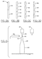
- the adhesive dispensing system 10 includes at least a pair of dispensers 12 and 14. Other pairs of dispensers may also be included, such as for example 16 and 18.
- Each dispenser may include a valve operated module 20, commonly referred to as a gun module.
- the gun module 20 may also include a nozzle 22 attached to the outlet of the gun module.
- the gun module may, for example, be a pneumatically operated valve, such as for example, a Nordson® Model H-200, Model H-400, or Model CF®-200 gun modules manufactured and sold by Nordson Corporation, Westlake, Ohio.
- the gun module 20 may alternatively be electrically driven and may be, for example, a Nordson Model E-700, E-350, or other electric gun modules manufactured and sold by Nordson Corporation.
- the gun modules may dispense the material as an extruded bead, drops, droplets, a spray, a swirl spray, etc.
- the dispensers 14 and 16 may for example, be positioned above a moving conveyor 24 which transports a substrate 26.
- the substrate may be a carton, a box, a web, a circuit board or some other object which requires a material to be dispensed onto it.
- the material to be deposited is described herein as an adhesive, other materials may be dispensed, such as for example, gasketing materials, sealants, caulks, coatings, fluxes, encapsulants, and paints.
- the material to be dispensed is a hot melt adhesive it need not be as other types of non-hot-melt-adhesive may be used instead, including a water base adhesive, commonly known as "cold glue", as well as epoxies.
- the gun modules of each dispenser may be attached to a manifold or service block 28.
- the manifold 28 includes internal passageways for supplying the adhesive to each dispenser.
- the manifold in turn is typically coupled to a source of adhesive (not shown), such as for example, an applicator unit, drum unloader, etc. for supplying the material to the manifold.
- the manifold 28 may also be coupled to a source of pressurized air (not shown) to provide air to the dispensers in pneumatically driven modules.
- the manifold will also include internal heaters, transferring heat to the hot melt adhesive, so as to maintain the liquified hot melt adhesive at its proper application temperature.
- the actuation of the dispensers 12 and 14 are commonly controlled by a controller 30, via output signals shown generally as lines 32 and 34.
- the controller 30 provides the electrical power necessary to drive the air solenoid in such a manner as to control the opening and closing of the dispenser in accordance with a desired dispensing pattern.
- the outputs 32, 34 of the controller control the actuation of the air solenoids (not shown) which in turn provide air to drive the opening and/or the closing of the piston of the pneumatic valve.
- the outputs generated by the controller therefore controls the dispensers in such a manner that the appropriate pattern of material is deposited onto the substrate.
- the desired pattern is programmed into a controller, sometimes referred to as a pattern controller, in order to obtain the desired pattern necessary for a particular application.
- a solenoid integral to the gun, drives an armature.
- the armature is the plunger or needle which mates at one end with the valve seat to thereby control the flow of the adhesive from the nozzle.
- Electric guns are typically driven by higher voltage and power requirements than those necessary to drive the typical air solenoid. Therefore, the controller for an electric gun will include not only the pattern controls, but also the circuitry to provide the necessary power to drive the armature properly. Typically, the controller for an electric gun is referred to as a gun driver.
- a detector for example a photo-detector (not shown) is positioned up stream of the dispensers 12, 14 to detect the approaching substrate 26.
- the detector provides a signal to the controller 30 which is used in conjunction with the stored pattern.
- the determination of and storage of the appropriate pattern 36 necessary to produce the desired dispensed pattern of adhesive on a substrate is well known.
- the stored pattern for a gun takes into account the speed of the substrate, the inherent on and off delays, etc. See for example, U.S. Patents 4,166,246; 4,380,967; and 4,500,937 hereby incorporated by reference herein.
- the first dispenser or gun 12 is driven via the output 34 according to a pattern 36 stored in the controller 30. Based on this pattern, the controller generates signals which in turn causes the gun to open and close to produce the desired pattern on the substrate.
- the second dispenser or gun 14 of this pair may be maintained in a standby condition. However when actuated, dispenser 14 will be driven by the controller in a manner in accordance with a second pattern 60 stored in the controller.
- a sensor 40 is mounted in such a manner as to sense the material dispensed from dispenser 12.
- the sensor 40 may be positioned for example, between the nozzle 22 and the substrate 26, thereby monitoring the material as it is being dispensed.
- a sensor 40a (indicated in phantom) may be mounted in such a manner as to monitor the dispensed material on the substrate.
- the sensor 40 generates a sensor signal 44 which corresponds to the presence or absence of the dispensed material, and is inputted to controller 30.
- the sensor signal 44 received by the controller is compared to a reference to determine if material is being dispensed properly.
- the controller When it is determined that the first dispenser has either failed to dispense adhesive or that the pattern is not complete, the controller will cause the output 32 to de-activate the first dispenser 12 while causing the second dispenser 14, to be removed from its standby condition and to be actuated according to the second pattern 60 stored in the controller 30.
- the sensor 40 may be, for example, an infrared detector, an ultrasonic detector, an optical sensor, etc. depending upon the type of adhesive being dispensed.
- the second dispenser 14 may begin its dispensing either with the next substrate 26 or, depending upon the placement of the sensing equipment, the speed of response, etc., the second dispenser 14 may begin to dispense material immediately onto the substrate, thereby placing at least some of the material onto the present substrate. While this latter method may result in the substrate not receiving a complete pattern or the proper amount of material, this may have, in certain circumstances, the benefit of allowing the substrate to be processed easier to a repair station while maintaining production. For example, in the sealing of beverage cartons, if the flap of the carton does not seal, the cans may fall from the container onto the conveyor and/or the production floor.
- the second dispenser 14 may immediately dispense adhesive onto the substrate, the amount of adhesive dispensed (while not necessarily enough to keep the container closed during normal shipment and handling), may be sufficient to keep the container closed long enough to be removed from the main conveyor line and sent to a repair station for proper gluing. This eliminates the potential opening of a container on the conveyor line thereby preventing unnecessary down time to the main processing line.
- the materials that may be dispensed may make it necessary in normal operation to cycle the second gun 14 to dispense material to prevent problems associated with a stagnate material.
- the guns may occasionally be alternated so that the first gun 12 may be placed in standby and the second gun 14 may now be the gun used for dispensing the adhesive onto the substrate.
- the rotation or cycling of the guns from a dispensing mode to a standby mode by be preprogrammed based on the passage of time, the number of substrates dispensed, gun firings, etc.
- the outlet of nozzles 22, 22a of the first and second dispensers 12, 14 will be in line substantially with one another, in the direction of movement of the substrate, so that each is able to dispense the same pattern of material.
- the guns may be mounted in any number of ways to accomplish this.
- the guns 12, 14 may be mounted to a manifold 28 wherein the manifold is in line with the direction of the movement of the substrate.
- the exact placement of the adhesive may not be that critical and as a result the first and second dispensers may be somewhat offset.
- the first and second dispensers may be configured to operate to dispense a portion of the pattern desire for each substrate.
- the first dispenser may dispense the first half of the bead 48 and the second half of the bead 50 may be dispensed by the second dispenser.
- the guns may be cycled ON/OFF through the course of a dispensing cycle to dispense various portions of the pattern.
- the first dispenser may dispense various segments of the bead 52, while the second dispenser dispenses other segments, thereby producing a completed bead.
- the pattern could include a number of spaced apart segments or beads, commonly known as a stitching pattern wherein a number of beads or segments 56 are dispensed by one dispenser and the other beads 58 are dispensed by the second dispenser, see for example Figs. 3C and 3D.
- a sensor 40a may monitor the dispensed pattern on the substrate as before or a first 40 and second 40b sensor may be used to dispense the material dispensed from the orifice of the first and second dispensers prior to its contacting the substrate.
- the other sensor Upon the sensing or the detecting of the failure of one of the first 12 or second 14 dispensers to dispense the material 42 properly, the other sensor is controlled to produce the pattern on the substrate that would have resulted from both guns.
- the first dispenser is dispensing adhesive beads 56
- the second dispenser is dispensing a second set of adhesive beads 58
- the second gun upon the detection that these patterns are not being dispensed properly, such as the absence of one or more of beads 56, such as when the first gun has failed, will be de-activated and the second gun will now be controlled to produce the complete pattern of dispensed beads 56 and 58.
- the pair of guns 12, 14 were dispensing one of the patterns of Figs. 3A - 3D for example, and one failed, the other gun would be controlled to produce the desired pattern.
- a third pattern 62 could be stored in the pattern controller such as to drive the first dispensers so that it will be able to produce the complete pattern that would normally be attained with both guns.
- a fourth pattern 63 could be stored in the pattern controller such as to drive the second dispenser so that it will be able to produce the complete pattern.
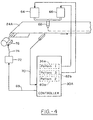
- Fig. 4 it has been known to utilize two dispensing guns 64, 66 to feed one dispensing orifice/nozzle 68.
- U.S. Patent 5,589,226, incorporated herein by reference utilizes a pair of dispensing guns in order to provide faster cycling rates to produce smaller beads and/or smaller spacing between the beads or dots.
- the first and second dispensing guns are each controlled by a controller 30a with respect to a first 36a and second pattern 60a respectively.
- the other dispensing gun Upon the detection 70 that one of the dispensing guns 64, 66 has failed to properly dispense material, such as the absence of a bead, the other dispensing gun will be controlled by another stored pattern, such as third pattern 62b or fourth 63a as above, so as to be able to continue dispensing material. However, this will necessitate a reduction in the line speed.
- a signal 69 is sent to the controller 72 controlling the line speed so that the line speed controller 72 will produce an appropriate control signal 74 to the motor drive 76 of the conveyor 24a in order to reduce the line speed. Reducing the line speed may be necessary in order to allow the gun to have sufficient time to open and close in order to properly dispense material onto the substrate in the desired pattern. This allows the production to continue, albeit, at a reduced speed, until the failure can be corrected.
- nozzles associated heretofore have been illustrated as a single orifice nozzle, they need not be.
- the nozzles could in fact be slot nozzles, or multi-orifice nozzles for producing various patterns onto the substrate.
- the nozzles of the first and second dispensers will be generally need to be substantially the same, so as to be able to each provide the required pattern should one fail.
- This invention may also be used for many other applications, including beer production.
- a dispenser 84 dispenses a shot of water 86 into the bottle of beer. This causes the beer to foam thereby producing gas which in turn evacuates the bottle of air prior to capping.
- a sensor 88 may be disposed between the orifice or nozzle 90 of the dispenser 84 and the mouth 92 of the bottle, if the sensor 88 fails to verify the shot of water dispensed from the first dispenser 84, a second dispenser 94 could be activated to dispense the shot of water as the bottle 80 passed beneath it in order to ensure that the water was actually dispensed into the beer, thereby ensuring that air has been evacuated from the bottle prior to capping.
Landscapes
- Coating Apparatus (AREA)
- Application Of Or Painting With Fluid Materials (AREA)
- Apparatuses And Processes For Manufacturing Resistors (AREA)
- Packaging Frangible Articles (AREA)
- Non-Metallic Protective Coatings For Printed Circuits (AREA)
- Manufacturing Of Printed Circuit Boards (AREA)
- Manufacturing Of Printed Wiring (AREA)
Applications Claiming Priority (2)
| Application Number | Priority Date | Filing Date | Title |
|---|---|---|---|
| US429993 | 1999-10-29 | ||
| US09/429,993 US6342264B1 (en) | 1999-10-29 | 1999-10-29 | Method and apparatus for dispensing material onto substrates |
Publications (3)
| Publication Number | Publication Date |
|---|---|
| EP1095709A2 true EP1095709A2 (de) | 2001-05-02 |
| EP1095709A3 EP1095709A3 (de) | 2003-08-06 |
| EP1095709B1 EP1095709B1 (de) | 2007-03-07 |
Family
ID=23705610
Family Applications (1)
| Application Number | Title | Priority Date | Filing Date |
|---|---|---|---|
| EP00122508A Expired - Lifetime EP1095709B1 (de) | 1999-10-29 | 2000-10-14 | Verfahren und Vorrichtung zum Auftrag eines Materials auf Substrate |
Country Status (8)
| Country | Link |
|---|---|
| US (1) | US6342264B1 (de) |
| EP (1) | EP1095709B1 (de) |
| JP (1) | JP4711369B2 (de) |
| AT (1) | ATE355909T1 (de) |
| AU (1) | AU765737B2 (de) |
| CA (1) | CA2322718A1 (de) |
| DE (1) | DE60033761T2 (de) |
| ES (1) | ES2280167T3 (de) |
Cited By (4)
| Publication number | Priority date | Publication date | Assignee | Title |
|---|---|---|---|---|
| WO2006121653A1 (en) * | 2005-05-06 | 2006-11-16 | Illinois Tool Works Inc. | Redundant control circuit for hot melt adhesive hose assembly heater circuits and temperature sensors |
| WO2006121727A2 (en) * | 2005-05-06 | 2006-11-16 | Illinois Tool Work Inc. | Hot melt adhesive hose assembly having redundant components |
| WO2008020929A2 (en) * | 2006-08-14 | 2008-02-21 | Illinois Tool Works Inc. | Redundant hot melt adhesive material heater elements and temperature sensors disposed within single cartridge bodies |
| WO2010145748A1 (de) * | 2009-06-18 | 2010-12-23 | Focke & Co. (Gmbh & Co. Kg) | Verfahren zum betreiben eines beleimungssystems |
Families Citing this family (26)
| Publication number | Priority date | Publication date | Assignee | Title |
|---|---|---|---|---|
| US6696944B2 (en) * | 2001-06-04 | 2004-02-24 | Ford Global Technologies, Llc | Indicating system for a manually controlled applicator |
| US6808741B1 (en) * | 2001-10-26 | 2004-10-26 | Seagate Technology Llc | In-line, pass-by method for vapor lubrication |
| US7617951B2 (en) * | 2002-01-28 | 2009-11-17 | Nordson Corporation | Compact heated air manifolds for adhesive application |
| DE50309892D1 (de) * | 2002-09-13 | 2008-07-03 | Windmoeller & Hoelscher | Vorrichtung zur bildung eines leimprofils für kreuzbodensäcke |
| BR0311895B1 (pt) * | 2002-09-13 | 2011-02-22 | dispositivo assentador de fundo para sacos de papel. | |
| US6737102B1 (en) | 2002-10-31 | 2004-05-18 | Nordson Corporation | Apparatus and methods for applying viscous material in a pattern onto one or more moving strands |
| US8058077B2 (en) * | 2003-06-20 | 2011-11-15 | Roche Diagnostics Operations, Inc. | Method for coding information on a biosensor test strip |
| US7084377B2 (en) * | 2003-10-31 | 2006-08-01 | Nordson Corporation | Heated device and method of redundant temperature sensing |
| US7117912B2 (en) * | 2003-10-31 | 2006-10-10 | Nordson Corporation | System and method for monitoring heat seal devices |
| US20050242108A1 (en) * | 2004-04-30 | 2005-11-03 | Nordson Corporation | Liquid dispenser having individualized process air control |
| US7732735B2 (en) * | 2005-05-06 | 2010-06-08 | Illinois Tool Works Inc. | Hot melt adhesive hose assembly having redundant components |
| US7351937B2 (en) * | 2005-05-06 | 2008-04-01 | Illinois Tool Works Inc. | Control circuits for hot melt adhesive heater circuits and applicator heads |
| US7605351B2 (en) * | 2005-05-06 | 2009-10-20 | Illinois Tool Works Inc. | Redundant control circuit for hot melt adhesive hose assembly heater circuits and temperature sensors |
| CH697827B1 (de) * | 2005-07-25 | 2009-02-27 | Oerlikon Assembly Equipment Ag | Einrichtung zum Auftragen von Klebstoff auf ein Substrat. |
| EP1973669B1 (de) * | 2006-01-06 | 2011-04-20 | Nordson Corporation | Flüssigkeitsspender mit individualisierter prozessluftsteuerung |
| US7732736B2 (en) * | 2007-03-30 | 2010-06-08 | Illinois Tool Works Inc. | Hot melt adhesive hose assembly with thermal fuse link |
| US20080271416A1 (en) * | 2007-05-03 | 2008-11-06 | Weyerhaeuser Co. | Sealer applicator for a fiberboard assembler |
| DE102008027259A1 (de) | 2008-06-06 | 2009-12-17 | Focke & Co.(Gmbh & Co. Kg) | Verfahren und Vorrichtung zur Herstellung von Zigarettenpackungen |
| DE102008029929A1 (de) * | 2008-06-26 | 2009-12-31 | Focke & Co.(Gmbh & Co. Kg) | Verfahren und Vorrichtung zum Herstellen von Packungen |
| DE102008053032B4 (de) * | 2008-10-24 | 2019-05-02 | Windmöller & Hölscher Kg | Vorrichtung zur Herstellung von Säcken unterschiedlichen Formats sowie Beleimungsstation |
| US9059517B2 (en) | 2012-09-04 | 2015-06-16 | The Boeing Company | Systems and methods for assembling conformal arrays |
| US9120115B2 (en) * | 2012-10-25 | 2015-09-01 | Nordson Corporation | Dispensing systems and methods for monitoring actuation signals for diagnostics |
| DE102016007417A1 (de) * | 2016-06-20 | 2017-12-21 | Focke & Co. (Gmbh & Co. Kg) | Station zum Aufbringen von fluiden Medien auf ein Substrat und Verfahren zum Betreiben derselben |
| CN108772245B (zh) * | 2018-07-09 | 2024-05-07 | 广东华粘新材料研究有限公司 | 一种直条型狭缝挤出模具与多辊组合的涂布系统 |
| WO2021044722A1 (ja) * | 2019-09-04 | 2021-03-11 | Nok株式会社 | ガスケットの製造方法 |
| IT202100023510A1 (it) * | 2021-09-13 | 2023-03-13 | Tiber Pack S P A | Metodo per proiettare colla liquida su lembi da incollare di scatole in formazione di un medesimo formato e relativa macchina |
Citations (4)
| Publication number | Priority date | Publication date | Assignee | Title |
|---|---|---|---|---|
| US4166246A (en) | 1978-01-23 | 1979-08-28 | Nordson Corporation | Digital control system for automatically compensating for conveyer movement changes |
| US4380967A (en) | 1981-09-14 | 1983-04-26 | Nordson Corporation | System for automatically coating objects with a plurality of quantities of a coating material using a single discharge apparatus |
| US4500937A (en) | 1982-11-12 | 1985-02-19 | Nordson Corporation | Control circuit for a solenoid driver for a dispenser |
| US5589226A (en) | 1992-06-04 | 1996-12-31 | Nordson Corporation | Method and device for applying liquid material, in particular a hot melt, by means of a sequentially operating applicator to a substrate |
Family Cites Families (17)
| Publication number | Priority date | Publication date | Assignee | Title |
|---|---|---|---|---|
| US4735169A (en) | 1986-09-03 | 1988-04-05 | Nordson Corporation | Adhesive applicator assembly |
| DE3763382D1 (de) | 1987-01-20 | 1990-08-02 | Nordson Corp | Geschlossene schachtel und verfahren und vorrichtung zum abgeben von leim zu deren herstellung. |
| US4984109A (en) | 1988-06-15 | 1991-01-08 | Hitachi, Ltd. | Reel support positioning device for a cassette tape recording and/or reproducing apparatus accommodating cassettes of different sizes |
| US4894252A (en) * | 1988-11-30 | 1990-01-16 | Ransburg Corporation | Coating material orifice clogging indication method and apparatus |
| JPH02172557A (ja) * | 1988-12-26 | 1990-07-04 | Konica Corp | 磁性塗布液の塗布装置 |
| US5208064A (en) | 1991-11-04 | 1993-05-04 | Nordson Corporation | Method and apparatus for optically monitoring and controlling a moving fiber of material |
| DE69317985T2 (de) | 1992-11-20 | 1998-11-12 | Nordson Corp | Methode zum Überwachen und/oder abgeben von Material auf ein Substrat |
| JPH0778233A (ja) | 1993-09-07 | 1995-03-20 | Nordson Kk | 検知方法 |
| JPH0831677B2 (ja) * | 1993-12-21 | 1996-03-27 | 株式会社精工舎 | ポッティング装置 |
| JP2745207B2 (ja) * | 1995-02-14 | 1998-04-28 | 東レエンジニアリング株式会社 | 樹脂封止装置 |
| US5666325A (en) | 1995-07-31 | 1997-09-09 | Nordson Corporation | Method and apparatus for monitoring and controlling the dispensing of materials onto a substrate |
| JP3484886B2 (ja) * | 1996-07-04 | 2004-01-06 | ソニー株式会社 | 塗布装置 |
| JP3757477B2 (ja) * | 1996-08-06 | 2006-03-22 | ソニー株式会社 | 間欠塗布装置 |
| JP2948543B2 (ja) | 1996-11-26 | 1999-09-13 | 三菱重工業株式会社 | グルーガン式糊付装置 |
| JP4022785B2 (ja) * | 1997-03-03 | 2007-12-19 | ノードソン株式会社 | 塗布パターンの位置ずれを検知する方法及びその補正方法 |
| US5922132A (en) | 1997-06-02 | 1999-07-13 | K-G Devices Corporation | Automated adhesive spray timing control |
| US5979704A (en) * | 1997-09-03 | 1999-11-09 | Loctite Corporation | Blockage compensating dispense system |
-
1999
- 1999-10-29 US US09/429,993 patent/US6342264B1/en not_active Expired - Fee Related
-
2000
- 2000-10-10 CA CA002322718A patent/CA2322718A1/en not_active Abandoned
- 2000-10-14 ES ES00122508T patent/ES2280167T3/es not_active Expired - Lifetime
- 2000-10-14 AT AT00122508T patent/ATE355909T1/de not_active IP Right Cessation
- 2000-10-14 DE DE60033761T patent/DE60033761T2/de not_active Expired - Lifetime
- 2000-10-14 EP EP00122508A patent/EP1095709B1/de not_active Expired - Lifetime
- 2000-10-20 AU AU66655/00A patent/AU765737B2/en not_active Ceased
- 2000-10-27 JP JP2000329119A patent/JP4711369B2/ja not_active Expired - Fee Related
Patent Citations (4)
| Publication number | Priority date | Publication date | Assignee | Title |
|---|---|---|---|---|
| US4166246A (en) | 1978-01-23 | 1979-08-28 | Nordson Corporation | Digital control system for automatically compensating for conveyer movement changes |
| US4380967A (en) | 1981-09-14 | 1983-04-26 | Nordson Corporation | System for automatically coating objects with a plurality of quantities of a coating material using a single discharge apparatus |
| US4500937A (en) | 1982-11-12 | 1985-02-19 | Nordson Corporation | Control circuit for a solenoid driver for a dispenser |
| US5589226A (en) | 1992-06-04 | 1996-12-31 | Nordson Corporation | Method and device for applying liquid material, in particular a hot melt, by means of a sequentially operating applicator to a substrate |
Cited By (7)
| Publication number | Priority date | Publication date | Assignee | Title |
|---|---|---|---|---|
| WO2006121653A1 (en) * | 2005-05-06 | 2006-11-16 | Illinois Tool Works Inc. | Redundant control circuit for hot melt adhesive hose assembly heater circuits and temperature sensors |
| WO2006121727A2 (en) * | 2005-05-06 | 2006-11-16 | Illinois Tool Work Inc. | Hot melt adhesive hose assembly having redundant components |
| WO2006121727A3 (en) * | 2005-05-06 | 2007-01-04 | Illinois Tool Works | Hot melt adhesive hose assembly having redundant components |
| WO2008020929A2 (en) * | 2006-08-14 | 2008-02-21 | Illinois Tool Works Inc. | Redundant hot melt adhesive material heater elements and temperature sensors disposed within single cartridge bodies |
| WO2008020929A3 (en) * | 2006-08-14 | 2008-07-03 | Illinois Tool Works | Redundant hot melt adhesive material heater elements and temperature sensors disposed within single cartridge bodies |
| WO2010145748A1 (de) * | 2009-06-18 | 2010-12-23 | Focke & Co. (Gmbh & Co. Kg) | Verfahren zum betreiben eines beleimungssystems |
| US8948898B2 (en) | 2009-06-18 | 2015-02-03 | Focke & Co. (Gmbh & Co. Kg) | Method for operating a gluing system |
Also Published As
| Publication number | Publication date |
|---|---|
| ATE355909T1 (de) | 2007-03-15 |
| JP4711369B2 (ja) | 2011-06-29 |
| ES2280167T3 (es) | 2007-09-16 |
| US6342264B1 (en) | 2002-01-29 |
| EP1095709A3 (de) | 2003-08-06 |
| AU6665500A (en) | 2001-05-03 |
| EP1095709B1 (de) | 2007-03-07 |
| AU765737B2 (en) | 2003-09-25 |
| DE60033761D1 (de) | 2007-04-19 |
| JP2001170540A (ja) | 2001-06-26 |
| DE60033761T2 (de) | 2007-11-29 |
| CA2322718A1 (en) | 2001-04-29 |
Similar Documents
| Publication | Publication Date | Title |
|---|---|---|
| EP1095709B1 (de) | Verfahren und Vorrichtung zum Auftrag eines Materials auf Substrate | |
| US8334023B2 (en) | Methods for regulating the placement of fluid dispensed from an applicator onto a workpiece | |
| US7771556B2 (en) | Apparatus and process to apply adhesive during labeling operations | |
| US6540104B1 (en) | Integral pneumatic dispenser and method for controlling same | |
| US5447254A (en) | Fluid dispenser with shut-off drip protection | |
| CN100478967C (zh) | 调节从敷涂器施放到工件上的流体的布置的方法 | |
| EP3408035B1 (de) | Klebstoffverabreichungssystem | |
| US10213806B2 (en) | Melter for supplying liquid adhesive | |
| US5540774A (en) | Drip proof dispensing method and nozzle assembly for dispensing viscous materials | |
| JPH10244211A (ja) | 塗布パターンの位置ずれを検知する方法及びその補正方法 | |
| CN110382121B (zh) | 用于无中断地涂覆罐体的装置和运行方法 | |
| KR20180062556A (ko) | 토출 헤드의 변위 모니터링이 가능한 도포장치 및 그의 제어방법 | |
| JPH11589A (ja) | 塗料給送制御システム | |
| JPH0466153A (ja) | 塗料温度調節システム | |
| JP3797227B2 (ja) | 容器への液化窒素充填方法及び装置 | |
| JP2021079348A (ja) | 搬送装置および梱包装置 | |
| GB2319486A (en) | Dispensing material | |
| JP2002257296A (ja) | 容器への液化窒素充填方法及び装置 |
Legal Events
| Date | Code | Title | Description |
|---|---|---|---|
| PUAI | Public reference made under article 153(3) epc to a published international application that has entered the european phase |
Free format text: ORIGINAL CODE: 0009012 |
|
| AK | Designated contracting states |
Kind code of ref document: A2 Designated state(s): AT BE CH CY DE DK ES FI FR GB GR IE IT LI LU MC NL PT SE |
|
| AX | Request for extension of the european patent |
Free format text: AL;LT;LV;MK;RO;SI |
|
| PUAL | Search report despatched |
Free format text: ORIGINAL CODE: 0009013 |
|
| AK | Designated contracting states |
Designated state(s): AT BE CH CY DE DK ES FI FR GB GR IE IT LI LU MC NL PT SE |
|
| AX | Request for extension of the european patent |
Extension state: AL LT LV MK RO SI |
|
| RIC1 | Information provided on ipc code assigned before grant |
Ipc: 7B 05C 5/02 B Ipc: 7B 05C 11/10 A Ipc: 7B 65B 51/02 B Ipc: 7B 05B 12/04 B Ipc: 7B 05B 12/08 B |
|
| 17P | Request for examination filed |
Effective date: 20040206 |
|
| 17Q | First examination report despatched |
Effective date: 20040309 |
|
| AKX | Designation fees paid |
Designated state(s): AT BE CH CY DE DK ES FI FR GB GR IE IT LI LU MC NL PT SE |
|
| GRAP | Despatch of communication of intention to grant a patent |
Free format text: ORIGINAL CODE: EPIDOSNIGR1 |
|
| GRAS | Grant fee paid |
Free format text: ORIGINAL CODE: EPIDOSNIGR3 |
|
| GRAA | (expected) grant |
Free format text: ORIGINAL CODE: 0009210 |
|
| AK | Designated contracting states |
Kind code of ref document: B1 Designated state(s): AT BE CH CY DE DK ES FI FR GB GR IE IT LI LU MC NL PT SE |
|
| PG25 | Lapsed in a contracting state [announced via postgrant information from national office to epo] |
Ref country code: BE Free format text: LAPSE BECAUSE OF FAILURE TO SUBMIT A TRANSLATION OF THE DESCRIPTION OR TO PAY THE FEE WITHIN THE PRESCRIBED TIME-LIMIT Effective date: 20070307 Ref country code: AT Free format text: LAPSE BECAUSE OF FAILURE TO SUBMIT A TRANSLATION OF THE DESCRIPTION OR TO PAY THE FEE WITHIN THE PRESCRIBED TIME-LIMIT Effective date: 20070307 Ref country code: FI Free format text: LAPSE BECAUSE OF FAILURE TO SUBMIT A TRANSLATION OF THE DESCRIPTION OR TO PAY THE FEE WITHIN THE PRESCRIBED TIME-LIMIT Effective date: 20070307 |
|
| REG | Reference to a national code |
Ref country code: GB Ref legal event code: FG4D |
|
| REG | Reference to a national code |
Ref country code: CH Ref legal event code: EP |
|
| REF | Corresponds to: |
Ref document number: 60033761 Country of ref document: DE Date of ref document: 20070419 Kind code of ref document: P |
|
| REG | Reference to a national code |
Ref country code: IE Ref legal event code: FG4D |
|
| PG25 | Lapsed in a contracting state [announced via postgrant information from national office to epo] |
Ref country code: SE Free format text: LAPSE BECAUSE OF FAILURE TO SUBMIT A TRANSLATION OF THE DESCRIPTION OR TO PAY THE FEE WITHIN THE PRESCRIBED TIME-LIMIT Effective date: 20070607 |
|
| REG | Reference to a national code |
Ref country code: CH Ref legal event code: NV Representative=s name: ZIMMERLI, WAGNER & PARTNER AG |
|
| PG25 | Lapsed in a contracting state [announced via postgrant information from national office to epo] |
Ref country code: PT Free format text: LAPSE BECAUSE OF FAILURE TO SUBMIT A TRANSLATION OF THE DESCRIPTION OR TO PAY THE FEE WITHIN THE PRESCRIBED TIME-LIMIT Effective date: 20070807 |
|
| REG | Reference to a national code |
Ref country code: ES Ref legal event code: FG2A Ref document number: 2280167 Country of ref document: ES Kind code of ref document: T3 |
|
| PLBE | No opposition filed within time limit |
Free format text: ORIGINAL CODE: 0009261 |
|
| STAA | Information on the status of an ep patent application or granted ep patent |
Free format text: STATUS: NO OPPOSITION FILED WITHIN TIME LIMIT |
|
| PG25 | Lapsed in a contracting state [announced via postgrant information from national office to epo] |
Ref country code: DK Free format text: LAPSE BECAUSE OF FAILURE TO SUBMIT A TRANSLATION OF THE DESCRIPTION OR TO PAY THE FEE WITHIN THE PRESCRIBED TIME-LIMIT Effective date: 20070307 |
|
| 26N | No opposition filed |
Effective date: 20071210 |
|
| PG25 | Lapsed in a contracting state [announced via postgrant information from national office to epo] |
Ref country code: GR Free format text: LAPSE BECAUSE OF FAILURE TO SUBMIT A TRANSLATION OF THE DESCRIPTION OR TO PAY THE FEE WITHIN THE PRESCRIBED TIME-LIMIT Effective date: 20070608 |
|
| PG25 | Lapsed in a contracting state [announced via postgrant information from national office to epo] |
Ref country code: MC Free format text: LAPSE BECAUSE OF NON-PAYMENT OF DUE FEES Effective date: 20071031 |
|
| PG25 | Lapsed in a contracting state [announced via postgrant information from national office to epo] |
Ref country code: IE Free format text: LAPSE BECAUSE OF NON-PAYMENT OF DUE FEES Effective date: 20071015 |
|
| PGFP | Annual fee paid to national office [announced via postgrant information from national office to epo] |
Ref country code: NL Payment date: 20081015 Year of fee payment: 9 |
|
| PGFP | Annual fee paid to national office [announced via postgrant information from national office to epo] |
Ref country code: CH Payment date: 20081015 Year of fee payment: 9 |
|
| PGFP | Annual fee paid to national office [announced via postgrant information from national office to epo] |
Ref country code: GB Payment date: 20081021 Year of fee payment: 9 |
|
| PG25 | Lapsed in a contracting state [announced via postgrant information from national office to epo] |
Ref country code: CY Free format text: LAPSE BECAUSE OF FAILURE TO SUBMIT A TRANSLATION OF THE DESCRIPTION OR TO PAY THE FEE WITHIN THE PRESCRIBED TIME-LIMIT Effective date: 20070307 |
|
| PG25 | Lapsed in a contracting state [announced via postgrant information from national office to epo] |
Ref country code: LU Free format text: LAPSE BECAUSE OF NON-PAYMENT OF DUE FEES Effective date: 20071014 |
|
| REG | Reference to a national code |
Ref country code: CH Ref legal event code: PFA Owner name: NORDSON CORPORATION Free format text: NORDSON CORPORATION#28601 CLEMENS ROAD#WESTLAKE, OHIO 44145-1119 (US) -TRANSFER TO- NORDSON CORPORATION#28601 CLEMENS ROAD#WESTLAKE, OHIO 44145-1119 (US) |
|
| REG | Reference to a national code |
Ref country code: NL Ref legal event code: V1 Effective date: 20100501 |
|
| REG | Reference to a national code |
Ref country code: CH Ref legal event code: PL |
|
| PG25 | Lapsed in a contracting state [announced via postgrant information from national office to epo] |
Ref country code: NL Free format text: LAPSE BECAUSE OF NON-PAYMENT OF DUE FEES Effective date: 20100501 |
|
| PG25 | Lapsed in a contracting state [announced via postgrant information from national office to epo] |
Ref country code: CH Free format text: LAPSE BECAUSE OF NON-PAYMENT OF DUE FEES Effective date: 20091031 Ref country code: LI Free format text: LAPSE BECAUSE OF NON-PAYMENT OF DUE FEES Effective date: 20091031 |
|
| PG25 | Lapsed in a contracting state [announced via postgrant information from national office to epo] |
Ref country code: GB Free format text: LAPSE BECAUSE OF NON-PAYMENT OF DUE FEES Effective date: 20091014 |
|
| PGFP | Annual fee paid to national office [announced via postgrant information from national office to epo] |
Ref country code: DE Payment date: 20101022 Year of fee payment: 11 |
|
| PGFP | Annual fee paid to national office [announced via postgrant information from national office to epo] |
Ref country code: IT Payment date: 20101025 Year of fee payment: 11 |
|
| PGFP | Annual fee paid to national office [announced via postgrant information from national office to epo] |
Ref country code: FR Payment date: 20111103 Year of fee payment: 12 Ref country code: ES Payment date: 20111026 Year of fee payment: 12 |
|
| REG | Reference to a national code |
Ref country code: FR Ref legal event code: ST Effective date: 20130628 |
|
| PG25 | Lapsed in a contracting state [announced via postgrant information from national office to epo] |
Ref country code: DE Free format text: LAPSE BECAUSE OF NON-PAYMENT OF DUE FEES Effective date: 20130501 |
|
| REG | Reference to a national code |
Ref country code: DE Ref legal event code: R119 Ref document number: 60033761 Country of ref document: DE Effective date: 20130501 |
|
| PG25 | Lapsed in a contracting state [announced via postgrant information from national office to epo] |
Ref country code: IT Free format text: LAPSE BECAUSE OF NON-PAYMENT OF DUE FEES Effective date: 20121014 Ref country code: FR Free format text: LAPSE BECAUSE OF NON-PAYMENT OF DUE FEES Effective date: 20121031 |
|
| REG | Reference to a national code |
Ref country code: ES Ref legal event code: FD2A Effective date: 20140509 |
|
| PG25 | Lapsed in a contracting state [announced via postgrant information from national office to epo] |
Ref country code: ES Free format text: LAPSE BECAUSE OF NON-PAYMENT OF DUE FEES Effective date: 20121015 |