EP1095707A2 - Colour change valve assembly and method for flushing a colour changer - Google Patents
Colour change valve assembly and method for flushing a colour changer Download PDFInfo
- Publication number
- EP1095707A2 EP1095707A2 EP00123535A EP00123535A EP1095707A2 EP 1095707 A2 EP1095707 A2 EP 1095707A2 EP 00123535 A EP00123535 A EP 00123535A EP 00123535 A EP00123535 A EP 00123535A EP 1095707 A2 EP1095707 A2 EP 1095707A2
- Authority
- EP
- European Patent Office
- Prior art keywords
- color
- valve
- channel
- detergent
- air
- Prior art date
- Legal status (The legal status is an assumption and is not a legal conclusion. Google has not performed a legal analysis and makes no representation as to the accuracy of the status listed.)
- Granted
Links
Images


Classifications
-
- B—PERFORMING OPERATIONS; TRANSPORTING
- B05—SPRAYING OR ATOMISING IN GENERAL; APPLYING FLUENT MATERIALS TO SURFACES, IN GENERAL
- B05B—SPRAYING APPARATUS; ATOMISING APPARATUS; NOZZLES
- B05B12/00—Arrangements for controlling delivery; Arrangements for controlling the spray area
- B05B12/14—Arrangements for controlling delivery; Arrangements for controlling the spray area for supplying a selected one of a plurality of liquids or other fluent materials or several in selected proportions to a spray apparatus, e.g. to a single spray outlet
- B05B12/149—Arrangements for controlling delivery; Arrangements for controlling the spray area for supplying a selected one of a plurality of liquids or other fluent materials or several in selected proportions to a spray apparatus, e.g. to a single spray outlet characterised by colour change manifolds or valves therefor
Definitions
- the invention relates to a color change valve arrangement with a Valve block according to the preamble of claim 1 and a method for flushing such a valve arrangement.
- Color change valve blocks or in short color changers allow in Painting systems for the serial coating of workpieces such as Motor vehicles during the painting operation quick change from one color to another and pass mainly from a number of controllable color valves that are distributed along a color channel common to all colors.
- a color pressure regulator can be arranged at the output of the color channel be, via which the color material, for example via a metering pump got to an atomizer.
- Cleaning is usually done first opened a compressed air valve, which is located on the opposite end of the color channel, and through the compressed air the residual paint into a return duct and printed from there into a collection container.
- the rinsing time can be done using a special dual-circuit technology reduce, in which in a circle of color changers and in other circle the path to the atomizer can be flushed, but increase the installation and control effort and the size of the color changer due to the required additional valves, and the amount of detergent remains relatively high.
- a color change valve arrangement is known from DE 32 21 326 A1, at both the beginning of all colors common Color channel of the color change valve block as well as on one of these Valve block via a color pressure control valve downstream of the color distribution valve block Flush valves are arranged, which are optional Introduce compressed air, solvent or a mixture of both can. Furthermore, there is a modified version of this publication Embodiment known, in which the flushing media in the direction of color flow in the opposite direction through the color changer.
- the invention has for its object a color change valve assembly and to provide a method of flushing them a reduction in rinsing time without significant additional effort and if possible also enable the consumption of detergent.
- the invention has the particular advantage that compared to comparable known color changers for a significant reduction the rinsing time and also the amount of detergent required no additional valves are required.
- a preferred use of the described here Color changers are color painting systems in which between the Color output of the color changer and a spray device such as for example one of the usual rotary or air atomizers or the like.
- a spray device such as for example one of the usual rotary or air atomizers or the like.
- a flushable metering pump or other metering device is arranged, the coating material over a Color pressure regulator is supplied, the color pressure regulator also itself can form the dosing device.
- the invention is based on an embodiment shown in the drawing explained in more detail.
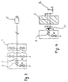
- the color changer shown schematically in Fig. 1 can known structure as a valve block 1 with any string Modules to form a housing with a straight central color channel 2 and in each case in rows along the color channel valve bodies distributed on opposite sides if necessary to have.
- the valve body contains 2 connected to the paint channel for example pneumatically controllable valves, of which a flushing agent valve V1 for the controlled introduction of at V as Detergent supplied thinner in the color changer, a pulse air valve PL1 for the controlled introduction of compressed air, various Color valves F1, F2, F3 and Fn for introducing coating material F of the selected color and a bleed valve RF2 are highlighted.
- the remaining valve positions are of no importance for the explanation of the invention.
- Color pressure regulator FDR arranged, of which a line 4 via a Dosing device, e.g. B. a metering pump 5 to an atomizer or other application organ Z leads with the usual Return valve RF1 is equipped.
- the FDR color pressure regulator limits the outlet pressure to the pump.
- the metering pump 5, for example a gear pump, is via a flushing valve V3 flushable with thinner V and provided with a bypass valve BY.
- the pulse air valve is located according to FIG. 1 PL1 now at the output end of color channel 2, so that all Color valves F1 to Fn along the color channel 2 between the pulse air valve PL1 and the one at the opposite end of the color channel located detergent and vent valves V1 and RF2 are.
- the flushing agent valve V1 is opened, so that thinner liquid from the input end of the paint channel to its exit and through it to a (not shown) Diverter valve before or on the application member Z flows.
- the subsequent changing intervals of pulse air and thinner can for example be the same Time like the pulse air valve PL1 also the vent valve RF2 opened and thus fully exploited the dynamics of the pulse air become.
- the vent valve RF2 can then again before the Pulse air valve PL1 should be closed as it is advisable if the entire pulse air is briefly through the output 3 of the Color changer is forced.
- the color pressure regulator FDR can, however, also with the vent valve RF2 open one of the pressure conditions, i.e. the flow resistance of the Color pressure regulator FDR and the subsequent line system dependent part of the pulse air or the air-detergent mixture flow towards the application organ Z.
- the entire air / detergent mixture flows when valve RF2 is closed to this exit, and when opening the vent valve RF2 reverses all or part of its flow direction around, which results in an additional cleaning effect. Since the flow resistance towards the valve RF2 is essential is lower than through the color pressure regulator FDR in the direction to the application organ, the valve is open when the RF2 valve is open to the input end of the valve block 1 flowing volume flow accordingly larger than the negligible residual flow through output 3. But it is also possible to use the color pressure regulator Close FDR when opening valve RF2.
- the rinsing process required at short notice the direction of flow of a flushing medium can be reversed in whole or in part.
- the reversal does not require the closing of a shut-off device or in the considered example of output 3, but can by opening an additional outlet, here that of the vent valve RF2 and the changing pressure conditions can be achieved.
- the reversal of the flow direction leaves in principle also with the embodiment described here different arrangements of air and thinner valves to reach.
- the flushing time is considerable due to the invention reduced (from 9.2 s to 5.8 s).
- the required Reduced amount of detergent in the example examined from 283 g to 168 g, of which 265 g in the first case and in the second Fall 140 g on the return through the return valve RF1 on Application organ Z omitted).
- rinse programs are also conceivable in which the detergent at certain times during the cleaning process the bleeder valve of the color changer is led out.
- Fig. 2 The comparison shown in Fig. 2 was made without using the usual so-called EDPS flushing system, in which the flushing medium at a higher pressure than with standard flushing an injector is directed into the color changer and in interaction with the pulsed air an aerosol is created, with which especially is rinsed intensively and in a way that saves dishwashing medium
- EDPS flush but can also be useful in the case described here Color changers can be applied.
- the A certain amount of detergent per unit of time flow through the size of the opening and the pressure of the feed Detergent can be set. Through the exit of the detergent through the nozzle opening is also atomized of the detergent is reached, which reduces the cleaning effect is improved.
- the solvent can through the upstream, as a shut-off valve serving valve V1 are clocked or flow continuously.
- the color channel 2 can be selected from those explained in EP 0 979 964 A2 For the reasons described there, from the previously usual circular shape deviating elongated, e.g. B. approximately oval cross-section have, as shown in Fig. 4 at Q. In a further embodiment it is advantageous if the jet shape comes out of the nozzle D escaping detergent of the oval cross-sectional shape of the paint channel is adjusted. So it is a conical one Flat jet ST with a color channel cross-section Opening angle ⁇ and the length a and width b of the channel cross section Q corresponding dimensions.
- the arrangement and / or shape of the nozzle D described can also in the case of arrangements of the solvent and Pulse air valves can be advantageous, even with conventional color changers with the arrangement of these two valves at the same end of the Color channel.
Abstract
Description
Die Erfindung betrifft eine Farbwechselventilanordnung mit einem Ventilblock gemäß dem Oberbegriff des Anspruchs 1 sowie ein Verfahren zum Spülen einer solchen Ventilanordnung.The invention relates to a color change valve arrangement with a Valve block according to the preamble of claim 1 and a method for flushing such a valve arrangement.
Farbwechselventilblöcke oder kurz Farbwechsler ermöglichen in Lackieranlagen zur Serienbeschichtung von Werkstücken wie beispielsweise Kraftfahrzeugen während des Lackierbetriebes eine rasche Umstellung von einer Farbe zur anderen und bestehen hauptsächlich aus einer Anzahl von steuerbaren Farbventilen, die längs eines allen Farben gemeinsamen Farbkanals verteilt sind. Am Ausgang des Farbkanals kann ein Farbdruckregler angeordnet sein, über den das Farbmaterial beispielsweise über eine Dosierpumpe zu einem Zerstäuber gelangt. Vor der Umstellung auf eine neue Farbe ist es jeweils notwendig, alle farbführenden Teile in und nach dem Farbwechsler zu reinigen. Zur Reinigung wird üblicherweise zunächst ein Druckluftventil geöffnet, das sich an dem zum Ausgang entgegengesetzten Ende des Farbkanals befindet, und durch die Druckluft die Restfarbe in einen Rückführungskanal und von dort in einen Sammelbehälter gedruckt. Anschließend werden im Wechsel ein am selben Ende des Farbkanals wie das Druckluftventil befindliches Ventil für ein Spülmittel, beispielsweise eine Verdünnerflüssigkeit, und erneut das Druckluftventil geöffnet, und mit dem so entstehenden Spülmittel-Luft-Gemisch werden der Farbkanal des Farbwechslers und der Weg bis zu einer Rückführungsleitung am Zerstäuber von Farbresten gereinigt. Ebenfalls an dem zum Ausgang entgegengesetzten Ende des Farbkanals kann zusätzlich ein Entlüftungsventil zum Entlüften des Farbwechslers beim Andrücken einer neuen Farbe vorgesehen sein. Aufbau und Betriebsweise derartiger Farbwechsler sind in DÜRR, Technisches Handbuch, Einführung in die Technik der PKW-Lackierung (April 1999) beschrieben. Color change valve blocks or in short color changers allow in Painting systems for the serial coating of workpieces such as Motor vehicles during the painting operation quick change from one color to another and pass mainly from a number of controllable color valves that are distributed along a color channel common to all colors. A color pressure regulator can be arranged at the output of the color channel be, via which the color material, for example via a metering pump got to an atomizer. Before switching to one new color, it is necessary in each case to carry all parts in color and to clean after the color changer. Cleaning is usually done first opened a compressed air valve, which is located on the opposite end of the color channel, and through the compressed air the residual paint into a return duct and printed from there into a collection container. Then be alternately one at the same end of the paint channel as the compressed air valve located valve for a detergent, for example a thinner liquid, and the compressed air valve is opened again, and with the resulting detergent-air mixture the color channel of the color changer and the way to a return line Remains of paint on the atomizer. Likewise at the end of the color channel opposite the exit can also have a bleed valve to bleed the color changer be provided when pressing a new color. construction and operation of such color changers are in DÜRR, Technical manual, introduction to the technology of car painting (April 1999).
In Serienbeschichtungsanlagen für eine Vielzahl unterschiedlicher Farben und mit häufigem Farbwechsel sind kurze Farbwechsel- und Spülzeiten mit geringstmöglichen Spülmittel- und Farbverlusten von großer Bedeutung. Bei den bekannten Farbwechslern sind aber bei großer Anzahl von Farben, die entsprechend große Baulänge des Farbwechslers bedingen, und insbesondere bei schwierig zu spülenden Farbtönen noch relativ lange Spülzeiten und hohe Spülmittelmengen erforderlich. Wie lange gespült werden muß, wird in der Praxis durch Standardmethoden zur Beobachtung des Reinigungsgrades festgestellt.In series coating systems for a variety of different Colors and with frequent color changes are short color changes and Rinse times with the least possible loss of detergent and color of great importance. In the known color changers but with a large number of colors, the correspondingly large overall length of the color changer, and especially when difficult to wash colors still relatively long rinsing times and long Amounts of detergent required. How long to rinse is in practice using standard methods for observing the Degree of cleaning determined.
Die Spülzeit läßt sich zwar durch eine besondere Zweikreistechnik reduzieren, bei der im einen Kreis der Farbwechsler und im anderen Kreis der Weg zum Zerstäuber gespült werden, doch erhöhen sich durch die erforderlichen zusätzlichen Ventile der Installations- und Steueraufwand und die Baugröße des Farbwechslers, und außerdem bleibt die Spülmittelmenge noch relativ hoch.The rinsing time can be done using a special dual-circuit technology reduce, in which in a circle of color changers and in other circle the path to the atomizer can be flushed, but increase the installation and control effort and the size of the color changer due to the required additional valves, and the amount of detergent remains relatively high.
Aus der DE 32 21 326 A1 ist eine Farbwechselventilanordnung bekannt, bei der sowohl am Anfang des allen Farben gemeinsamen Farbkanals des Farbwechselventilblocks als auch an einem diesem Ventilblock über ein Farbdruckregelventil nachgeschalteten Farbverteilventilblock Spülventile angeordnet sind, die wahlweise Druckluft, Lösemittel oder ein Gemisch aus beiden einbringen können. Ferner ist aus dieser Druckschrift eine abgewandelte Ausführungsform bekannt, bei der die Spülmedien in der zur Farbrichtung entgegengesetzten Richtung durch den Farbwechsler fließen.A color change valve arrangement is known from DE 32 21 326 A1, at both the beginning of all colors common Color channel of the color change valve block as well as on one of these Valve block via a color pressure control valve downstream of the color distribution valve block Flush valves are arranged, which are optional Introduce compressed air, solvent or a mixture of both can. Furthermore, there is a modified version of this publication Embodiment known, in which the flushing media in the direction of color flow in the opposite direction through the color changer.
Der Erfindung liegt die Aufgabe zugrunde, eine Farbwechselventilanordnung und ein Verfahren zu deren Spülung anzugeben, die ohne wesentlichen Zusatzaufwand eine Reduzierung der Spülzeit und möglichst auch des Spülmittelverbrauchs ermöglichen. The invention has for its object a color change valve assembly and to provide a method of flushing them a reduction in rinsing time without significant additional effort and if possible also enable the consumption of detergent.
Diese Aufgabe wird durch die Merkmale der unabhängigen Patentansprüche gelöst.This object is achieved through the features of the independent claims solved.
Die Erfindung hat den besonderen Vorteil, daß gegenüber vergleichbaren bekannten Farbwechslern für eine erhebliche Reduzierung der Spülzeit und auch der erforderlichen Spülmittelmenge keine zusätzlichen Ventile benötigt werden.The invention has the particular advantage that compared to comparable known color changers for a significant reduction the rinsing time and also the amount of detergent required no additional valves are required.
Eine bevorzugte Verwendungsmöglichkeit des hier beschriebenen Farbwechslers sind Farblackieranlagen, in denen zwischen dem Farbausgang des Farbwechslers und einer Sprühvorrichtung wie beispielsweise einem der üblichen Rotations- oder Luftzerstäuber od. dgl. eine spülbare Dosierpumpe oder sonstige Dosiereinrichtung angeordnet ist, der das Beschichtungsmaterial über einen Farbdruckregler zugeführt wird, wobei der Farbdruckregler auch selbst die Dosiereinrichtung bilden kann.A preferred use of the described here Color changers are color painting systems in which between the Color output of the color changer and a spray device such as for example one of the usual rotary or air atomizers or the like. A flushable metering pump or other metering device is arranged, the coating material over a Color pressure regulator is supplied, the color pressure regulator also itself can form the dosing device.
Die Erfindung wird an einem in der Zeichnung dargestellten Ausführungsbeispiel näher erläutert.The invention is based on an embodiment shown in the drawing explained in more detail.
Es zeigen:
- Fig. 1
- eine schematische Darstellung eines Farbwechslers gemäß der Erfindung zur Farbversorgung einer Sprühvorrichtung;
- Fig. 2A
- das Spülschema eines bekannten Farbwechslers;
- Fig. 2B
- das Spülschema eines vergleichbaren, aber erfindungsgemäß abgewandelten Farbwechslers; und
- Fig. 3 und Fig. 4
- Darstellungen zur Erläuterung einer Düse zum Einspritzen von Lösemittel in den Farbwechsler.
- Fig. 1
- a schematic representation of a color changer according to the invention for supplying paint to a spray device;
- Figure 2A
- the flushing scheme of a known color changer;
- Figure 2B
- the flushing scheme of a comparable, but modified according to the invention color changer; and
- 3 and 4
- Illustrations to explain a nozzle for injecting solvent into the color changer.
Der in Fig. 1 schematisch dargestellte Farbwechsler kann den an
sich bekannten Aufbau als Ventilblock 1 mit beliebig aneinandergereihten
Modulen zur Bildung eines Gehäuses mit einem geraden
zentralen Farbkanal 2 und jeweils reihenweise längs des Farbkanals
ggf. auf entgegengesetzten Seiten verteilten Ventilkörpern
haben. Die Ventilkörper enthalten an den Farbkanal 2 angeschlossene,
beispielsweise pneumatisch steuerbare Ventile, von denen
ein Spülmittelventil V1 zum gesteuerten Einleiten von bei V als
Spülmittel zugeführtem Verdünner in den Farbwechsler, ein Pulsluftventil
PL1 zum gesteuerten Einleiten von Druckluft, verschiedene
Farbventile F1, F2, F3 bzw. Fn zum Einleiten von Beschichtungsmaterial
F der jeweils gewählten Farbe sowie ein Entlüftungsventil
RF2 hervorgehoben sind. Die übrigen Ventilpositionen
sind für die Erläuterung der Erfindung ohne Bedeutung.The color changer shown schematically in Fig. 1 can
known structure as a valve block 1 with any string
Modules to form a housing with a straight
In an sich bekannter Weise ist am Ausgang 3 des Farbkanals 2 ein
Farbdruckregler FDR angeordnet, von dem eine Leitung 4 über eine
Dosiereinrichtung, z. B. eine Dosierpumpe 5 zu einem Zerstäuber
oder sonstigem Applikationsorgan Z führt, das mit dem üblichen
Rückführventil RF1 ausgestattet ist. Der Farbdruckregler FDR begrenzt
der Ausgangsdruck zur Pumpe. Die Dosierpumpe 5, beispielsweise
eine Zahnradpumpe, ist über ein Spülmittelventil V3
mit Verdünner V spülbar und mit einem Bypassventil BY versehen.In a manner known per se there is a at the
Bei bekannten Farbwechslern der dargestellten Art befindet sich
das PL1 entsprechende Pulsluftventil in der Nähe des Spülmittelventils
V1 an dem zum Ausgang 3 entgegengesetzten, in Fig. 1
oberen Ende des Farbkanals 2, beispielsweise an der Ventilposition
X, so daß die Druckluft und das Spülmittel stets in derselben
Richtung durch den Farbkanal geleitet wurden. Man war bisher
der Meinung, die Ventile für das Spülmedium und die Pulsluft
müßten sich stets am Anfang des Farbwechslers befinden, um ein
Spülen des gesamten Farbkanals zu gewährleisten (wie in dem eingangs
erwähnten Handbuch festgestellt wird).In known color changers of the type shown
the corresponding PL1 pulse air valve near the detergent valve
V1 at the opposite of
Im Gegensatz hierzu befindet sich gemäß Fig. 1 das Pulsluftventil
PL1 nun beim Ausgangsende des Farbkanals 2, so daß alle
Farbventile F1 bis Fn längs des Farbkanals 2 zwischen dem Pulsluftventil
PL1 und den am entgegengesetzten Ende des Farbkanals
befindlichen Spülmittel- und Entlüftungsventilen V1 bzw. RF2 angeordnet
sind.In contrast to this, the pulse air valve is located according to FIG. 1
PL1 now at the output end of
Zum Spülen des Farbwechslers werden zunächst das Entlüftungsventil
RF2 und sodann kurzfristig das Pulsluftventil PL1 geöffnet,
während das Spülmittelventil V1 noch geschlossen bleiben kann.
Die einströmende Pulsluft schiebt in dieser Anfangsphase das im
Farbkanal 2 des Farbwechslers befindliche Farbmaterial mit hoher
Dynamik vom Ausgangsende des Farbkanals zu seinem Eingangsende
und in die an das Entlüftungsventil RF2 angeschlossene, zu einem
Entsorgungssystem führende Rückführleitung 6. Wenn das Entlüftungsventil
RF2 vor dem Pulsluftventil PL1 wieder geschlossen
wird, fließt kurzzeitig die gesamte Pulsluft zu dem Ausgang 3
des Farbwechslers, der während des gesamten Reinigungsvorgangs
geöffnet bleiben kann. Vorzugsweise gleichzeitig mit dem Schließen
des Pulsluftventils PL1 wird das Spülmittelventil V1 geöffnet,
so daß Verdünnerflüssigkeit vom Eingangsende des Farbkanals
zu dessen Ausgang und durch diesen bis zu einem (nicht dargestellten)
Ableitventil vor oder an dem Applikationsorgan Z
fließt. Bei den anschließenden wechselnden Intervallen von Pulsluft
und Verdünner kann beispielsweise jeweils zum gleichen
Zeitpunkt wie das Pulsluftventil PL1 auch das Entlüftungsventil
RF2 geöffnet und damit die Dynamik der Pulsluft voll ausgenutzt
werden. Das Entlüftungsventil RF2 kann aber dann wieder vor dem
Pulsluftventil PL1 geschlossen werden, da es zweckmäßig ist,
wenn die gesamte Pulsluft kurzfristig durch den Ausgang 3 des
Farbwechslers gezwungen wird. Durch den Farbdruckregler FDR hindurch
kann allerdings auch bei geöffnetem Entlüftungsventil RF2
ein von den Druckverhältnissen, also vom Strömungswiderstand des
Farbdruckreglers FDR und des sich anschließenden Leitungssystems
abhängiger Teil der Pulsluft bzw. des Luft-Spülmittel-Gemisches
in Richtung zu dem Applikationsorgan Z fließen.To flush the color changer, first of all the vent valve
RF2 and then the pulse air valve PL1 briefly opened,
while the detergent valve V1 can still be closed.
The inflowing pulse air pushes this in this initial
Da vorzugsweise während des gesamten Reinigungsablaufs der Ausgang
3 des Farbwechslers durch den Farbdruckregler FDR geöffnet
bleibt, strömt bei geschlossenem Ventil RF2 das gesamte Luft-Spülmittel-Gemisch
zu diesem Ausgang, und beim Öffnen des Entlüftungsventils
RF2 kehrt es seine Fließrichtung ganz oder teilweise
um, wodurch sich ein zusätzlicher Reinigungseffekt ergibt.
Da der Strömungswiderstand in Richtung zum Ventil RF2 wesentlich
geringer ist als durch den Farbdruckregler FDR hindurch in Richtung
zum Applikationsorgan, ist bei geöffnetem Ventil RF2 der
zum Eingangsende des Ventilblockes 1 fließende Volumenstrom entsprechend
größer als die vernachlässigbar geringe Restströmung
durch den Ausgang 3. Es ist aber auch möglich, den Farbdruckregler
FDR beim Öffnen des Ventils RF2 zu schließen.Because preferably the output during the
Somit kann gemäß einer Besonderheit des Verfahrens während des
bei einem Farbwechsel erforderlichen Spülvorgangs kurzfristig
die Strömungsrichtung eines Spülmediums (Lösungsmittel oder Luft
oder Gemisch aus beiden) ganz oder teilweise umgekehrt werden.
Die Umkehrung erfordert nicht das Schließen eines Absperrorgans
oder bei dem betrachteten Beispiel des Ausgangs 3, sondern kann
durch Öffnen eines zusätzlichen Ausgangs, hier die des Entlüftungsventils
RF2 und die sich hierbei ändernden Druckverhältnisse
erreicht werden. Die Umkehrung der Strömungsrichtung lässt
sich im Prinzip auch mit von dem hier beschriebenen Ausführungsbeispiel
abweichenden Anordnungen von Luft- und Verdünnerventilen
erreichen. Thus, according to a peculiarity of the method during the
in the event of a color change, the rinsing process required at short notice
the direction of flow of a flushing medium (solvent or air
or mixture of both) can be reversed in whole or in part.
The reversal does not require the closing of a shut-off device
or in the considered example of
Die Steuerung des beschriebenen Betriebsablaufs durch Öffnen und Schließen der Ventile erfolgt selbsttätig nach einem entsprechend aufgebauten Spülprogramm beispielsweise gemäß Fig. 2B.The control of the described operational sequence by opening and The valves close automatically after a corresponding built-up washing program, for example according to FIG. 2B.
Durch Verlegen der Position des Pulsluftventils unmittelbar an
den Farbausgang 3 des Farbwechslers und Verwendung eines Entlüftungsventils
RF2 am gegenüberliegenden Ende des Farbwechslers
wird die Reinigung des Farbwechslers wesentlich effizienter als
bei den vergleichbaren bekannten Ventilanordnungen. Dies zeigt
ein Vergleich der in Fig. 2A für den bekannten Fall und in Fig.
2B für die Erfindung dargestellten Programmabläufe, wobei der
Vollständigkeit halber im jeweils linken Teil das Andrücken der
den Farbwechsler verunreinigenden Farbe (Rot) gezeigt ist. Die
Öffnungsperioden der verschiedenen Ventile sind jeweils schwarz
dargestellt. Die Druckwerte des Verdünners und der Pulsluft
(beispielsweise jeweils 10 bar) sowie die Einstellung des Farbdruckreglers
(beispielsweise 6 bar) sind in beiden Fällen
gleich.By moving the position of the pulse air valve immediately on
the
Wie erkennbar ist, wird durch die Erfindung die Spülzeit erheblich reduziert (von 9,2 s auf 5,8 s). Zugleich wird auch die benötigte Spülmittelmenge reduziert (bei dem untersuchten Beispiel von 283 g auf 168 g, wovon im ersten Fall 265 g und im zweiten Fall 140 g auf die Rückführung durch das Rückführ-Ventil RF1 am Applikationsorgan Z entfallen).As can be seen, the flushing time is considerable due to the invention reduced (from 9.2 s to 5.8 s). At the same time, the required Reduced amount of detergent (in the example examined from 283 g to 168 g, of which 265 g in the first case and in the second Fall 140 g on the return through the return valve RF1 on Application organ Z omitted).
Abweichend von dem Ausführungsbeispiel gemäß Fig. 2B sind im Rahmen der Erfindung auch Spülprogramme denkbar, bei denen zu bestimmten Zeiten des Reinigungsvorgangs das Spülmittel durch das Entlüftungsventil des Farbwechslers herausgeleitet wird.In a departure from the exemplary embodiment according to FIG. 2B Within the scope of the invention, rinse programs are also conceivable in which the detergent at certain times during the cleaning process the bleeder valve of the color changer is led out.
Der in Fig. 2 dargestellte Vergleich wurde ohne Einsatz des an sich üblichen sogenannten EDPS-Spülsystems durchgeführt, bei dem das Spülmedium mit höherem Druck als beim Standardspülen durch eine Einspritzdüse in den Farbwechsler geleitet wird und im Zusammenwirken mit der Pulsluft ein Aerosol entsteht, mit dem besonders intensiv und spülmediumsparend gespült wird. Die EDPS-Spülung kann aber zweckmäßig auch bei dem hier beschriebenen Farbwechsler angewendet werden.The comparison shown in Fig. 2 was made without using the the usual so-called EDPS flushing system, in which the flushing medium at a higher pressure than with standard flushing an injector is directed into the color changer and in interaction with the pulsed air an aerosol is created, with which especially is rinsed intensively and in a way that saves dishwashing medium The EDPS flush but can also be useful in the case described here Color changers can be applied.
Zwischen das Spülmittelventil V1 und den Farbkanal 2 ist in an
sich bekannter Weise eine Düse geschaltet, durch die Lösemittel
in den Farbkanal gespritzt wird. Dadurch wird der zur Reinigung
des farbführenden Systems erforderliche Spülmittelverbrauch reduziert.
Während diese Düse aber bei den bekannten Farbwechslern
das Lösemittel in Querrichtung, also radial in den Farbkanal
spritzt, ist in manchen Fällen und insbesondere bei dem hier beschriebenen
Verfahren eine Einspritzrichtung parallel zur Längsachse
des üblicherweise geradlinigen Farbkanals zu bevorzugen.
Wie schematisch in Fig. 3 dargestellt ist, ist die zwischen das
Spülmittelventil V1 und den Farbkanal 2 geschaltete Düse D achsgleich
mit dem Farbkanal an dessen dem Ausgang gegenüberliegenden
Ende angeordnet. Das Lösemittel wird also im Gegensatz zu
dem bekannten Farbwechsler nicht beim Einspritzen im Farbkanal
umgelenkt. Das Ventil V1 kann darstellungsgemäß quer zu der
Farbkanalachse oder gemäß einer (nicht dargestellten) Alternativmöglichkeit
mit seiner Längsrichtung axial vor der Düse D angeordnet
sein.Between the detergent valve V1 and the
Zur Erzielung eines guten Reinigungsergebnisses muß durch die Düsenöffnung eine bestimmte Spülmittelmenge pro Zeiteinheit strömen, die durch die Größe der Öffnung und den Druck des zugeführten Spülmittels eingestellt werden kann. Durch den Austritt des Spülmittels durch die Düsenöffnung wird zusätzlich eine Zerstäubung des Spülmittels erreicht, wodurch die Reinigungswirkung verbessert wird.To achieve a good cleaning result, the A certain amount of detergent per unit of time flow through the size of the opening and the pressure of the feed Detergent can be set. Through the exit of the detergent through the nozzle opening is also atomized of the detergent is reached, which reduces the cleaning effect is improved.
Das Lösemittel kann durch das vorgeschaltete, als Absperrventil dienende Ventil V1 getaktet werden oder kontinuierlich fließen. The solvent can through the upstream, as a shut-off valve serving valve V1 are clocked or flow continuously.
Das Gleiche gilt auch für den zusätzlich benötigten Pulsluftstrom.The same applies to the additionally required pulse air flow.
Der Farbkanal 2 kann aus den in der EP 0 979 964 A2 erläuterten
Gründen den dort beschriebenen, von der früher üblichen Kreisform
abweichenden länglichen, z. B. annähernd ovalen Querschnitt
haben, wie in Fig. 4 bei Q dargestellt ist. In weiterer Ausgestaltung
ist es vorteilhaft, wenn die Strahlform des aus der Düse
D austretenden Spülmittels der ovalen Querschnittsform des Farbkanals
angepasst ist. Es handelt sich also um einen kegelförmigen
Flachstrahl ST mit einem dem Farbkanalquerschnitt angepassten
Öffnungswinkel α und der Länge a und Breite b des Kanalquerschnitts
Q entsprechenden Abmessungen.The
Die beschriebene Anordnung und/oder Form der Düse D kann auch bei von Fig. 1 abweichenden Anordnungen der Lösemittel- und Pulsluftventile vorteilhaft sein, auch bei konventionellen Farbwechslern mit Anordnung dieser beiden Ventile am selben Ende des Farbkanals.The arrangement and / or shape of the nozzle D described can also in the case of arrangements of the solvent and Pulse air valves can be advantageous, even with conventional color changers with the arrangement of these two valves at the same end of the Color channel.
Claims (14)
dadurch gekennzeichnet, daß
characterized in that
wobei nach dem Durchfluß von Beschichtungsmaterial einer gegebenen Farbe durch einen alle Farben gemeinsamen Farbkanal (2) und vor dem Durchfluß von Beschichtungsmaterial einer anderen Farbe einander abwechselnd ein Spülmittel und Druckluft durch den Farbkanal (2) geleitet werden,
dadurch gekennzeichnet, daß das Spülmittel und die Druckluft in zueinander entgegengesetzten Richtungen durch den Farbkanal (2) geleitet werden.
wherein after the flow of coating material of a given color through a color channel (2) common to all colors and before the flow of coating material of another color an alternating flushing agent and compressed air are passed through the color channel (2),
characterized in that the flushing agent and the compressed air are passed through the paint channel (2) in opposite directions.
Applications Claiming Priority (2)
| Application Number | Priority Date | Filing Date | Title |
|---|---|---|---|
| DE19951956A DE19951956A1 (en) | 1999-10-29 | 1999-10-29 | Valve assembly and method for flushing a color changer |
| DE19951956 | 1999-10-29 |
Publications (3)
| Publication Number | Publication Date |
|---|---|
| EP1095707A2 true EP1095707A2 (en) | 2001-05-02 |
| EP1095707A3 EP1095707A3 (en) | 2003-06-04 |
| EP1095707B1 EP1095707B1 (en) | 2006-09-13 |
Family
ID=7927177
Family Applications (1)
| Application Number | Title | Priority Date | Filing Date |
|---|---|---|---|
| EP00123535A Expired - Lifetime EP1095707B1 (en) | 1999-10-29 | 2000-10-27 | Colour change valve assembly and method for flushing a colour changer |
Country Status (4)
| Country | Link |
|---|---|
| EP (1) | EP1095707B1 (en) |
| AT (1) | ATE339256T1 (en) |
| DE (2) | DE19951956A1 (en) |
| ES (1) | ES2270771T3 (en) |
Cited By (5)
| Publication number | Priority date | Publication date | Assignee | Title |
|---|---|---|---|---|
| EP2184111A1 (en) * | 2007-08-31 | 2010-05-12 | Toyota Jidosha Kabushiki Kaisha | Coating material charging device |
| US20110262622A1 (en) * | 2008-10-24 | 2011-10-27 | Frank Herre | Coating device and associated coating method |
| US9254501B2 (en) | 2009-10-21 | 2016-02-09 | Toyota Jidosha Kabushiki Kaisha | Method of supplying paint to a paint cartridge |
| US11097291B2 (en) | 2016-01-14 | 2021-08-24 | Dürr Systems Ag | Perforated plate with increased hole spacing in one or both edge regions of a row of nozzles |
| US11529645B2 (en) | 2016-01-14 | 2022-12-20 | Dürr Systems Ag | Perforated plate with a reduced diameter in one or both edge regions of a row of nozzles |
Families Citing this family (8)
| Publication number | Priority date | Publication date | Assignee | Title |
|---|---|---|---|---|
| DE10056259A1 (en) | 2000-11-14 | 2002-05-23 | Duerr Systems Gmbh | Color change valve arrangement and method for its control |
| DE10233404A1 (en) | 2002-07-23 | 2004-02-05 | Dürr Systems GmbH | Method and valve arrangement for controlling the color change in a coating system |
| DE10335358A1 (en) * | 2003-08-01 | 2005-03-10 | Duerr Systems Gmbh | Coating agents changer |
| DE10338064A1 (en) * | 2003-08-19 | 2005-05-25 | Daimlerchrysler Ag | Flushing paint valves in painting system involves alternately passing compressed air and solvent through the paint feed line and the paint valve in the opposite direction to paint delivery direction |
| DE102006058562A1 (en) | 2006-12-12 | 2008-08-14 | Dürr Systems GmbH | Coating device for serially coating workpieces with different shades comprises a separate color changer containing color valves to which are connected color lines for the coating material |
| DE102007029195A1 (en) | 2007-06-25 | 2009-02-19 | Dürr Systems GmbH | Coating device for serially coating workpieces with different shades comprises a separate color changer containing color valves to which are connected color lines for the coating material |
| WO2008071273A2 (en) | 2006-12-12 | 2008-06-19 | Dürr Systems GmbH | Coating apparatus comprising a metering device |
| DE102018131496A1 (en) | 2018-12-10 | 2020-06-10 | Lübbers Anlagen- und Umwelttechnik GmbH | High pressure valve for an atomizer nozzle and method for cleaning a high pressure valve |
Citations (2)
| Publication number | Priority date | Publication date | Assignee | Title |
|---|---|---|---|---|
| DE3221326A1 (en) | 1982-06-05 | 1983-06-16 | Daimler-Benz Ag, 7000 Stuttgart | Plant for machine colour spraying of series-production parts |
| EP0979964A2 (en) | 1998-08-12 | 2000-02-16 | Dürr Systems GmbH | Valve device for controlling the flow of material in a coating installation |
Family Cites Families (1)
| Publication number | Priority date | Publication date | Assignee | Title |
|---|---|---|---|---|
| FR2619322B1 (en) * | 1987-08-14 | 1989-12-29 | Sames Sa | INSTALLATION FOR SPRAYING COATING PRODUCTS SUCH AS FOR example A WATER-SOLUBLE PAINT |
-
1999
- 1999-10-29 DE DE19951956A patent/DE19951956A1/en not_active Ceased
-
2000
- 2000-10-27 EP EP00123535A patent/EP1095707B1/en not_active Expired - Lifetime
- 2000-10-27 ES ES00123535T patent/ES2270771T3/en not_active Expired - Lifetime
- 2000-10-27 DE DE50013459T patent/DE50013459D1/en not_active Expired - Lifetime
- 2000-10-27 AT AT00123535T patent/ATE339256T1/en not_active IP Right Cessation
Patent Citations (2)
| Publication number | Priority date | Publication date | Assignee | Title |
|---|---|---|---|---|
| DE3221326A1 (en) | 1982-06-05 | 1983-06-16 | Daimler-Benz Ag, 7000 Stuttgart | Plant for machine colour spraying of series-production parts |
| EP0979964A2 (en) | 1998-08-12 | 2000-02-16 | Dürr Systems GmbH | Valve device for controlling the flow of material in a coating installation |
Cited By (10)
| Publication number | Priority date | Publication date | Assignee | Title |
|---|---|---|---|---|
| EP2184111A1 (en) * | 2007-08-31 | 2010-05-12 | Toyota Jidosha Kabushiki Kaisha | Coating material charging device |
| EP2184111A4 (en) * | 2007-08-31 | 2011-08-10 | Toyota Motor Co Ltd | Coating material charging device |
| US8016001B2 (en) | 2007-08-31 | 2011-09-13 | Toyota Jidosha Kabushiki Kaisha | Painting material charging device |
| US20110262622A1 (en) * | 2008-10-24 | 2011-10-27 | Frank Herre | Coating device and associated coating method |
| US10150304B2 (en) * | 2008-10-24 | 2018-12-11 | Duerr Systems, Gmbh | Coating device and associated coating method |
| US10814643B2 (en) | 2008-10-24 | 2020-10-27 | Dürr Systems Ag | Coating device and associated coating method |
| US11241889B2 (en) | 2008-10-24 | 2022-02-08 | Dürr Systems GmbH | Coating device and associated coating method |
| US9254501B2 (en) | 2009-10-21 | 2016-02-09 | Toyota Jidosha Kabushiki Kaisha | Method of supplying paint to a paint cartridge |
| US11097291B2 (en) | 2016-01-14 | 2021-08-24 | Dürr Systems Ag | Perforated plate with increased hole spacing in one or both edge regions of a row of nozzles |
| US11529645B2 (en) | 2016-01-14 | 2022-12-20 | Dürr Systems Ag | Perforated plate with a reduced diameter in one or both edge regions of a row of nozzles |
Also Published As
| Publication number | Publication date |
|---|---|
| ES2270771T3 (en) | 2007-04-16 |
| DE50013459D1 (en) | 2006-10-26 |
| DE19951956A1 (en) | 2001-06-13 |
| EP1095707B1 (en) | 2006-09-13 |
| ATE339256T1 (en) | 2006-10-15 |
| EP1095707A3 (en) | 2003-06-04 |
Similar Documents
| Publication | Publication Date | Title |
|---|---|---|
| EP0292778B1 (en) | Process and installation for electrostatic coating with a conductive coating product | |
| EP2076336B1 (en) | Fluid supply device for spraying system | |
| DE4330602C2 (en) | Rotary atomizer device | |
| EP1095707B1 (en) | Colour change valve assembly and method for flushing a colour changer | |
| DE19728155A1 (en) | Cleaning and preparation method for paint spray pipe | |
| DE102006022570A1 (en) | Coating device and associated operating method | |
| EP0865830A2 (en) | Colour changer with reversible direction of paint flow | |
| EP0143196A2 (en) | Mixer head, especially for producing a chemical mixture capable of reacting of at least two synthetic resin components | |
| DE2747707A1 (en) | Multicolour component painting equipment - uses by=pass valve on spray piston connected to solvent tank to flush out system | |
| EP3576884A1 (en) | Application system for coating components and coating device | |
| DE3717929C2 (en) | ||
| DE102004034270B4 (en) | Plant for discharging flowable fluids, in particular paints and varnishes and method for operating the system | |
| EP1502657B1 (en) | Coating material changer | |
| EP4058206A1 (en) | Nebuliser and associated operating method | |
| EP0541745B1 (en) | Spray coating device | |
| EP0842706B1 (en) | Coating installation and method for controlling the flow of coating material in this installation | |
| EP0568910B1 (en) | Method and device for cleaning a coating installation | |
| DE3809473C2 (en) | ||
| DE3312268A1 (en) | Paint recirculating system for a coating system | |
| EP0447883B1 (en) | Device and method for mixing at least two reactive plastic components | |
| DE10149981A1 (en) | Nozzle arrangement for a washing system for vehicle windows and washing system with such a nozzle arrangement | |
| DE10235102B4 (en) | Painting device with a piggable valve device | |
| EP1384518B1 (en) | Method and valve arrangement for controlling colour change in a coating installation | |
| EP0870960B1 (en) | Multi-component metering installation with coupling device | |
| EP1522348B1 (en) | Method and system for feeding material to a consumer device over a pigged path |
Legal Events
| Date | Code | Title | Description |
|---|---|---|---|
| PUAI | Public reference made under article 153(3) epc to a published international application that has entered the european phase |
Free format text: ORIGINAL CODE: 0009012 |
|
| AK | Designated contracting states |
Kind code of ref document: A2 Designated state(s): AT BE CH CY DE DK ES FI FR GB GR IE IT LI LU MC NL PT SE |
|
| AX | Request for extension of the european patent |
Free format text: AL;LT;LV;MK;RO;SI |
|
| PUAL | Search report despatched |
Free format text: ORIGINAL CODE: 0009013 |
|
| AK | Designated contracting states |
Designated state(s): AT BE CH CY DE DK ES FI FR GB GR IE IT LI LU MC NL PT SE |
|
| AX | Request for extension of the european patent |
Extension state: AL LT LV MK RO SI |
|
| 17P | Request for examination filed |
Effective date: 20031117 |
|
| AKX | Designation fees paid |
Designated state(s): AT BE CH CY DE DK ES FI FR GB GR IE IT LI LU MC NL PT SE |
|
| 17Q | First examination report despatched |
Effective date: 20050614 |
|
| GRAP | Despatch of communication of intention to grant a patent |
Free format text: ORIGINAL CODE: EPIDOSNIGR1 |
|
| GRAS | Grant fee paid |
Free format text: ORIGINAL CODE: EPIDOSNIGR3 |
|
| RAP1 | Party data changed (applicant data changed or rights of an application transferred) |
Owner name: DUERR SYSTEMS GMBH |
|
| GRAA | (expected) grant |
Free format text: ORIGINAL CODE: 0009210 |
|
| AK | Designated contracting states |
Kind code of ref document: B1 Designated state(s): AT BE CH CY DE DK ES FI FR GB GR IE IT LI LU MC NL PT SE |
|
| PG25 | Lapsed in a contracting state [announced via postgrant information from national office to epo] |
Ref country code: IT Free format text: LAPSE BECAUSE OF FAILURE TO SUBMIT A TRANSLATION OF THE DESCRIPTION OR TO PAY THE FEE WITHIN THE PRESCRIBED TIME-LIMIT;WARNING: LAPSES OF ITALIAN PATENTS WITH EFFECTIVE DATE BEFORE 2007 MAY HAVE OCCURRED AT ANY TIME BEFORE 2007. THE CORRECT EFFECTIVE DATE MAY BE DIFFERENT FROM THE ONE RECORDED. Effective date: 20060913 Ref country code: FI Free format text: LAPSE BECAUSE OF FAILURE TO SUBMIT A TRANSLATION OF THE DESCRIPTION OR TO PAY THE FEE WITHIN THE PRESCRIBED TIME-LIMIT Effective date: 20060913 Ref country code: IE Free format text: LAPSE BECAUSE OF FAILURE TO SUBMIT A TRANSLATION OF THE DESCRIPTION OR TO PAY THE FEE WITHIN THE PRESCRIBED TIME-LIMIT Effective date: 20060913 |
|
| REG | Reference to a national code |
Ref country code: GB Ref legal event code: FG4D Free format text: NOT ENGLISH |
|
| REG | Reference to a national code |
Ref country code: CH Ref legal event code: EP |
|
| REG | Reference to a national code |
Ref country code: IE Ref legal event code: FG4D Free format text: LANGUAGE OF EP DOCUMENT: GERMAN |
|
| REF | Corresponds to: |
Ref document number: 50013459 Country of ref document: DE Date of ref document: 20061026 Kind code of ref document: P |
|
| PG25 | Lapsed in a contracting state [announced via postgrant information from national office to epo] |
Ref country code: CH Free format text: LAPSE BECAUSE OF NON-PAYMENT OF DUE FEES Effective date: 20061031 Ref country code: LI Free format text: LAPSE BECAUSE OF NON-PAYMENT OF DUE FEES Effective date: 20061031 Ref country code: MC Free format text: LAPSE BECAUSE OF NON-PAYMENT OF DUE FEES Effective date: 20061031 |
|
| PG25 | Lapsed in a contracting state [announced via postgrant information from national office to epo] |
Ref country code: DK Free format text: LAPSE BECAUSE OF FAILURE TO SUBMIT A TRANSLATION OF THE DESCRIPTION OR TO PAY THE FEE WITHIN THE PRESCRIBED TIME-LIMIT Effective date: 20061213 |
|
| REG | Reference to a national code |
Ref country code: SE Ref legal event code: TRGR |
|
| PG25 | Lapsed in a contracting state [announced via postgrant information from national office to epo] |
Ref country code: PT Free format text: LAPSE BECAUSE OF FAILURE TO SUBMIT A TRANSLATION OF THE DESCRIPTION OR TO PAY THE FEE WITHIN THE PRESCRIBED TIME-LIMIT Effective date: 20070226 |
|
| ET | Fr: translation filed | ||
| REG | Reference to a national code |
Ref country code: ES Ref legal event code: FG2A Ref document number: 2270771 Country of ref document: ES Kind code of ref document: T3 |
|
| REG | Reference to a national code |
Ref country code: IE Ref legal event code: FD4D |
|
| REG | Reference to a national code |
Ref country code: CH Ref legal event code: PL |
|
| PLBE | No opposition filed within time limit |
Free format text: ORIGINAL CODE: 0009261 |
|
| STAA | Information on the status of an ep patent application or granted ep patent |
Free format text: STATUS: NO OPPOSITION FILED WITHIN TIME LIMIT |
|
| 26N | No opposition filed |
Effective date: 20070614 |
|
| PG25 | Lapsed in a contracting state [announced via postgrant information from national office to epo] |
Ref country code: AT Free format text: LAPSE BECAUSE OF NON-PAYMENT OF DUE FEES Effective date: 20061027 |
|
| PG25 | Lapsed in a contracting state [announced via postgrant information from national office to epo] |
Ref country code: GR Free format text: LAPSE BECAUSE OF FAILURE TO SUBMIT A TRANSLATION OF THE DESCRIPTION OR TO PAY THE FEE WITHIN THE PRESCRIBED TIME-LIMIT Effective date: 20061214 |
|
| PG25 | Lapsed in a contracting state [announced via postgrant information from national office to epo] |
Ref country code: LU Free format text: LAPSE BECAUSE OF NON-PAYMENT OF DUE FEES Effective date: 20061027 |
|
| PG25 | Lapsed in a contracting state [announced via postgrant information from national office to epo] |
Ref country code: CY Free format text: LAPSE BECAUSE OF FAILURE TO SUBMIT A TRANSLATION OF THE DESCRIPTION OR TO PAY THE FEE WITHIN THE PRESCRIBED TIME-LIMIT Effective date: 20060913 |
|
| REG | Reference to a national code |
Ref country code: FR Ref legal event code: PLFP Year of fee payment: 16 |
|
| REG | Reference to a national code |
Ref country code: DE Ref legal event code: R082 Ref document number: 50013459 Country of ref document: DE Representative=s name: V. BEZOLD & PARTNER PATENTANWAELTE - PARTG MBB, DE Ref country code: DE Ref legal event code: R081 Ref document number: 50013459 Country of ref document: DE Owner name: DUERR SYSTEMS AG, DE Free format text: FORMER OWNER: DUERR SYSTEMS GMBH, 74321 BIETIGHEIM-BISSINGEN, DE |
|
| REG | Reference to a national code |
Ref country code: FR Ref legal event code: PLFP Year of fee payment: 17 |
|
| REG | Reference to a national code |
Ref country code: DE Ref legal event code: R082 Ref document number: 50013459 Country of ref document: DE Representative=s name: V. BEZOLD & PARTNER PATENTANWAELTE - PARTG MBB, DE Ref country code: DE Ref legal event code: R081 Ref document number: 50013459 Country of ref document: DE Owner name: DUERR SYSTEMS AG, DE Free format text: FORMER OWNER: DUERR SYSTEMS AG, 74321 BIETIGHEIM-BISSINGEN, DE |
|
| REG | Reference to a national code |
Ref country code: FR Ref legal event code: PLFP Year of fee payment: 18 |
|
| REG | Reference to a national code |
Ref country code: FR Ref legal event code: PLFP Year of fee payment: 19 |
|
| PGFP | Annual fee paid to national office [announced via postgrant information from national office to epo] |
Ref country code: SE Payment date: 20191021 Year of fee payment: 20 Ref country code: NL Payment date: 20191021 Year of fee payment: 20 Ref country code: DE Payment date: 20191021 Year of fee payment: 20 |
|
| PGFP | Annual fee paid to national office [announced via postgrant information from national office to epo] |
Ref country code: BE Payment date: 20191021 Year of fee payment: 20 Ref country code: IT Payment date: 20191028 Year of fee payment: 20 Ref country code: ES Payment date: 20191122 Year of fee payment: 20 Ref country code: FR Payment date: 20191028 Year of fee payment: 20 |
|
| PGFP | Annual fee paid to national office [announced via postgrant information from national office to epo] |
Ref country code: GB Payment date: 20191021 Year of fee payment: 20 |
|
| REG | Reference to a national code |
Ref country code: DE Ref legal event code: R071 Ref document number: 50013459 Country of ref document: DE |
|
| REG | Reference to a national code |
Ref country code: NL Ref legal event code: MK Effective date: 20201026 |
|
| REG | Reference to a national code |
Ref country code: GB Ref legal event code: PE20 Expiry date: 20201026 |
|
| REG | Reference to a national code |
Ref country code: BE Ref legal event code: MK Effective date: 20201027 |
|
| PG25 | Lapsed in a contracting state [announced via postgrant information from national office to epo] |
Ref country code: GB Free format text: LAPSE BECAUSE OF EXPIRATION OF PROTECTION Effective date: 20201026 |
|
| REG | Reference to a national code |
Ref country code: ES Ref legal event code: FD2A Effective date: 20210205 |
|
| PG25 | Lapsed in a contracting state [announced via postgrant information from national office to epo] |
Ref country code: ES Free format text: LAPSE BECAUSE OF EXPIRATION OF PROTECTION Effective date: 20201028 |