EP1094892B1 - Vial and Multi-well Rotary Synthesizer - Google Patents
Vial and Multi-well Rotary Synthesizer Download PDFInfo
- Publication number
- EP1094892B1 EP1094892B1 EP99930312A EP99930312A EP1094892B1 EP 1094892 B1 EP1094892 B1 EP 1094892B1 EP 99930312 A EP99930312 A EP 99930312A EP 99930312 A EP99930312 A EP 99930312A EP 1094892 B1 EP1094892 B1 EP 1094892B1
- Authority
- EP
- European Patent Office
- Prior art keywords
- vial
- bore
- frit
- vials
- cartridge
- Prior art date
- Legal status (The legal status is an assumption and is not a legal conclusion. Google has not performed a legal analysis and makes no representation as to the accuracy of the status listed.)
- Expired - Lifetime
Links
Images


Classifications
-
- B—PERFORMING OPERATIONS; TRANSPORTING
- B01—PHYSICAL OR CHEMICAL PROCESSES OR APPARATUS IN GENERAL
- B01J—CHEMICAL OR PHYSICAL PROCESSES, e.g. CATALYSIS OR COLLOID CHEMISTRY; THEIR RELEVANT APPARATUS
- B01J19/00—Chemical, physical or physico-chemical processes in general; Their relevant apparatus
- B01J19/0046—Sequential or parallel reactions, e.g. for the synthesis of polypeptides or polynucleotides; Apparatus and devices for combinatorial chemistry or for making molecular arrays
-
- B—PERFORMING OPERATIONS; TRANSPORTING
- B01—PHYSICAL OR CHEMICAL PROCESSES OR APPARATUS IN GENERAL
- B01J—CHEMICAL OR PHYSICAL PROCESSES, e.g. CATALYSIS OR COLLOID CHEMISTRY; THEIR RELEVANT APPARATUS
- B01J19/00—Chemical, physical or physico-chemical processes in general; Their relevant apparatus
-
- B—PERFORMING OPERATIONS; TRANSPORTING
- B01—PHYSICAL OR CHEMICAL PROCESSES OR APPARATUS IN GENERAL
- B01J—CHEMICAL OR PHYSICAL PROCESSES, e.g. CATALYSIS OR COLLOID CHEMISTRY; THEIR RELEVANT APPARATUS
- B01J2219/00—Chemical, physical or physico-chemical processes in general; Their relevant apparatus
- B01J2219/00274—Sequential or parallel reactions; Apparatus and devices for combinatorial chemistry or for making arrays; Chemical library technology
- B01J2219/00277—Apparatus
- B01J2219/00279—Features relating to reactor vessels
- B01J2219/00281—Individual reactor vessels
- B01J2219/00286—Reactor vessels with top and bottom openings
-
- B—PERFORMING OPERATIONS; TRANSPORTING
- B01—PHYSICAL OR CHEMICAL PROCESSES OR APPARATUS IN GENERAL
- B01J—CHEMICAL OR PHYSICAL PROCESSES, e.g. CATALYSIS OR COLLOID CHEMISTRY; THEIR RELEVANT APPARATUS
- B01J2219/00—Chemical, physical or physico-chemical processes in general; Their relevant apparatus
- B01J2219/00274—Sequential or parallel reactions; Apparatus and devices for combinatorial chemistry or for making arrays; Chemical library technology
- B01J2219/00277—Apparatus
- B01J2219/00279—Features relating to reactor vessels
- B01J2219/00306—Reactor vessels in a multiple arrangement
- B01J2219/00308—Reactor vessels in a multiple arrangement interchangeably mounted in racks or blocks
-
- B—PERFORMING OPERATIONS; TRANSPORTING
- B01—PHYSICAL OR CHEMICAL PROCESSES OR APPARATUS IN GENERAL
- B01J—CHEMICAL OR PHYSICAL PROCESSES, e.g. CATALYSIS OR COLLOID CHEMISTRY; THEIR RELEVANT APPARATUS
- B01J2219/00—Chemical, physical or physico-chemical processes in general; Their relevant apparatus
- B01J2219/00274—Sequential or parallel reactions; Apparatus and devices for combinatorial chemistry or for making arrays; Chemical library technology
- B01J2219/00277—Apparatus
- B01J2219/00279—Features relating to reactor vessels
- B01J2219/00306—Reactor vessels in a multiple arrangement
- B01J2219/00324—Reactor vessels in a multiple arrangement the reactor vessels or wells being arranged in plates moving in parallel to each other
- B01J2219/00326—Movement by rotation
-
- B—PERFORMING OPERATIONS; TRANSPORTING
- B01—PHYSICAL OR CHEMICAL PROCESSES OR APPARATUS IN GENERAL
- B01J—CHEMICAL OR PHYSICAL PROCESSES, e.g. CATALYSIS OR COLLOID CHEMISTRY; THEIR RELEVANT APPARATUS
- B01J2219/00—Chemical, physical or physico-chemical processes in general; Their relevant apparatus
- B01J2219/00274—Sequential or parallel reactions; Apparatus and devices for combinatorial chemistry or for making arrays; Chemical library technology
- B01J2219/00277—Apparatus
- B01J2219/00351—Means for dispensing and evacuation of reagents
- B01J2219/00353—Pumps
-
- B—PERFORMING OPERATIONS; TRANSPORTING
- B01—PHYSICAL OR CHEMICAL PROCESSES OR APPARATUS IN GENERAL
- B01J—CHEMICAL OR PHYSICAL PROCESSES, e.g. CATALYSIS OR COLLOID CHEMISTRY; THEIR RELEVANT APPARATUS
- B01J2219/00—Chemical, physical or physico-chemical processes in general; Their relevant apparatus
- B01J2219/00274—Sequential or parallel reactions; Apparatus and devices for combinatorial chemistry or for making arrays; Chemical library technology
- B01J2219/00277—Apparatus
- B01J2219/00351—Means for dispensing and evacuation of reagents
- B01J2219/00423—Means for dispensing and evacuation of reagents using filtration, e.g. through porous frits
-
- B—PERFORMING OPERATIONS; TRANSPORTING
- B01—PHYSICAL OR CHEMICAL PROCESSES OR APPARATUS IN GENERAL
- B01J—CHEMICAL OR PHYSICAL PROCESSES, e.g. CATALYSIS OR COLLOID CHEMISTRY; THEIR RELEVANT APPARATUS
- B01J2219/00—Chemical, physical or physico-chemical processes in general; Their relevant apparatus
- B01J2219/00274—Sequential or parallel reactions; Apparatus and devices for combinatorial chemistry or for making arrays; Chemical library technology
- B01J2219/00583—Features relative to the processes being carried out
- B01J2219/00585—Parallel processes
-
- B—PERFORMING OPERATIONS; TRANSPORTING
- B01—PHYSICAL OR CHEMICAL PROCESSES OR APPARATUS IN GENERAL
- B01J—CHEMICAL OR PHYSICAL PROCESSES, e.g. CATALYSIS OR COLLOID CHEMISTRY; THEIR RELEVANT APPARATUS
- B01J2219/00—Chemical, physical or physico-chemical processes in general; Their relevant apparatus
- B01J2219/00274—Sequential or parallel reactions; Apparatus and devices for combinatorial chemistry or for making arrays; Chemical library technology
- B01J2219/00583—Features relative to the processes being carried out
- B01J2219/0059—Sequential processes
-
- B—PERFORMING OPERATIONS; TRANSPORTING
- B01—PHYSICAL OR CHEMICAL PROCESSES OR APPARATUS IN GENERAL
- B01J—CHEMICAL OR PHYSICAL PROCESSES, e.g. CATALYSIS OR COLLOID CHEMISTRY; THEIR RELEVANT APPARATUS
- B01J2219/00—Chemical, physical or physico-chemical processes in general; Their relevant apparatus
- B01J2219/00274—Sequential or parallel reactions; Apparatus and devices for combinatorial chemistry or for making arrays; Chemical library technology
- B01J2219/00583—Features relative to the processes being carried out
- B01J2219/00596—Solid-phase processes
-
- B—PERFORMING OPERATIONS; TRANSPORTING
- B01—PHYSICAL OR CHEMICAL PROCESSES OR APPARATUS IN GENERAL
- B01J—CHEMICAL OR PHYSICAL PROCESSES, e.g. CATALYSIS OR COLLOID CHEMISTRY; THEIR RELEVANT APPARATUS
- B01J2219/00—Chemical, physical or physico-chemical processes in general; Their relevant apparatus
- B01J2219/00274—Sequential or parallel reactions; Apparatus and devices for combinatorial chemistry or for making arrays; Chemical library technology
- B01J2219/0068—Means for controlling the apparatus of the process
- B01J2219/00686—Automatic
- B01J2219/00689—Automatic using computers
-
- B—PERFORMING OPERATIONS; TRANSPORTING
- B01—PHYSICAL OR CHEMICAL PROCESSES OR APPARATUS IN GENERAL
- B01J—CHEMICAL OR PHYSICAL PROCESSES, e.g. CATALYSIS OR COLLOID CHEMISTRY; THEIR RELEVANT APPARATUS
- B01J2219/00—Chemical, physical or physico-chemical processes in general; Their relevant apparatus
- B01J2219/00274—Sequential or parallel reactions; Apparatus and devices for combinatorial chemistry or for making arrays; Chemical library technology
- B01J2219/00718—Type of compounds synthesised
- B01J2219/0072—Organic compounds
-
- C—CHEMISTRY; METALLURGY
- C40—COMBINATORIAL TECHNOLOGY
- C40B—COMBINATORIAL CHEMISTRY; LIBRARIES, e.g. CHEMICAL LIBRARIES
- C40B60/00—Apparatus specially adapted for use in combinatorial chemistry or with libraries
- C40B60/14—Apparatus specially adapted for use in combinatorial chemistry or with libraries for creating libraries
-
- G—PHYSICS
- G01—MEASURING; TESTING
- G01N—INVESTIGATING OR ANALYSING MATERIALS BY DETERMINING THEIR CHEMICAL OR PHYSICAL PROPERTIES
- G01N35/00—Automatic analysis not limited to methods or materials provided for in any single one of groups G01N1/00 - G01N33/00; Handling materials therefor
- G01N35/02—Automatic analysis not limited to methods or materials provided for in any single one of groups G01N1/00 - G01N33/00; Handling materials therefor using a plurality of sample containers moved by a conveyor system past one or more treatment or analysis stations
- G01N35/025—Automatic analysis not limited to methods or materials provided for in any single one of groups G01N1/00 - G01N33/00; Handling materials therefor using a plurality of sample containers moved by a conveyor system past one or more treatment or analysis stations having a carousel or turntable for reaction cells or cuvettes
-
- Y—GENERAL TAGGING OF NEW TECHNOLOGICAL DEVELOPMENTS; GENERAL TAGGING OF CROSS-SECTIONAL TECHNOLOGIES SPANNING OVER SEVERAL SECTIONS OF THE IPC; TECHNICAL SUBJECTS COVERED BY FORMER USPC CROSS-REFERENCE ART COLLECTIONS [XRACs] AND DIGESTS
- Y10—TECHNICAL SUBJECTS COVERED BY FORMER USPC
- Y10T—TECHNICAL SUBJECTS COVERED BY FORMER US CLASSIFICATION
- Y10T436/00—Chemistry: analytical and immunological testing
- Y10T436/11—Automated chemical analysis
- Y10T436/111666—Utilizing a centrifuge or compartmented rotor
-
- Y—GENERAL TAGGING OF NEW TECHNOLOGICAL DEVELOPMENTS; GENERAL TAGGING OF CROSS-SECTIONAL TECHNOLOGIES SPANNING OVER SEVERAL SECTIONS OF THE IPC; TECHNICAL SUBJECTS COVERED BY FORMER USPC CROSS-REFERENCE ART COLLECTIONS [XRACs] AND DIGESTS
- Y10—TECHNICAL SUBJECTS COVERED BY FORMER USPC
- Y10T—TECHNICAL SUBJECTS COVERED BY FORMER US CLASSIFICATION
- Y10T436/00—Chemistry: analytical and immunological testing
- Y10T436/11—Automated chemical analysis
- Y10T436/113332—Automated chemical analysis with conveyance of sample along a test line in a container or rack
- Y10T436/114165—Automated chemical analysis with conveyance of sample along a test line in a container or rack with step of insertion or removal from test line
-
- Y—GENERAL TAGGING OF NEW TECHNOLOGICAL DEVELOPMENTS; GENERAL TAGGING OF CROSS-SECTIONAL TECHNOLOGIES SPANNING OVER SEVERAL SECTIONS OF THE IPC; TECHNICAL SUBJECTS COVERED BY FORMER USPC CROSS-REFERENCE ART COLLECTIONS [XRACs] AND DIGESTS
- Y10—TECHNICAL SUBJECTS COVERED BY FORMER USPC
- Y10T—TECHNICAL SUBJECTS COVERED BY FORMER US CLASSIFICATION
- Y10T436/00—Chemistry: analytical and immunological testing
- Y10T436/11—Automated chemical analysis
- Y10T436/113332—Automated chemical analysis with conveyance of sample along a test line in a container or rack
- Y10T436/114998—Automated chemical analysis with conveyance of sample along a test line in a container or rack with treatment or replacement of aspirator element [e.g., cleaning, etc.]
-
- Y—GENERAL TAGGING OF NEW TECHNOLOGICAL DEVELOPMENTS; GENERAL TAGGING OF CROSS-SECTIONAL TECHNOLOGIES SPANNING OVER SEVERAL SECTIONS OF THE IPC; TECHNICAL SUBJECTS COVERED BY FORMER USPC CROSS-REFERENCE ART COLLECTIONS [XRACs] AND DIGESTS
- Y10—TECHNICAL SUBJECTS COVERED BY FORMER USPC
- Y10T—TECHNICAL SUBJECTS COVERED BY FORMER US CLASSIFICATION
- Y10T436/00—Chemistry: analytical and immunological testing
- Y10T436/25—Chemistry: analytical and immunological testing including sample preparation
- Y10T436/25375—Liberation or purification of sample or separation of material from a sample [e.g., filtering, centrifuging, etc.]
- Y10T436/255—Liberation or purification of sample or separation of material from a sample [e.g., filtering, centrifuging, etc.] including use of a solid sorbent, semipermeable membrane, or liquid extraction
-
- Y—GENERAL TAGGING OF NEW TECHNOLOGICAL DEVELOPMENTS; GENERAL TAGGING OF CROSS-SECTIONAL TECHNOLOGIES SPANNING OVER SEVERAL SECTIONS OF THE IPC; TECHNICAL SUBJECTS COVERED BY FORMER USPC CROSS-REFERENCE ART COLLECTIONS [XRACs] AND DIGESTS
- Y10—TECHNICAL SUBJECTS COVERED BY FORMER USPC
- Y10T—TECHNICAL SUBJECTS COVERED BY FORMER US CLASSIFICATION
- Y10T436/00—Chemistry: analytical and immunological testing
- Y10T436/25—Chemistry: analytical and immunological testing including sample preparation
- Y10T436/25625—Dilution
-
- Y—GENERAL TAGGING OF NEW TECHNOLOGICAL DEVELOPMENTS; GENERAL TAGGING OF CROSS-SECTIONAL TECHNOLOGIES SPANNING OVER SEVERAL SECTIONS OF THE IPC; TECHNICAL SUBJECTS COVERED BY FORMER USPC CROSS-REFERENCE ART COLLECTIONS [XRACs] AND DIGESTS
- Y10—TECHNICAL SUBJECTS COVERED BY FORMER USPC
- Y10T—TECHNICAL SUBJECTS COVERED BY FORMER US CLASSIFICATION
- Y10T436/00—Chemistry: analytical and immunological testing
- Y10T436/25—Chemistry: analytical and immunological testing including sample preparation
- Y10T436/2575—Volumetric liquid transfer
Definitions
- the present invention relates to the field of synthesizers. More particularly, this invention relates to synthesizers that utilize multiple banks of vials to synthesize custom sequence defined oligonucleotides, polymers, and other organic compounds.
- Oligonucleotides are playing an increasingly important role in diagnostic medicine, forensic medicine, and molecular biology research.
- polymers such as peptides, polynucleotides, and other organic chains are also very important in scientific research.
- the present automated systems and methods place a solid support such as controlled pore glass beads (CPG) into a plurality of individual vials which provide a stable anchor to initiate the synthesis process.
- CPG controlled pore glass beads
- the selected reagents are sequentially placed into the appropriate vial in a predetermined sequence.
- Contact of the reagent with the CPG inside each of the vials causes a reaction that results in sequenced growth thereon.
- Sequential deposits of the selected reagents within the vials build the predetermined sequence.
- a flushing procedure is typically utilized after a particular reagent is placed into one of the vials for a predetermined amount of time. While the particular reagent contacts the CPG a reaction produces a sequenced growth on the CPG.
- the flushing procedure is performed on all the vials simultaneously. During a flushing operation within conventional synthesis machines, all the reagents within the plurality of individual vials are flushed and expelled through a shared central orifice within the synthesis machine. After completion of a flushing operation, the plurality of vials are then capable of receiving another reagent.
- L.E. Sindelar and J.M. Jaklevic teach an approach to high throughput parallel DNA synthesis in which a multi-vial format is utilized.
- the reactions are carried out in open vials.
- Each vial contains CPG to form the substrate for the synthesis and a high density filter bottom to retain the CPG within each vial.
- the synthesis of a DNA sequence is carried out by directly dispensing reagents into individual reaction vials.
- a computer controls the sequence in which reagents are dispensed and timing periodic flushing operations to expel material from the reaction vials.
- U.S. Patent No. 5,529,756 by Brennan, teaches an apparatus and method for polymer synthesis utilizing arrays.
- This apparatus includes an array of nozzles with each nozzle coupled to a reservoir containing a reagent and a base assembly having an array of reaction vials.
- a transport mechanism aligns the reaction vials and selected nozzles to deposit an appropriate reagent to a selected vial.
- Each of the reaction vials has an inlet for receiving a reagent and an outlet for expelling a material.
- this apparatus creates a pressure differential between the inlet and outlet of the array of vials. During the flushing operation, material within each of the array of vials are simultaneously expelled.
- a retaining device is customarily utilized to ensure that the CPG remains within the corresponding vial during the flushing procedure.
- This retaining device is located within each individual vial and is positioned to prevent the CPG from exiting the orifice during the flushing procedure.
- Conventional automated synthesis systems perform the flushing operation simultaneously on all vials within the system.
- Conventional automated synthesis systems lack the ability to selectively perform the flushing operation on groups of vials within the system.
- U.S. patent number 5,053,454 discloses a vial for use performing synthesis in which a polymer chain is formed by selectively adding monomer units found in one or more reagent solutions, the vial comprising:
- the invention is characterised by:
- an assembly for use in a synthesiser for forming a polymer chain by selectively adding monomer units found in one or more reagent solution comprising:
- a plurality of vials held within the cartridge are divided among individual banks.
- each individual bank of vials has a corresponding drain.
- the cartridge holding the plurality of vials rotates relative to the stationary banks of valves and the waste tube system.
- the controller controls a motor to rotate the cartridge.
- the controller also operates the banks of valves and the waste tube system in response to the required sequence of dispensing various reagent solutions and flushing appropriate vials in order to create the desired polymer chain.
- each vial serves as a filter and to hold the CPG within the vial.
- the interior of each vial is precision bored to ensure a tight consistent seal with the corresponding frit. This consistent seal with the frit for every vial also results in a consistent reagent solution flow through every vial.
- the exterior of each vial also has a precise dimension to consistently fit within the cartridge and provide a pressure tight seal around each vial within the cartridge.
- Figure 1 illustrates a synthesizer 100.
- the synthesizer 100 is designed for building a polymer chain by sequentially adding polymer units to a solid support in a reagent solution.
- the solid support generally resides within a vial and various reagent solutions are sequentially added to the vial. Before an additional reagent solution is added to the vial, the previous reagent solution is preferably purged from the vial.
- the synthesizer 100 is particularly suited for building sequence defined oligonucleotides, the synthesizer 100 is also configured to build any other desired polymer chain or organic compound.
- polymer chain is defined as a unit that is bound to other units of the same or different kind to form a polymer chain, such as oligonucleotides and peptide chains. It is important to note that although the present invention is described in context of specific applications, the present invention should not be limited to these specific examples disclosed herein.
- each bank of valves can be configured to distribute reagent solutions to a particular bank of vials in a parallel fashion to minimize the processing time.
- multiple banks of valves can be configured to distribute reagent solutions to a particular bank of vials in series thus allowing the synthesizer 100 to hold a larger number of different reagent solutions, thus being able to create complex polymer chains.
- Figure 1 illustrates an exterior perspective view of a rotary synthesizer 100.
- the synthesizer 100 includes a base 105, a cartridge 170, a first bank of vials 115, a second bank of vials 125, a plurality of dispense lines 140, a plurality of fittings 150, a first bank of valves 110 and a second bank of valves 120.
- Within each of the banks of valves 110 and 120 there is preferably at least one valve.
- Each of the valves is capable of selectively dispensing a reagent solution into one of the vials.
- each of the valves within the first bank and second bank of valves 110 and 120 is coupled to a corresponding reservoir.
- Each of the plurality of reservoirs is pressurized. As a result, as each valve is opened, a particular reagent solution from the corresponding reservoir is dispensed to a corresponding vial.
- Each of the plurality of dispense lines 140 is coupled to a corresponding one of the valves within the first and second banks of valves 110 and 120.
- Each of the plurality of dispense lines 140 provides a conduit for transferring a reagent solution from the valve to a corresponding vial.
- Each one of the plurality of dispense lines 140 is preferably configured to be flexible and semi-resilient in nature.
- the plurality of dispense lines 140 are each coated with Teflon® which is more resistant to deterioration upon contact with reagent solutions and provides an adequate seal between the plurality of valves 130 and the plurality of fittings 150.
- each of the plurality of fittings 150 is preferably coupled to one of the plurality of dispense lines 140.
- the plurality of fittings 150 are preferably configured to prevent the reagent solution from splashing outside the vial as the reagent solution is dispensed from a cap to a particular vial positioned below the cap.
- the first and second banks of valves 110 and 120 each have thirteen valves.
- the number of valves in each bank is merely for exemplary purposes. It is preferable to have fifteen valves for each bank even though the illustrated cartridge 170 only has twelve vials per bank and greater flexibility in creating complex polymer chains may be provided by including a greater number of valves than vials per bank. It should be apparent to those skilled in the art that any appropriate number of valves can be included within each bank of valves.
- Each of the vials within the first bank of vials 115 and the second bank of vials 125 is presently shown resting in one of a plurality of receiving holes 185 within the cartridge 170.
- each of the vials within the corresponding plurality of receiving holes 185 is positioned in a substantially vertical orientation.
- Each of the vials is configured to retain a solid support such as CPG and hold a reagent solution.
- CPG is utilized as this solid support.
- any other appropriate solid support can be used to support the polymer chain being synthesized.
- Figure 2 illustrates a detailed view of the cartridge 170.
- the cartridge 170 is circular in shape such that the cartridge 170 is capable of rotating in a circular path relative to the base 105 and the first and second banks of valves 110 and 120.
- the cartridge 170 has a plurality of receiving holes 185 on its upper surface around the peripheral edge of the cartridge 170.
- Each of the plurality of receiving holes 185 is configured to hold one of the vials 181 within the first bank of vials 115 and the second bank of vials 125.
- the plurality of receiving holes 185 as shown on the cartridge 170 are divided up among four banks.
- a bank 180 illustrates one of the four banks on the cartridge 170 and contains twelve receiving holes wherein each receiving hole is configured to hold a vial.
- An exemplary vial 181 is shown being inserted into one of the plurality of receiving holes 185.
- the total number of receiving holes shown on the cartridge 170 includes forty-eight (48) receiving holes divided into four banks of twelve receiving holes each.
- the number of receiving holes and the configuration of the banks of receiving holes is shown on the cartridge 170 for exemplary purposes only. It should be apparent to those skilled in the art that any appropriate number of receiving holes and banks of receiving holes can be included in the cartridge 170.
- the receiving holes 185 within the cartridge each have a precise diameter for accepting the vials 181, which also each have a corresponding precise exterior dimension to provide a pressure-tight seal when the vials 181 are inserted into the receiving holes 185.
- FIG 3 illustrates an alternative cartridge 300.
- the cartridge 300 is similar to the cartridge 170 shown in Figures 1 and 2.
- Each of the receiving holes 320 is configured to hold a vial 181.
- a plurality of receiving holes are grouped together to form a bank of receiving holes 310.
- the cartridge 300 contains a total of ninety-six (96) receiving holes grouped into twelve banks, each bank including eight receiving holes. The number of receiving holes and the configuration of the banks of receiving holes included on the cartridge 300 is exemplary only.
- This set of valves 470 preferably contains fifteen individual valves which each deliver a corresponding reagent solution in a specified quantity to a vial held in the cartridge 170 positioned below the valve. Each of the valves may dispense the same or different reagent solutions depending on the user-selected configuration. When more than one valve dispenses the same reagent solution, the set of valves 470 is capable of simultaneously dispensing a reagent solution to multiple vials within the cartridge 170. When the valves 470 each contain different reagent solutions, each one of the valves 470 is capable of dispensing a corresponding reagent solution to any one of the vials within the cartridge 170.
- the synthesizer 100 may have multiple sets of valves.
- the plurality of valves within the multiple sets of valves may be configured in a variety of ways to dispense the reagent solutions to a select one or more of the vials.
- the synthesizer 100 is capable of simultaneously dispensing the same reagent solution in parallel from multiple sets of valves to corresponding banks of vials.
- the multiple banks of vials may be processed in parallel.
- each individual valve within multiple sets of valves may contain entirely different reagent solutions such that there is no duplication of reagent solutions among any individual valves in the multiple sets of valves. This configuration allows the synthesizer 100 to build polymer chains requiring a large variety of reagent solutions without changing the reagent solutions associated with each valve.
- the motor 445 is preferably mounted to the base 105 through the gear box 440 and the motor connector 465.
- the chamber bowl 400 preferably surrounds the motor connector 465 and remains stationary relative to the base 105.
- the chamber bowl 400 is designed to hold any reagent solution spilled from the plurality of vials 160 during the purging process. Further, the chamber bowl 400 is configured with a tall shoulder to insure that spills are contained within the bowl 400.
- the chamber lip seal 450 preferably provides a seal around the motor connector 465 in order to prevent the contents of the chamber bowl 400 from flowing into the gear box 440.
- the chamber seal 450 is preferably composed of a flexible and resilient material such as Teflon® or elastomer which conforms to any irregularities of the motor connector 465. Alternatively, the chamber seal can be composed of any other appropriate material. Additionally, the chamber seal 450 has frictionless properties which allow the motor connector 465 to rotate freely within the seal. For example, coating this flexible material with Teflon® helps to achieve a low
- the drain plate 410 is coupled to the motor connector 465.
- the cartridge 170 is coupled to the drain plate 410. More specifically, the drain plate 410 is attached to the motor connector 465 which rotates the drain plate 410 while the motor 445 is operating and the gear box 440 is turning.
- the cartridge 170 and the drain plate 410 are preferably configured to rotate as a single unit.
- the drain plate 410 is configured to catch and direct the reagent solutions as the reagent solutions are expelled from the plurality of vials.
- the motor 445 is configured to rotate both the cartridge 170 and the drain plate 410 through the gear box 440 and the motor connector 465.
- the chamber seal 450 allows the motor connector 465 to rotate the cartridge 170 and the drain plate 410 through a portion of the chamber bowl 400 while still containing any reagent solutions in the chamber bowl 400.
- the controller 480 is coupled to the motor 445 to activate and deactivate the motor 445 in order to rotate the cartridge 170 and the drain plate 410.
- the controller 480 provides embedded control to the synthesizer and controls not only the operation of the motor 445. but also the operation of the valves 470 and the waste tube system 430.
- FIG. 5 illustrates a detailed top view of the drain plate 410.
- the drain plate 410 has a plurality of securing holes 780 for attaching to the motor connector 465.
- the drain plate 410 also has a top surface 715 which attaches to the underside of the cartridge 170. As stated previously, the cartridge 170 holds the plurality of vials grouped into the plurality of banks.
- the drain plate 410 preferably has four collection areas 705. 710, 720 and 730, to correspond to the four banks within the cartridge 170. Each of these four collection areas 705, 710, 720 and 730 forms a recessed area below the top surface 715 and is designed to contain and direct material flushed from the vials within the bank above the collection area. Each of the four collection areas 705, 710, 720 and 730 is positioned below a corresponding one of the banks of vials on the cartridge 170. The drain plate 410 is rotated with the cartridge 170 to keep the corresponding collection area below the corresponding bank.
- drains 740, 750, 760 and 770 each of which is located within one of the four collection areas 705, 710, 720 and 730, respectively.
- the collection areas 705. 710, 720 and 730 are configured to contain material flushed from corresponding vials and pass that material through the drains 740, 750, 760 and 770, respectively.
- any appropriate number of collection areas and drains can be included within a drain plate.
- the clear window 460 ( Figure 4) is attached to a top plate of the base 105 and covers the area above the cartridge 170.
- the top plate of the base 105 opens up allowing an operator or maintenance person access to the interior of the synthesizer 100.
- the clear window 460 allows the operator to observe the synthesizer 100 in operation while providing a pressure sealed environment within the interior of the synthesizer 100.
- the drain 740 is attached to the drain plate 410 and is positioned to correspond with a bank of vials held within the cartridge 170.
- the drain 740 corresponds to a single bank of vials and is primarily utilized for flushing material from this single bank of vials. As described above, preferably, each bank of vials has a corresponding drain.
- the waste tube system 430 is preferably utilized to provide a pressurized environment for flushing material including reagent solutions from the plurality of vials located within a corresponding bank of vials and expelling this material from the synthesizer 100.
- the waste tube system 430 can be used to provide a vacuum for drawing material from the plurality of vials located within a corresponding bank of vials.
- the waste tube system 430 comprises a stationary tube 490 and a mobile waste tube 500.
- the stationary tube 490 and the mobile waste tube 500 are slidably coupled together.
- the stationary tube 490 is attached to the chamber bowl 410 and does not move relative to the chamber bowl 400.
- the mobile tube 500 is capable of sliding relative to the stationary tube 490 and the chamber bowl 400.
- the waste tube system 430 does not expel any reagent solutions.
- both the stationary tube 490 and the mobile tube 500 are preferably mounted flush with the bottom portion of the chamber bowl 400.
- This sufficient pressure differential is preferably created by coupling the mobile waste tube 500 to the corresponding drain.
- the waste tube system 430 may also include a vacuum device 510 coupled to the stationary tube 490 wherein the vacuum device 510 is configured to provide this sufficient pressure differential to expel material from the corresponding bank of vials. When this sufficient pressure differential is generated, the excess material within the vials being flushed, then flows through the corresponding drain and is carried away via the waste tube system 430.
- the waste tube system 530 includes a mobile tube 520 which engages the corresponding drain by positioning itself directly below the drain and then sealing against the drain without sliding over the drain.
- the mobile tube 520 includes a drain seal 540 positioned on top of the mobile tube 520.
- the mobile tube 520 is not locked to the corresponding drain. In the event that this drain is accidentally rotated while the mobile waste tube 520 is engaged with the drain, the drain and mobile tube 500 of the synthesizer 100 will simply disengage and will not be damaged. If this occurs while material is being flushed from a bank of vials, any spillage from the drain is contained within the chamber bowl 400.
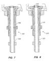
- the vial 181 is filled with a reagent solution through the top opening 610. Then, during the purging process, the vial 181 is drained of the reagent solution through the bottom opening 640.
- the frit 620 prevents the CPG 650 or other support from being flushed away during the purging process.
- a precision bored interior 630 holds the frit 620 in place and provides a consistent compression and seal with the frit 620. As a result of the precision bored interior 630, there is a consistent flow of the reagent solution through each vial during both the dispensing and purging processes.
- each vial 181 also has a precise dimension around the support 660.
- This support 660 fits within the receiving hole 185 within the cartridge 170 and provides a pressure tight seal around each vial within the cartridge 170.
- each vial 181 is formed of polyethylene by a molded process.
- the vials 181 can be formed using any appropriate process and any appropriate material.
- the controller 480 which is coupled to the motor 445, the valves 470, and the waste tube system 430 coordinates the operation of the synthesizer 100.
- the controller 480 controls the motor 445 such that the cartridge is rotated to align the correct vials with the dispense lines 140 corresponding to the appropriate valves 470 during dispensing operations and that the correct one of the drains 740, 750. 760 and 770. are aligned with an appropriate waste tube system 430 during a flushing operation.
- the computer system 800 instructs the synthesizer 100 to perform appropriate functions without any further input from the user.
- the computer system 800 preferably includes a processor 810, an input device 820 and a display 830.
- the computer 800 can be configured as a laptop or a desktop.
- a dispense operation could also be performed on vials other than the bank or banks of vials being purged, if the position of the vials corresponds to the appropriate valves.
- the cartridge 170 cannot be rotated or the drain 740 will disengage from the mobile waste tube 500.
- the motor 445 rotates the cartridge 170 in response to the computer system 800 such that the vial 181 is positioned below the appropriate dispense line 140 corresponding to the valve 470.
- the valve is opened by the controller 480 and the solution controlled by the valve 470 flows through the dispense tube 140 into the vial 181.
- the valve 470 is then closed after a predetermined period of time corresponding to the precise amount of solution to be dispensed into the vial 181.
- the motor 445 rotates the cartridge 170 in response to the computer system 800 such that the drain corresponding to the bank of vials to be purged is positioned above the waste tube system 430.
- the mobile waste tube 500 is then raised to engage the drain and the material within the bank of vials is expelled from the vials through the waste tube system 430.
Applications Claiming Priority (3)
| Application Number | Priority Date | Filing Date | Title |
|---|---|---|---|
| US09/097,966 US6270730B1 (en) | 1998-06-16 | 1998-06-16 | Multi-well rotary synthesizer |
| US97966 | 1998-06-16 | ||
| PCT/US1999/013582 WO1999065602A2 (en) | 1998-06-16 | 1999-06-15 | Multi-well rotary synthesizer |
Publications (2)
| Publication Number | Publication Date |
|---|---|
| EP1094892A2 EP1094892A2 (en) | 2001-05-02 |
| EP1094892B1 true EP1094892B1 (en) | 2005-10-26 |
Family
ID=22265962
Family Applications (1)
| Application Number | Title | Priority Date | Filing Date |
|---|---|---|---|
| EP99930312A Expired - Lifetime EP1094892B1 (en) | 1998-06-16 | 1999-06-15 | Vial and Multi-well Rotary Synthesizer |
Country Status (7)
| Country | Link |
|---|---|
| US (9) | US6270730B1 (ja) |
| EP (1) | EP1094892B1 (ja) |
| JP (1) | JP4338311B2 (ja) |
| AU (1) | AU748030B2 (ja) |
| CA (1) | CA2331809C (ja) |
| DE (1) | DE69927975T2 (ja) |
| WO (1) | WO1999065602A2 (ja) |
Families Citing this family (29)
| Publication number | Priority date | Publication date | Assignee | Title |
|---|---|---|---|---|
| US6270730B1 (en) * | 1998-06-16 | 2001-08-07 | Northwest Engineering Inc. | Multi-well rotary synthesizer |
| US6264891B1 (en) * | 1998-12-22 | 2001-07-24 | Eos Biotechnology, Inc. | Apparatus and method for concurrent chemical synthesis |
| DE59906395D1 (de) | 1998-12-30 | 2003-08-28 | Mwg Biotech Ag | Vorrichtung zur durchführung von chemischen reaktionen |
| DE19919607A1 (de) * | 1999-04-29 | 2000-11-16 | Mets Ion Gmbh Ges Fuer Angewan | Verfahren und Vorrichtung zur parallelen Herstellung von wenigstens 4n Oligonukleotiden |
| AU2002224339A1 (en) * | 2000-10-03 | 2002-04-15 | Gary R. Mcluen | Multi-well rotary synthesizer with sealing waste tube system |
| US6932943B1 (en) | 2001-01-26 | 2005-08-23 | Third Wave Technologies | Nucleic acid synthesizers |
| US7435390B2 (en) * | 2001-01-26 | 2008-10-14 | Third Wave Technologies, Inc. | Nucleic acid synthesizers |
| US20080261220A1 (en) * | 2000-11-30 | 2008-10-23 | Third Wave Technologies, Inc. | Nucleic Acid Detection Assays |
| US20030072689A1 (en) * | 2001-08-15 | 2003-04-17 | Third Wave Technologies, Inc. | Polymer synthesizer |
| WO2002089670A1 (en) * | 2001-05-10 | 2002-11-14 | Chempaq A/S | Device for sampling small and precise volumes of liquid |
| WO2005058471A2 (en) * | 2003-12-15 | 2005-06-30 | Applera Corporation | Automated oligomer synthesis |
| US7581678B2 (en) | 2005-02-22 | 2009-09-01 | Tyfone, Inc. | Electronic transaction card |
| US8663575B2 (en) | 2005-08-19 | 2014-03-04 | Canadian Blood Services | Sample holder for dynamic light scattering |
| EP1937400A4 (en) * | 2005-09-14 | 2011-02-23 | Illumina Inc | DEVICE FOR THE CONTINUOUS SYNTHESIS OF POLYMERS |
| EP1785190A1 (en) | 2005-11-09 | 2007-05-16 | JEPSEN, Peter | Synthesis apparatus having rotatable, interchangeable reaction holders |
| US20070110637A1 (en) * | 2005-11-11 | 2007-05-17 | Phelps David Y | Automated rotary synthesizer |
| WO2008138337A2 (en) * | 2007-05-09 | 2008-11-20 | Alcorlab A/S | An oligo peptide synthesis and a cleavage and evaporation apparatus |
| US8451122B2 (en) | 2008-08-08 | 2013-05-28 | Tyfone, Inc. | Smartcard performance enhancement circuits and systems |
| US20110021749A1 (en) * | 2009-07-27 | 2011-01-27 | Demmitt Thomas J | Chemical Plugs used with Automated Organic Polymer Synthesizers |
| WO2012162101A1 (en) * | 2011-05-20 | 2012-11-29 | Geneforge, Inc. | Drop-in nozzle |
| US8673628B2 (en) | 2011-06-10 | 2014-03-18 | Essen Instruments, Inc. | Methods and apparatus for improving in vitro measurements using boyden chambers |
| US9069358B2 (en) | 2013-06-24 | 2015-06-30 | Biolytic Lab Performance, Inc. | System for controlling and optimizing reactions in solid phase synthesis of small molecules |
| US10040048B1 (en) | 2014-09-25 | 2018-08-07 | Synthego Corporation | Automated modular system and method for production of biopolymers |
| US20190086324A1 (en) * | 2016-03-23 | 2019-03-21 | Truvian Sciences, Inc. | Systems and Methods for Multianalyte Detection |
| CN110709161A (zh) | 2017-03-29 | 2020-01-17 | 东丽工程株式会社 | 合成装置和计量机构 |
| JP6872454B2 (ja) * | 2017-08-03 | 2021-05-19 | 東レエンジニアリング株式会社 | 薬液合成装置 |
| GB2582865B (en) * | 2017-09-11 | 2022-05-04 | Synthego Corp | Biopolymer synthesis system and method |
| US11666882B2 (en) | 2020-06-26 | 2023-06-06 | Biolytic Lab Performance, Inc. | Bidirectional flow reaction system for solid phase synthesis |
| US11473699B2 (en) | 2020-06-26 | 2022-10-18 | Biolytic Lab Performance, Inc | Tubing support system |
Family Cites Families (137)
| Publication number | Priority date | Publication date | Assignee | Title |
|---|---|---|---|---|
| US2434167A (en) | 1945-05-23 | 1948-01-06 | Ernest O Knoblauch | Valved coupling |
| US2684255A (en) | 1949-12-15 | 1954-07-20 | Joseph B Abele | Joint seal structure |
| FR1143849A (fr) | 1956-02-25 | 1957-10-04 | Perfectionnements apportés aux systèmes d'obturation, notamment pour vidanges d'appareils sanitaires, ménagers ou analogues | |
| US3215500A (en) * | 1961-06-12 | 1965-11-02 | Donald L Bittner | Laboratory mixer-separator |
| US3583230A (en) * | 1968-06-12 | 1971-06-08 | Sondell Research Dev Co | Sample injection method and apparatus |
| US3538950A (en) | 1969-04-16 | 1970-11-10 | Locking Devices Inc | Quick connect lugged coupling |
| BE758245A (fr) * | 1969-11-03 | 1971-04-30 | Hoffmann La Roche | Pipette de precision |
| US3838013A (en) * | 1971-04-01 | 1974-09-24 | Gen Electric | Combined sampling and bacteriological culturing device |
| US3844306A (en) * | 1973-03-07 | 1974-10-29 | R Hill | Gas supply system |
| HU168257B (ja) | 1973-05-18 | 1976-03-28 | ||
| AU1414976A (en) | 1975-05-21 | 1977-11-24 | Mobil Oil Australia | Drain valve |
| US4114853A (en) * | 1976-10-08 | 1978-09-19 | Swagelok Company | Quick connect coupling |
| US4090850A (en) * | 1976-11-01 | 1978-05-23 | E. R. Squibb & Sons, Inc. | Apparatus for use in radioimmunoassays |
| US4458066A (en) | 1980-02-29 | 1984-07-03 | University Patents, Inc. | Process for preparing polynucleotides |
| US5132418A (en) | 1980-02-29 | 1992-07-21 | University Patents, Inc. | Process for preparing polynucleotides |
| US4353989A (en) * | 1981-01-19 | 1982-10-12 | Ens Bio Logicals Inc. | Chemical synthesis apparatus for preparation of polynucleotides |
| US4415732A (en) | 1981-03-27 | 1983-11-15 | University Patents, Inc. | Phosphoramidite compounds and processes |
| US4360360A (en) * | 1981-04-02 | 1982-11-23 | Baxter Travenol Laboratories, Inc. | Centrifugal analyzer |
| SE8102316L (sv) * | 1981-04-10 | 1982-10-11 | Pharmacia Diagnostics Ab | Anordning for genomforande av analyser |
| JPS6054398A (ja) | 1983-09-02 | 1985-03-28 | Nippon Zeon Co Ltd | ポリヌクレオチド合成装置 |
| US4668476A (en) | 1984-03-23 | 1987-05-26 | Applied Biosystems, Inc. | Automated polypeptide synthesis apparatus |
| US4849077A (en) | 1984-08-06 | 1989-07-18 | Akademie Der Wissenschaften Der Ddr | Process for solid phase-sequencing of nucleic acid fragments |
| JPH0690211B2 (ja) | 1984-09-21 | 1994-11-14 | オリンパス光学工業株式会社 | 免疫学的分析装置およびその方法 |
| US5096807A (en) | 1985-03-06 | 1992-03-17 | Murex Corporation | Imaging immunoassay detection system with background compensation and its use |
| US4753775A (en) * | 1985-04-12 | 1988-06-28 | E. I. Du Pont De Nemours And Company | Rapid assay processor |
| US5563033A (en) | 1985-10-22 | 1996-10-08 | The University Of Massachusetts Medical Center | Detection of individual gene transcription |
| US5468606A (en) | 1989-09-18 | 1995-11-21 | Biostar, Inc. | Devices for detection of an analyte based upon light interference |
| US4810471A (en) | 1986-07-24 | 1989-03-07 | Rohm And Haas Co. | Vacuum manifold for extraction processing |
| US4859419A (en) * | 1987-02-27 | 1989-08-22 | American Bionetics, Inc. | Diagnostic manifold apparatus |
| US4748859A (en) | 1987-03-06 | 1988-06-07 | Rainin Instrument Co., Inc. | Disposable pipette tip |
| US4849648A (en) * | 1987-08-24 | 1989-07-18 | Columbia Energy Storage, Inc. | Compressed gas system and method |
| US4874691A (en) * | 1987-10-16 | 1989-10-17 | Quadra Logic Technologies Inc. | Membrane-supported immunoassays |
| US4875691A (en) * | 1988-02-05 | 1989-10-24 | Westinghouse Electric Corp. | Radial seal |
| US5239484A (en) | 1988-03-31 | 1993-08-24 | Takeda Chemical Industries, Ltd. | Automatic synthesis apparatus |
| US5093268A (en) | 1988-04-28 | 1992-03-03 | Igen, Inc. | Apparatus for conducting a plurality of simultaneous measurements of electrochemiluminescent phenomena |
| US5147608A (en) | 1988-04-29 | 1992-09-15 | Millipore Corporation | Apparatus and process for performing repetitive chemical processing |
| US5720928A (en) | 1988-09-15 | 1998-02-24 | New York University | Image processing and analysis of individual nucleic acid molecules |
| US5047524A (en) | 1988-12-21 | 1991-09-10 | Applied Biosystems, Inc. | Automated system for polynucleotide synthesis and purification |
| US5262530A (en) | 1988-12-21 | 1993-11-16 | Applied Biosystems, Inc. | Automated system for polynucleotide synthesis and purification |
| US5053454A (en) * | 1989-02-15 | 1991-10-01 | Sri International | Multiple polymer synthesizer |
| US5648266A (en) * | 1989-02-24 | 1997-07-15 | Astle; Thomas W. | Cell harvester system |
| DE3908725A1 (de) | 1989-03-14 | 1990-09-20 | Schering Ag | Automatisch arbeitende vorrichtung zur gleichzeitigen und standardisierten durchfuehrung einer anzahl chemischer, physikalisch-chemischer oder biologischer arbeitsverfahren |
| US5066600A (en) | 1989-05-19 | 1991-11-19 | Cummins Engine Company, Inc. | Multiple waste isolation system |
| US5744101A (en) | 1989-06-07 | 1998-04-28 | Affymax Technologies N.V. | Photolabile nucleoside protecting groups |
| US5547839A (en) | 1989-06-07 | 1996-08-20 | Affymax Technologies N.V. | Sequencing of surface immobilized polymers utilizing microflourescence detection |
| US5143854A (en) | 1989-06-07 | 1992-09-01 | Affymax Technologies N.V. | Large scale photolithographic solid phase synthesis of polypeptides and receptor binding screening thereof |
| US5112736A (en) | 1989-06-14 | 1992-05-12 | University Of Utah | Dna sequencing using fluorescence background electroblotting membrane |
| US5101673A (en) | 1989-07-24 | 1992-04-07 | Tritech Partners | Ultra low sample liquid analysis apparatus and method |
| US5437979A (en) | 1989-07-24 | 1995-08-01 | Beckman Instruments, Inc. | Solid phase system for sequential reactions |
| US5297288A (en) | 1989-11-28 | 1994-03-22 | United States Biochemical Corporation | System for use with a high resolution scanner for scheduling a sequence of software tools for determining the presence of bands in DNA sequencing samples |
| US5250040A (en) | 1989-12-21 | 1993-10-05 | Medical Innovations Corporation | Ferrule and enteral tube incorporating a ferrule |
| US5822601A (en) * | 1989-12-29 | 1998-10-13 | Packard Bell Nec | Apparatus to allow a CPU to control the relocation of code blocks for other CPUs |
| US5427930A (en) | 1990-01-26 | 1995-06-27 | Abbott Laboratories | Amplification of target nucleic acids using gap filling ligase chain reaction |
| DE4005518A1 (de) | 1990-02-22 | 1991-08-29 | Boehringer Ingelheim Kg | Verfahren und vorrichtung zur simultanen synthese mehrerer polypeptide |
| US5048578A (en) * | 1990-03-01 | 1991-09-17 | Arkady Dorf | Oil drainage coupler |
| US5288644A (en) | 1990-04-04 | 1994-02-22 | The Rockefeller University | Instrument and method for the sequencing of genome |
| US5252296A (en) | 1990-05-15 | 1993-10-12 | Chiron Corporation | Method and apparatus for biopolymer synthesis |
| SE9002579D0 (sv) | 1990-08-07 | 1990-08-07 | Pharmacia Ab | Method and apparatus for carrying out biochemical reactions |
| US5171537A (en) | 1991-05-06 | 1992-12-15 | Richard E. MacDonald | Activated immunodiagnostic pipette tips |
| US5192511A (en) | 1991-05-31 | 1993-03-09 | Tri-Continent Scientific, Inc. | Pipette tip and piston |
| JPH0720546B2 (ja) | 1991-08-26 | 1995-03-08 | 株式会社島津製作所 | 多種品目同時化学反応装置 |
| JP3123249B2 (ja) | 1991-09-10 | 2001-01-09 | 株式会社日立製作所 | Dna分子の長さ計測方法および計測装置 |
| US5605662A (en) | 1993-11-01 | 1997-02-25 | Nanogen, Inc. | Active programmable electronic devices for molecular biological analysis and diagnostics |
| US5632957A (en) | 1993-11-01 | 1997-05-27 | Nanogen | Molecular biological diagnostic systems including electrodes |
| US5846708A (en) | 1991-11-19 | 1998-12-08 | Massachusetts Institiute Of Technology | Optical and electrical methods and apparatus for molecule detection |
| US5240680A (en) * | 1991-12-19 | 1993-08-31 | Chiron Corporation | Automated apparatus for use in peptide synthesis |
| JPH0734910Y2 (ja) | 1992-01-29 | 1995-08-09 | 株式会社島津製作所 | 固相法ペプチド合成器 |
| US5354537A (en) | 1992-04-27 | 1994-10-11 | Akzo N.V. | Piercing and sampling probe |
| US5645114A (en) | 1992-05-11 | 1997-07-08 | Cytologix Corporation | Dispensing assembly with interchangeable cartridge pumps |
| US5483843A (en) | 1992-06-01 | 1996-01-16 | Thermo Separation Products Inc. | Transport apparatus |
| WO1994001215A1 (en) | 1992-07-06 | 1994-01-20 | Beckman Instruments, Inc. | Fluid delivery system utilizing multiple port valve |
| DE69305947T2 (de) * | 1992-09-18 | 1997-03-13 | Amersham Int Plc | Vorrichtung und Methode zur Affinitätstrennung |
| CH684554A5 (de) * | 1992-09-22 | 1994-10-14 | Sotax Ag | Probensammler. |
| US5324483B1 (en) | 1992-10-08 | 1996-09-24 | Warner Lambert Co | Apparatus for multiple simultaneous synthesis |
| WO1994016104A1 (en) | 1993-01-08 | 1994-07-21 | Ctrc Research Foundation | Color imaging system for use in molecular biology |
| US5368823A (en) * | 1993-02-11 | 1994-11-29 | University Of Georgia Research Foundation, Inc. | Automated synthesis of oligonucleotides |
| ATE208658T1 (de) | 1993-07-28 | 2001-11-15 | Pe Corp Ny | Vorrichtung und verfahren zur nukleinsäurevervielfältigung |
| US5380495A (en) * | 1993-08-27 | 1995-01-10 | Chang; Heng-Wei | Solid phase peptide synthesizer |
| US5541113A (en) | 1993-09-22 | 1996-07-30 | Beckman Instruments, Inc. | Method for detecting an analyte using an electrochemical luminescent transition metal label |
| US5472842A (en) | 1993-10-06 | 1995-12-05 | The Regents Of The University Of California | Detection of amplified or deleted chromosomal regions |
| US5597694A (en) | 1993-10-07 | 1997-01-28 | Massachusetts Institute Of Technology | Interspersed repetitive element-bubble amplification of nucleic acids |
| US5645801A (en) | 1993-10-21 | 1997-07-08 | Abbott Laboratories | Device and method for amplifying and detecting target nucleic acids |
| US5472672A (en) | 1993-10-22 | 1995-12-05 | The Board Of Trustees Of The Leland Stanford Junior University | Apparatus and method for polymer synthesis using arrays |
| US5503805A (en) | 1993-11-02 | 1996-04-02 | Affymax Technologies N.V. | Apparatus and method for parallel coupling reactions |
| US5522272A (en) | 1993-11-04 | 1996-06-04 | Bellaire Industries, Inc. | Gas emission sample container with heating means |
| WO1997026540A1 (en) | 1994-03-11 | 1997-07-24 | Barrskogen, Inc. | Minifiltration method and apparatus |
| US5496523A (en) | 1994-05-06 | 1996-03-05 | Sorenson Bioscience | Filtered micropipette tip for high/low volume pipettors |
| US5571639A (en) | 1994-05-24 | 1996-11-05 | Affymax Technologies N.V. | Computer-aided engineering system for design of sequence arrays and lithographic masks |
| US5639428A (en) | 1994-07-19 | 1997-06-17 | Becton Dickinson And Company | Method and apparatus for fully automated nucleic acid amplification, nucleic acid assay and immunoassay |
| US5639426A (en) | 1994-08-31 | 1997-06-17 | Bayer Corporation | Sample liquid aspiration and dispensing probe |
| SE503198C2 (sv) * | 1994-09-20 | 1996-04-15 | Gambro Ab | Förfarande och anordning för central preparering av ett saltkoncentrat jämte förfarande för desinficering av anordningen och behållare avsedd för anordningen |
| EP0738395A1 (fr) | 1994-11-07 | 1996-10-23 | Laboratoires Merck-Clevenot | Appareil automatique de dosage immunologique |
| DE19546952C2 (de) | 1994-12-17 | 1999-06-17 | Horiba Ltd | Gasanalysator-Einschubanordnung |
| US5575914A (en) | 1994-12-23 | 1996-11-19 | Vance Products Incorporated | Sperm filter trap having compressed glass wool filter material |
| DE29505652U1 (de) | 1995-04-01 | 1996-04-25 | Boehringer Mannheim Gmbh | Gefäß zur kontaminationsreduzierten Behandlung von Flüssigkeiten |
| US6171555B1 (en) * | 1995-04-17 | 2001-01-09 | Ontogen Corporation | Reaction block docking station |
| US5609826A (en) * | 1995-04-17 | 1997-03-11 | Ontogen Corporation | Methods and apparatus for the generation of chemical libraries |
| US5690894A (en) | 1995-05-23 | 1997-11-25 | The Regents Of The University Of California | High density array fabrication and readout method for a fiber optic biosensor |
| US5545531A (en) | 1995-06-07 | 1996-08-13 | Affymax Technologies N.V. | Methods for making a device for concurrently processing multiple biological chip assays |
| US5736333A (en) | 1996-06-04 | 1998-04-07 | The Perkin-Elmer Corporation | Passive internal references for the detection of nucleic acid amplification products |
| EP0913465A4 (en) * | 1996-06-28 | 2001-04-18 | Kasen Nozzle Mfg Co Ltd | AUTOMATIC TEST APPARATUS |
| US5807523A (en) * | 1996-07-03 | 1998-09-15 | Beckman Instruments, Inc. | Automatic chemistry analyzer |
| US5792430A (en) * | 1996-08-12 | 1998-08-11 | Monsanto Company | Solid phase organic synthesis device with pressure-regulated manifold |
| JP2001500426A (ja) | 1996-09-12 | 2001-01-16 | カイロン コーポレイション | モジュラー反応容器の配列を含む固相化学合成における使用のための作動手段 |
| US5798035A (en) * | 1996-10-03 | 1998-08-25 | Pharmacopeia, Inc. | High throughput solid phase chemical synthesis utilizing thin cylindrical reaction vessels useable for biological assay |
| DE19642777A1 (de) | 1996-10-16 | 1998-05-28 | Vetter Dirk Dr | Reaktor für mikrochemische bzw. mikrobiologische Synthesen |
| US5762881A (en) | 1996-10-29 | 1998-06-09 | Bohdan Automation, Inc. | Apparatus for multiple, simultaneous synthesis of organic compounds |
| US6274094B1 (en) | 1997-01-13 | 2001-08-14 | Weller, Iii Harold Norris | Nestable, modular apparatus for synthesis of multiple organic compounds |
| US6123905A (en) | 1997-01-17 | 2000-09-26 | Matrix Technologies Corporation | Pipettor including an indicator and method of use |
| US6495624B1 (en) | 1997-02-03 | 2002-12-17 | Cytonix Corporation | Hydrophobic coating compositions, articles coated with said compositions, and processes for manufacturing same |
| JP2001511794A (ja) * | 1997-02-17 | 2001-08-14 | ゲゼルシャフト・フュア・ビオテヒノロジッシェ・フォルシュング・エムベーハー(ゲー・ベー・エフ) | 自動化学合成装置 |
| GB9703779D0 (en) | 1997-02-24 | 1997-04-16 | Oxford Asymmetry Ltd | Reaction apparatus and method of using the same |
| US6048457A (en) | 1997-02-26 | 2000-04-11 | Millipore Corporation | Cast membrane structures for sample preparation |
| US6126904A (en) | 1997-03-07 | 2000-10-03 | Argonaut Technologies, Inc. | Apparatus and methods for the preparation of chemical compounds |
| US5861094A (en) | 1997-04-17 | 1999-01-19 | Goehde; Wolfgang | Filter for biological particle separation |
| US6890491B1 (en) | 1997-06-10 | 2005-05-10 | Pharmacopeia Drug Discovery, Inc. | Method and apparatus for universal fluid exchange |
| US5851491A (en) | 1997-06-13 | 1998-12-22 | Labcon, North America | Pipette tip and filter for accurate sampling and prevention of contamination |
| US5882601A (en) | 1997-06-18 | 1999-03-16 | Merck & Co., Ltd. | Deflected septum seal access port |
| DE29719919U1 (de) | 1997-11-10 | 1999-04-01 | Jung Guenther Prof Dr | Reaktoreinheit zur parallelen Durchführung einer Vielzahl chemischer Reaktionen |
| US6083682A (en) * | 1997-12-19 | 2000-07-04 | Glaxo Group Limited | System and method for solid-phase parallel synthesis of a combinatorial collection of compounds |
| US6133045A (en) * | 1998-02-27 | 2000-10-17 | Hamilton Company | Automated sample treatment system: apparatus and method |
| US6537504B1 (en) | 1998-04-06 | 2003-03-25 | Li Young | Method and apparatus for concurrent and sequential multi-step reactions for producing a plurality of different chemical compounds |
| US5976470A (en) | 1998-05-29 | 1999-11-02 | Ontogen Corporation | Sample wash station assembly |
| US6270730B1 (en) | 1998-06-16 | 2001-08-07 | Northwest Engineering Inc. | Multi-well rotary synthesizer |
| US6319236B1 (en) | 1998-11-06 | 2001-11-20 | Millipore Corporation | Universal outlet for filter units |
| US6264891B1 (en) * | 1998-12-22 | 2001-07-24 | Eos Biotechnology, Inc. | Apparatus and method for concurrent chemical synthesis |
| US6485690B1 (en) | 1999-05-27 | 2002-11-26 | Orchid Biosciences, Inc. | Multiple fluid sample processor and system |
| US6225109B1 (en) * | 1999-05-27 | 2001-05-01 | Orchid Biosciences, Inc. | Genetic analysis device |
| DE10002475C1 (de) | 2000-01-21 | 2001-05-31 | Roche Diagnostics Gmbh | Analysegerät zur Analyse von Proben |
| US6566145B2 (en) | 2000-02-09 | 2003-05-20 | William E Brewer | Disposable pipette extraction |
| US6432365B1 (en) * | 2000-04-14 | 2002-08-13 | Discovery Partners International, Inc. | System and method for dispensing solution to a multi-well container |
| US6361963B1 (en) * | 2000-08-02 | 2002-03-26 | Hercules Incorporated | Biofilm growth device |
| US7435390B2 (en) | 2001-01-26 | 2008-10-14 | Third Wave Technologies, Inc. | Nucleic acid synthesizers |
| US6491873B2 (en) * | 2001-01-23 | 2002-12-10 | Varian, Inc. | Multi-well filtration apparatus |
| US20030086829A1 (en) | 2001-10-24 | 2003-05-08 | Livesay Eric A. | High throughput chemical synthesizer |
| US6893613B2 (en) | 2002-01-25 | 2005-05-17 | Bristol-Myers Squibb Company | Parallel chemistry reactor with interchangeable vessel carrying inserts |
| JP5504147B2 (ja) | 2010-12-21 | 2014-05-28 | 株式会社荏原製作所 | 電気めっき方法 |
-
1998
- 1998-06-16 US US09/097,966 patent/US6270730B1/en not_active Expired - Lifetime
-
1999
- 1999-06-15 EP EP99930312A patent/EP1094892B1/en not_active Expired - Lifetime
- 1999-06-15 AU AU46874/99A patent/AU748030B2/en not_active Ceased
- 1999-06-15 DE DE69927975T patent/DE69927975T2/de not_active Expired - Lifetime
- 1999-06-15 CA CA002331809A patent/CA2331809C/en not_active Expired - Lifetime
- 1999-06-15 JP JP2000554472A patent/JP4338311B2/ja not_active Expired - Lifetime
- 1999-06-15 WO PCT/US1999/013582 patent/WO1999065602A2/en active IP Right Grant
-
2000
- 2000-12-19 US US09/742,803 patent/US8158085B2/en not_active Expired - Fee Related
- 2000-12-19 US US09/742,460 patent/US7150998B2/en not_active Expired - Lifetime
- 2000-12-19 US US09/742,261 patent/US7192558B2/en not_active Expired - Lifetime
-
2001
- 2001-07-09 US US09/901,949 patent/US6811755B2/en not_active Expired - Lifetime
-
2008
- 2008-05-27 US US12/154,880 patent/US8147776B2/en not_active Expired - Fee Related
-
2012
- 2012-02-28 US US13/406,782 patent/US8404196B2/en not_active Expired - Fee Related
-
2013
- 2013-02-25 US US13/776,506 patent/US8747780B2/en not_active Expired - Fee Related
-
2014
- 2014-05-21 US US14/284,108 patent/US20140255277A1/en not_active Abandoned
Also Published As
| Publication number | Publication date |
|---|---|
| US20010051114A1 (en) | 2001-12-13 |
| JP2002518526A (ja) | 2002-06-25 |
| US8147776B2 (en) | 2012-04-03 |
| EP1094892A2 (en) | 2001-05-02 |
| US6270730B1 (en) | 2001-08-07 |
| US20130164196A1 (en) | 2013-06-27 |
| US20010001035A1 (en) | 2001-05-10 |
| CA2331809A1 (en) | 1999-12-23 |
| JP4338311B2 (ja) | 2009-10-07 |
| US7192558B2 (en) | 2007-03-20 |
| AU4687499A (en) | 2000-01-05 |
| US6811755B2 (en) | 2004-11-02 |
| US8747780B2 (en) | 2014-06-10 |
| US20140255277A1 (en) | 2014-09-11 |
| CA2331809C (en) | 2008-11-18 |
| DE69927975T2 (de) | 2006-07-27 |
| WO1999065602A2 (en) | 1999-12-23 |
| US20090263289A1 (en) | 2009-10-22 |
| US20010000723A1 (en) | 2001-05-03 |
| US7150998B2 (en) | 2006-12-19 |
| US8404196B2 (en) | 2013-03-26 |
| WO1999065602A3 (en) | 2000-06-15 |
| US8158085B2 (en) | 2012-04-17 |
| AU748030B2 (en) | 2002-05-30 |
| US20010007644A1 (en) | 2001-07-12 |
| DE69927975D1 (de) | 2005-12-01 |
| US20120171088A1 (en) | 2012-07-05 |
Similar Documents
| Publication | Publication Date | Title |
|---|---|---|
| US8747780B2 (en) | Multi-well rotary synthesizer | |
| US6264891B1 (en) | Apparatus and method for concurrent chemical synthesis | |
| AU5486996A (en) | Methods and apparatus for the generation of chemical libraries | |
| US20150369267A1 (en) | Well drain system for use with multi-well synthesizer | |
| CA2746074C (en) | Polymer synthesizer | |
| CA2614880C (en) | Vial | |
| AU775106B2 (en) | A vial | |
| WO2002028524A2 (en) | Multi-well rotary synthesizer with sealing waste tube system | |
| EP3495038B1 (en) | Device for parallel oligomer synthesis, method of parallel oligomer synthesis and use thereof | |
| WO2012048270A1 (en) | Well drain system for use with multi-well synthesizer | |
| AU2004202302A1 (en) | Apparatus and Method for Concurrent Chemical Synthesis | |
| CZ280720B6 (cs) | Reaktor pro multisekvenční syntézu peptidů a knihoven peptidů |
Legal Events
| Date | Code | Title | Description |
|---|---|---|---|
| PUAI | Public reference made under article 153(3) epc to a published international application that has entered the european phase |
Free format text: ORIGINAL CODE: 0009012 |
|
| 17P | Request for examination filed |
Effective date: 20010108 |
|
| AK | Designated contracting states |
Kind code of ref document: A2 Designated state(s): CH DE FR GB IT LI SE |
|
| 17Q | First examination report despatched |
Effective date: 20010508 |
|
| RAP1 | Party data changed (applicant data changed or rights of an application transferred) |
Owner name: MCLUEN DESIGN, INC. |
|
| GRAP | Despatch of communication of intention to grant a patent |
Free format text: ORIGINAL CODE: EPIDOSNIGR1 |
|
| RTI1 | Title (correction) |
Free format text: VIAL AND MULTI-WELL ROTARY SYNTHESIZER |
|
| GRAS | Grant fee paid |
Free format text: ORIGINAL CODE: EPIDOSNIGR3 |
|
| GRAA | (expected) grant |
Free format text: ORIGINAL CODE: 0009210 |
|
| AK | Designated contracting states |
Kind code of ref document: B1 Designated state(s): CH DE FR GB IT LI SE |
|
| REG | Reference to a national code |
Ref country code: GB Ref legal event code: FG4D |
|
| REG | Reference to a national code |
Ref country code: CH Ref legal event code: NV Representative=s name: E. BLUM & CO. PATENTANWAELTE Ref country code: CH Ref legal event code: EP |
|
| REF | Corresponds to: |
Ref document number: 69927975 Country of ref document: DE Date of ref document: 20051201 Kind code of ref document: P |
|
| REG | Reference to a national code |
Ref country code: SE Ref legal event code: TRGR |
|
| ET | Fr: translation filed | ||
| PLBE | No opposition filed within time limit |
Free format text: ORIGINAL CODE: 0009261 |
|
| STAA | Information on the status of an ep patent application or granted ep patent |
Free format text: STATUS: NO OPPOSITION FILED WITHIN TIME LIMIT |
|
| 26N | No opposition filed |
Effective date: 20060727 |
|
| REG | Reference to a national code |
Ref country code: CH Ref legal event code: PFA Owner name: MCLUEN DESIGN, INC. Free format text: MCLUEN DESIGN, INC.#2023 SIMS WAY, 321#PORT TOWNSEND, WASHINGTON 98368 (US) -TRANSFER TO- MCLUEN DESIGN, INC.#2023 SIMS WAY, 321#PORT TOWNSEND, WASHINGTON 98368 (US) |
|
| PGFP | Annual fee paid to national office [announced via postgrant information from national office to epo] |
Ref country code: IT Payment date: 20090616 Year of fee payment: 11 |
|
| PGFP | Annual fee paid to national office [announced via postgrant information from national office to epo] |
Ref country code: CH Payment date: 20090615 Year of fee payment: 11 |
|
| PGFP | Annual fee paid to national office [announced via postgrant information from national office to epo] |
Ref country code: SE Payment date: 20090630 Year of fee payment: 11 Ref country code: GB Payment date: 20090610 Year of fee payment: 11 |
|
| REG | Reference to a national code |
Ref country code: CH Ref legal event code: PL |
|
| EUG | Se: european patent has lapsed | ||
| GBPC | Gb: european patent ceased through non-payment of renewal fee |
Effective date: 20100615 |
|
| REG | Reference to a national code |
Ref country code: FR Ref legal event code: ST Effective date: 20110228 |
|
| PG25 | Lapsed in a contracting state [announced via postgrant information from national office to epo] |
Ref country code: IT Free format text: LAPSE BECAUSE OF NON-PAYMENT OF DUE FEES Effective date: 20100615 |
|
| PG25 | Lapsed in a contracting state [announced via postgrant information from national office to epo] |
Ref country code: LI Free format text: LAPSE BECAUSE OF NON-PAYMENT OF DUE FEES Effective date: 20100630 Ref country code: CH Free format text: LAPSE BECAUSE OF NON-PAYMENT OF DUE FEES Effective date: 20100630 |
|
| PG25 | Lapsed in a contracting state [announced via postgrant information from national office to epo] |
Ref country code: FR Free format text: LAPSE BECAUSE OF NON-PAYMENT OF DUE FEES Effective date: 20100630 |
|
| PG25 | Lapsed in a contracting state [announced via postgrant information from national office to epo] |
Ref country code: GB Free format text: LAPSE BECAUSE OF NON-PAYMENT OF DUE FEES Effective date: 20100615 |
|
| PG25 | Lapsed in a contracting state [announced via postgrant information from national office to epo] |
Ref country code: SE Free format text: LAPSE BECAUSE OF NON-PAYMENT OF DUE FEES Effective date: 20100616 |
|
| PGFP | Annual fee paid to national office [announced via postgrant information from national office to epo] |
Ref country code: FR Payment date: 20090623 Year of fee payment: 11 |
|
| PGFP | Annual fee paid to national office [announced via postgrant information from national office to epo] |
Ref country code: DE Payment date: 20180605 Year of fee payment: 20 |
|
| REG | Reference to a national code |
Ref country code: DE Ref legal event code: R071 Ref document number: 69927975 Country of ref document: DE |