EP1094306A1 - Thermal flow sensor, method and apparatus for identifying fluid, flow sensor, and method and apparatus for flow measurement - Google Patents
Thermal flow sensor, method and apparatus for identifying fluid, flow sensor, and method and apparatus for flow measurement Download PDFInfo
- Publication number
- EP1094306A1 EP1094306A1 EP00917448A EP00917448A EP1094306A1 EP 1094306 A1 EP1094306 A1 EP 1094306A1 EP 00917448 A EP00917448 A EP 00917448A EP 00917448 A EP00917448 A EP 00917448A EP 1094306 A1 EP1094306 A1 EP 1094306A1
- Authority
- EP
- European Patent Office
- Prior art keywords
- flow rate
- fluid
- detected signal
- object fluid
- flow
- Prior art date
- Legal status (The legal status is an assumption and is not a legal conclusion. Google has not performed a legal analysis and makes no representation as to the accuracy of the status listed.)
- Withdrawn
Links
Images


Classifications
-
- G—PHYSICS
- G01—MEASURING; TESTING
- G01F—MEASURING VOLUME, VOLUME FLOW, MASS FLOW OR LIQUID LEVEL; METERING BY VOLUME
- G01F1/00—Measuring the volume flow or mass flow of fluid or fluent solid material wherein the fluid passes through a meter in a continuous flow
- G01F1/68—Measuring the volume flow or mass flow of fluid or fluent solid material wherein the fluid passes through a meter in a continuous flow by using thermal effects
-
- G—PHYSICS
- G01—MEASURING; TESTING
- G01N—INVESTIGATING OR ANALYSING MATERIALS BY DETERMINING THEIR CHEMICAL OR PHYSICAL PROPERTIES
- G01N27/00—Investigating or analysing materials by the use of electric, electrochemical, or magnetic means
- G01N27/02—Investigating or analysing materials by the use of electric, electrochemical, or magnetic means by investigating impedance
- G01N27/04—Investigating or analysing materials by the use of electric, electrochemical, or magnetic means by investigating impedance by investigating resistance
- G01N27/14—Investigating or analysing materials by the use of electric, electrochemical, or magnetic means by investigating impedance by investigating resistance of an electrically-heated body in dependence upon change of temperature
- G01N27/18—Investigating or analysing materials by the use of electric, electrochemical, or magnetic means by investigating impedance by investigating resistance of an electrically-heated body in dependence upon change of temperature caused by changes in the thermal conductivity of a surrounding material to be tested
-
- G—PHYSICS
- G01—MEASURING; TESTING
- G01F—MEASURING VOLUME, VOLUME FLOW, MASS FLOW OR LIQUID LEVEL; METERING BY VOLUME
- G01F1/00—Measuring the volume flow or mass flow of fluid or fluent solid material wherein the fluid passes through a meter in a continuous flow
- G01F1/68—Measuring the volume flow or mass flow of fluid or fluent solid material wherein the fluid passes through a meter in a continuous flow by using thermal effects
- G01F1/684—Structural arrangements; Mounting of elements, e.g. in relation to fluid flow
- G01F1/6845—Micromachined devices
-
- G—PHYSICS
- G01—MEASURING; TESTING
- G01F—MEASURING VOLUME, VOLUME FLOW, MASS FLOW OR LIQUID LEVEL; METERING BY VOLUME
- G01F1/00—Measuring the volume flow or mass flow of fluid or fluent solid material wherein the fluid passes through a meter in a continuous flow
- G01F1/68—Measuring the volume flow or mass flow of fluid or fluent solid material wherein the fluid passes through a meter in a continuous flow by using thermal effects
- G01F1/684—Structural arrangements; Mounting of elements, e.g. in relation to fluid flow
- G01F1/688—Structural arrangements; Mounting of elements, e.g. in relation to fluid flow using a particular type of heating, cooling or sensing element
- G01F1/6888—Thermoelectric elements, e.g. thermocouples, thermopiles
-
- G—PHYSICS
- G01—MEASURING; TESTING
- G01F—MEASURING VOLUME, VOLUME FLOW, MASS FLOW OR LIQUID LEVEL; METERING BY VOLUME
- G01F1/00—Measuring the volume flow or mass flow of fluid or fluent solid material wherein the fluid passes through a meter in a continuous flow
- G01F1/68—Measuring the volume flow or mass flow of fluid or fluent solid material wherein the fluid passes through a meter in a continuous flow by using thermal effects
- G01F1/684—Structural arrangements; Mounting of elements, e.g. in relation to fluid flow
- G01F1/688—Structural arrangements; Mounting of elements, e.g. in relation to fluid flow using a particular type of heating, cooling or sensing element
- G01F1/69—Structural arrangements; Mounting of elements, e.g. in relation to fluid flow using a particular type of heating, cooling or sensing element of resistive type
- G01F1/692—Thin-film arrangements
-
- G—PHYSICS
- G01—MEASURING; TESTING
- G01F—MEASURING VOLUME, VOLUME FLOW, MASS FLOW OR LIQUID LEVEL; METERING BY VOLUME
- G01F1/00—Measuring the volume flow or mass flow of fluid or fluent solid material wherein the fluid passes through a meter in a continuous flow
- G01F1/68—Measuring the volume flow or mass flow of fluid or fluent solid material wherein the fluid passes through a meter in a continuous flow by using thermal effects
- G01F1/696—Circuits therefor, e.g. constant-current flow meters
-
- G—PHYSICS
- G01—MEASURING; TESTING
- G01F—MEASURING VOLUME, VOLUME FLOW, MASS FLOW OR LIQUID LEVEL; METERING BY VOLUME
- G01F1/00—Measuring the volume flow or mass flow of fluid or fluent solid material wherein the fluid passes through a meter in a continuous flow
- G01F1/68—Measuring the volume flow or mass flow of fluid or fluent solid material wherein the fluid passes through a meter in a continuous flow by using thermal effects
- G01F1/696—Circuits therefor, e.g. constant-current flow meters
- G01F1/698—Feedback or rebalancing circuits, e.g. self heated constant temperature flowmeters
-
- G—PHYSICS
- G01—MEASURING; TESTING
- G01K—MEASURING TEMPERATURE; MEASURING QUANTITY OF HEAT; THERMALLY-SENSITIVE ELEMENTS NOT OTHERWISE PROVIDED FOR
- G01K1/00—Details of thermometers not specially adapted for particular types of thermometer
-
- G—PHYSICS
- G01—MEASURING; TESTING
- G01N—INVESTIGATING OR ANALYSING MATERIALS BY DETERMINING THEIR CHEMICAL OR PHYSICAL PROPERTIES
- G01N25/00—Investigating or analyzing materials by the use of thermal means
-
- G—PHYSICS
- G01—MEASURING; TESTING
- G01N—INVESTIGATING OR ANALYSING MATERIALS BY DETERMINING THEIR CHEMICAL OR PHYSICAL PROPERTIES
- G01N25/00—Investigating or analyzing materials by the use of thermal means
- G01N25/18—Investigating or analyzing materials by the use of thermal means by investigating thermal conductivity
-
- G—PHYSICS
- G01—MEASURING; TESTING
- G01N—INVESTIGATING OR ANALYSING MATERIALS BY DETERMINING THEIR CHEMICAL OR PHYSICAL PROPERTIES
- G01N33/00—Investigating or analysing materials by specific methods not covered by groups G01N1/00 - G01N31/00
- G01N33/22—Fuels; Explosives
Definitions
- This invention relates to a thermal fluid sensor which can be used to discriminate the kind of fluid, a fluid identifying apparatus and method for identifying the kind of an object fluid for measurement (simply referred to as object fluid or fluid) on the basis of a temperature detected signal produced from the fluid sensor, a flow velocity sensor (simply referred to as a flow sensor) which can be used for measurement of the flow rate, and a flow rate measuring apparatus and method for measuring the flow rate of the object fluid on the basis of a temperature detected signal.
- this invention relates to a flow sensor and a flow rate measuring apparatus and method which can measure the flow rate of the fluid accurately even when the kind and composition of the fluid are changed, and relates to a flow rate measuring apparatus and method which can measure the flow rate of the fluid even when the measuring range of the flow rate is relatively wide.
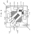
- a micro-flow sensor 101 includes an Si substrate 102, a diaphragm 103, a micro-heater 104, a downstream thermopile 105 formed on the diaphragm 103 at the lower end of the micro-heater 104, power source terminals 106A, 106B for supplying a driving current to the micro-heater 104, an upstream thermopile 108 formed on the diaphragm 103 at the upper end of the micro-heater 104, first output terminals 109A, 109B for producing a first temperature detected signal supplied from the upstream thermopile 108, and second output terminals 107A, 107B for producing a second temperature detected signal supplied from the downstream thermopile 105.
- the micro-heater 104 heats an object fluid for measurement such as a gas to generate uniform temperature distributions from itself to the downstream thermopile 105 and from itself to the upstream thermopile 108.
- a flow rate measuring apparatus (not shown) can measure the flow rate of the object fluid on the basis of a difference signal between the first temperature detected signal from the upstream thermopile 108 and the second temperature detected signal from the downstream thermopile 105.
- the conventional micro-flow sensor as shown in Fig. 9 has a disadvantage that when the kind or composition of the object fluid, the output characteristic is also changed.
- the physical property (hereinafter simply referred to as "property") of the fluid such as thermal conductivity, specific heat, viscosity, density, etc. is also changed. This modifies the temperature distribution of the fluid heated by the micro-heater, and hence the output characteristic.
- a gas analysis sensor was arranged, or otherwise the micro-flow sensor or a device incorporating it was caused to recognize the properties of the fluid previously.
- the gas having the same standard has a slightly different composition of the raw gas according to various lots.
- the gas composition for controlling the quantity of heat is adjusted with limited accuracy by a gas production factory so that the composition of the gas having the same standard may be changed. Therefore, there was a limit for the characteristic value of the fluid to be previously recognized by the micro-flow sensor and the device incorporating it.
- the gas meter is upsized, and the method for correcting the flow rate and the location of the gas analysis sensor must be considered. This makes it difficult to manufacture the gas meter at low cost.
- An object of this invention is to provide a thermal fluid sensor and fluid identifying apparatus and method which permits a flow sensor to measure the flow rate of an object fluid accurately even when the flow sensor produces a change in the output characteristic with a change in the kind or composition of an object fluid, and also provide the flow sensor and flow rate measuring apparatus and method which is preferably used to measure the flow rate using these thermal fluid sensor and fluid identifying apparatus and method.
- the thermal fluid sensor defined in claim 1 is characterized by comprising:
- the fluid discriminating apparatus defined in claim 6 for discriminating the kind of the object fluid using the thermal fluid sensor set force in claim 1 is characterized by comprising:
- the fluid discriminating apparatus defined in claim 10 for discriminating the kind of the object fluid using the thermal fluid sensor set forth in claim 1 is characterized by comprising:
- the fluid discriminating method defined in claim 11 of discriminating the object fluid using the thermal fluid sensor set forth in claim 1 is characterized by comprising:
- the flow rate measuring apparatus defined in claim 16 for measuring the flow rate of the object fluid flowing through the flow path using the thermal fluid sensor set forth in claim 1 is characterized by comprising:
- the flow rate measuring apparatus defined in claim 18 for measuring the flow rate of the object fluid flowing through the flow path using the thermal fluid sensor set forth in claim 1 is characterized by comprising:
- the flow rate measuring apparatus defined in claim 19 for measuring the flow rate of the object fluid flowing through the flow path using the thermal fluid sensor set forth in claim 1,
- the flow rate measuring method defined in claim 20 for measuring the flow rate of the object fluid flowing through the flow path using the thermal fluid sensor set forth in claim 1, is characterized by comprising:
- the flow rate measuring apparatus defined in claim 22 for measuring the flow rate of the object fluid flowing through the flow path using the thermal fluid sensor set forth in claim 1 is characterized by comprising:
- the flow sensor defined in claim 24 is characterized by comprising:
- the fluid discriminating apparatus defined in claim 31 for discriminating the kind of the object fluid using the thermal fluid sensor set force in claim 24 is characterized by comprising:
- the fluid discriminating apparatus defined in claim 32 according to claim 24 is characterized by comprising:
- the fluid discriminating apparatus defined in claim 34 for discriminating the kind of the object fluid using the flow sensor set forth in claim 24 is characterized by comprising:
- the fluid discriminating method defined in claim 35 for discriminating the kind of the object fluid using the flow sensor set force in claim 24 is characterized by comprising;
- the fluid discriminating method defined in claim 38 for discriminating the kind of the object fluid using the flow sensor set forth in claim 24 is characterized by comprising:
- the flow rate measuring apparatus defined in claim 41 for measuring the flow rate of the object fluid flowing through the flow path using the flow sensor set forth in claim 24 is characterized by comprising:
- the flow rate measuring apparatus defined in claim 42 for measuring the flow rate of the object fluid flowing through the flow path using the flow sensor set forth in claim 24,
- the flow rate measuring method defined in claim 43 for measuring the flow rate of the object fluid flowing through the flow path using the flow sensor set forth in claim 24 is characterized by comprising:
- the flow rate measuring apparatus defined in claim 46 for measuring the flow rate of the object fluid flowing through the flow path using the flow sensor set forth in claim 24 is characterized by comprising
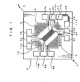
- a micro-flow sensor As seen from Fig. 1, a micro-flow sensor, generally 1 , includes a Si board 2, a diaphragm 3, a micro-heater 4 of Pt formed on the diaphragm 2, a downstream thermopile 5 formed downstream of the micro-heater 4 on the diaphragm 3, power source terminals 6A, 6B for supplying a driving current to the micro-heater 4 from a power source (not shown), an upstream thermopile 8 formed upstream of the micro-heater 4 on the diaphragm 3, first output terminals 9A, 9B for producing a first temperature detected signal supplied from the upstream thermopile 8, and second output terminals 7A, 7B for producing a second temperature detected signal supplied from the downstream thermopile 5.
- the micro-flow sensor 1 further includes a right thermopile 11, third output terminals 12A, 12B, a left thermopile 13 and fourth output terminals 14A, 14B.
- the right thermopile 11 is arranged in a direction orthogonal to the flow direction (direction from P to Q) of fluid with respect to the micro-heater 4 and serves to detect the property to produce a right temperature detected signal (corresponding to a third temperature detected signal).
- the third output terminals 12A, 12B provide the right temperature detected signal produced from the right thermopile 11.
- the left thermopile 13 is arranged in a direction orthogonal to the flow direction of fluid with respect to the micro-heater 4 and serves to detect the property to produce a left temperature detected signal (corresponding to a third temperature detected signal).
- the fourth output terminals 14A, 14B provide the left temperature detected signal produced from the left thermopile 13.
- the micro-flow sensor 1 further includes resistors 15, 16 used for acquiring the temperatures of the fluid and output terminals 17A, 17B for providing the fluid temperature signals produced from the resistors 15, 16.
- the right thermopile 11 and the left thermopile 13 constitute a temperature sensor.
- thermocouple 8 The upstream thermopile 8, downstream thermopile 5, right thermopile 11 and left thermopile 13 are constituted by a thermocouple, respectively.
- the thermocouple is made of p++ -Si and Al and has a cold contact and hot contact.
- the thermocouple detects heat to produce a temperature detected signal on the basis of the thermal electromotive force resulting from the temperature difference between the cold contact and the hot contact.
- the Si board 2 includes the diaphragm 2 on which the hot contact of each of the micro-heater 4, upstream thermopile 8, downstream thermopile 5, right thermopile 11 and left thermopile 13 is formed.
- thermopile 1 In the micro-flow sensor 1 thus configured, when the micro-heater 4 starts heating by the driving current externally supplied, the heat generated from the micro-heater 4 is conducted to the hot contact of each of the downstream thermopile 5 and the upstream thermopile 8 through the fluid.
- the cold contact of each of these thermopiles which is located on the Si board 2, exhibits the temperature of the board.
- the hot contact of each of these thermopiles, which is located on the diaphragm, is heated by the conducted heat.
- the hot contact has a temperature higher than that of the board 2.
- Each thermopile generates a thermal electromotive force based on the temperature difference between the hot contact and cold contact to produce a temperature detected signal.
- the heat conducted through the fluid is conducted to the respective thermopiles by the mutual effect of the thermal expansion of the fluid and the velocity of the fluid flowing from P to Q. More specifically, where there is no flow velocity, the heat is equally conducted to the upstream thermopile 8 and the downstream thermopile 5 by thermal expansion. Thus, the difference signal between the first temperature detected signal from the upstream thermopile 8 and the second temperature detected signal from the downstream thermopile 5 is zero.
- the difference signal between the second temperature detected signal and the first temperature detected signal is a positive value corresponding to the difference signal.
- the heat generated from the micro-heater 4 is conducted to the right thermopile 11 arranged in a direction orthogonal to the flow direction of the fluid with respect to the micro-heater 4 by only the thermal expansion without being affected by the flow velocity of the fluid.
- the heat generated from the micro-heater 4 is conducted to the left thermopile 13 arranged in a direction orthogonal to the flow direction of the fluid with respect to the micro-heater 4.
- the property of the fluid such as the thermal dispersion coefficient which is determined by thermal conduction, thermal dispersion, specific heat, etc.
- thermopile 11 can be computed on the basis of the right temperature detected signal produced from the third output terminals 12A, 12B by the electromotive force of the right thermopile 11 and/or the left temperature detected signal produced from the fourth output terminals 14A, 14B by the electromotive force of the left thermopile 13.
- thermopile 1 In the micro-flow sensor 1 according to this embodiment, the micro-heater 4, upstream thermopile 8, downstream thermopile 5, right thermopile 11 and left thermopile 13 are located on the diaphragm 3. Therefore, by reducing the thermal capacity of each of these elements, power consumption can be reduced.
- the micro-flow sensor 1, which is simple in structure, can be manufactured at low cost.
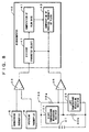
- Fig. 3 is a block diagram of the arrangement of a flow rate measuring apparatus using the micro-flow sensor according to the first embodiment of this invention.
- the flow rate measuring apparatus intends to measure the flow rate of the fluid such as gas.
- the flow rate measuring apparatus includes a differential amplifier 33 for amplifying the difference signal between the second temperature detected signal (from the downstream thermopile 5 within the micro-flow sensor 1) and the first temperature detected signal (from the upstream thermopile 8 within the micro-flow sensor 1), an amplifier 35a for amplifying the right temperature detected signal from the right thermopile 11 within the micro-flow sensor 1, an amplifier 35b for amplifying the left temperature detected signal from the left thermopile 11 within the micro-flow sensor 1 and a microcomputer 40.
- the microcomputer 40 includes an adder unit 45 for adding the right temperature detected signal produced from the amplifier 35a and the left temperature detected signal produced from the amplifier 35b, a divider unit for dividing the difference signal between the second temperature detected signal and the first temperature detected signal acquired by the differential amplifier 33 by an addition signal produced from the adder 45, a flow rate computing unit 41 for computing the flow rate of a fluid on the basis of an addition signal produced from the divider unit 47, and a fluid property computing unit 43 for computing the property such as the thermal conducting rate, specific heat, viscosity, density on the basis of the addition signal from the adder unit 45.
- step S11 when the micro-heater 4 is driven by the driving current of a pulse signal externally supplied (step S11), the second temperature detected signal is produced from the downstream thermopile 5, whereas the first temperature detected signal is produced from the upstream thermopile 8 (step S13). Both second and first temperature detected signals are supplied to the differential amplifier 33.
- Fig. 5 shows the response of the first and second temperature detected signals to the pulse signal.
- the differential amplifier 33 amplifies the second temperature detected signal from the downstream thermopile 5 and the first temperature detected signal from the upstream thermopile 8 (step S15).
- the adder unit 45 adds the right temperature detected signal supplied from the amplifier 35a and the left temperature detected signal supplied from the amplifier 35b to acquire an addition signal (step S17).
- Fig. 6 shows a timing chart of the right temperature detected signal, left temperature detected signal and addition signal.
- the divider unit 47 divides the difference signal after having amplified in step S15 by the addition signal acquired in step S17 to acquire a division signal (step S19).
- the flow rate computing unit 41 computes the precise flow rate of the fluid on the basis of the division signal acquired in step S19 (step S21).
- the fluid property computing unit 43 computes the property such as the thermal conducting rate, specific heat, viscosity, density of the fluid on the basis of the addition signal acquired in step S17 and the precise flow rate computed in step S21 (step S23).
- the thermal conductivity of the fluid is measured.
- the velocity of conducting heat through the fluid depends on the thermal diffusion coefficient (one of the properties of the fluid) which is determined by the thermal conducting coefficient, thermal diffusion and specific heat, etc.
- the thermal diffusion coefficient is acquired on the basis of the temperature difference between the left thermopile 13 or the right thermopile 14 and the micro-heater 4. The larger the temperature difference is, the smaller the thermal diffusion coefficient is.
- the value of the thermal diffusion coefficient affects the first temperature detected signal supplied from the upstream thermopile 8 and the second temperature detected signal supplied from the downstream thermopile 5. Namely, the values of these signals vary according to the thermal diffusion coefficient. Therefore, by dividing the first temperature detected signal, second temperature detected signal or the difference therebetween by the thermal diffusion coefficient, the precise flow rate can be computed for the fluids having different thermal diffusion coefficients, i.e. any kind of fluid.
- thermopile 8 also around the upstream thermopile 8 and the downstream thermopile 5, an increase in the thermal diffusion (reduction of the quantity of heat moving from the micro-heater 4) is generated like around the right thermopile 11 and the left thermopile 13. Therefore, when the quantity of heat of the fluid is increased, because of the attendant increase in the thermal diffusion, the difference between the temperature of the fluid around the downstream thermopile 5 and that around the upstream thermopile 8 is decreased.
- the difference signal between the second temperature detected signal (from the downstream thermopile 5) and the first temperature detected signal (from the upstream thermopile 8), which is to be essentially increased in proportion to an increase in the flow velocity of the fluid, is decreased under the influence of the thermal diffusion.
- the difference signal between the second temperature detected signal and the first temperature detected signal may be decreased although the flow rate has been increased.
- the ratio of the right temperature detected signal or the left temperature detected signal when the flow rate is not zero to the addition value is regarded as a coefficient representative of the changing rate of the quantity of moving heat. This coefficient is multiplied by the difference signal between the second temperature detected signal and the first temperature detected signal.
- the flow rate free from the influence of a change in the thermal diffusion can be computed, thereby acquiring the precise flow rate with high resolution.
- the difference signal between the first temperature detected signal and the second temperature detected signal after having been amplified, acquired by the differential amplifier 33 is divided by the addition signal between the right temperature detected signal and the left temperature detected signal, acquired by the adder unit 45, so that the flow rate free from the influence by the thermal diffusion can be computed.
- the division signal is acquired by the divider unit 47 earlier than the flow rate is acquired by the flow rate computing unit. This is because it is not necessary to take the property of the fluid as the precise value such as the thermal expansion coefficient, specific heat, viscosity and density in order to exclude the influence of the thermal diffusion on the difference signal between the second temperature detected signal and the first temperature detected signal after having been amplified.
- the fluid property computing unit 43 in order to compute the thermal expansion coefficient, specific heat, viscosity and density of the fluid, which cannot be defined unless the state of the thermal diffusion is not accurately known, by the fluid property computing unit 43, the accurate flow rate free from the influence by a change in the thermal diffusion is computed beforehand. The flow rate thus computed is reflected in the computation of the property of the fluid by the fluid property computing unit 43.
- the property of the fluid may be computed previously by the fluid property computing unit 43. Thereafter, the accurate flow rate free from the influence of a change in the thermal diffusion may be computed on the basis of the property thus computed and the amplified difference signal between the second temperature detected signal from the downstream thermopile 5 and the first temperature detected signal from the upstream thermopile 8.
- the right thermopile 11 and the left thermopile 13 are arranged in a direction orthogonal to the flow direction of the fluid with respect to the micro-heater 4 to produce the right temperature detected signal and the left temperature detected signal. Because of such a configuration, the property of the fluid such as the thermal diffusion coefficient can be computed accurately without being affected by the flow direction of the fluid on the basis of the right temperature detected signal and the left temperature detected signal.
- the flow rate of the fluid computed by the flow rate computing unit 41 is corrected on the basis of the property thus computed, the flow rate can be measured accurately with no special contrivance even when the kind and composition of the fluid is changed.
- the characteristic of the flow rate and the output can be more simply made independent from the minute change in the composition of e.g. a fuel gas.
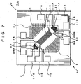
- a micro-flow sensor generally 1a , includes a Si board 2, a diaphragm 3, a micro-heater 4, a downstream thermopile 5, power source terminals 6A, 6B, first output terminals 7A, 7B, upstream thermopile 8 and second output terminals 9A, 9B.
- the micro-flow sensor 1a further includes a right temperature measuring resistor 21, third output terminals 12A, 12B, a left temperature measuring resistor 23 and fourth output terminals 14A, 14B.
- the right temperature measuring resistor 21 is arranged in a direction orthogonal to the flow direction (direction from P to Q) of fluid with respect to the micro-heater 4 and serves to detect the temperature of the fluid to produce a right temperature detected signal.
- the third output terminals 22A, 22B provide the right temperature detected. signal produced from the right temperature measuring resistor 21.
- the left temperature measuring resistor 23 is arranged in a direction orthogonal to the flow direction of fluid with respect to the micro-heater 4 and serves to detect the temperature of the fluid to produce a left temperature detected signal.
- the fourth output terminals 24A, 24B provide the left temperature detected signal produced from the left temperature measuring resistor 23.
- the micro-flow sensor 1 further includes resistors 15, 16 and output terminals 17A, 17B.
- the right temperature measuring resistor 21 and the left temperature measuring resistor 23 constitute a temperature sensor, and are made of Pt and others like the micro-heater 4.
- the right temperature measuring resistor 21 and left temperature measuring resistor 23 are arranged.
- the right temperature measuring resistor 21 detects the temperature of the fluid to supply the right temperature detected signal to the third output terminals 22A, 22B.
- the left temperature measuring resistor 23 detects the temperature of the fluid to the left temperature signal to supply the fourth output terminals 24A, 24B.
- the property of the fluid such as the thermal dispersion coefficient which is determined by thermal conduction, thermal dispersion, specific heat, etc. can be computed on the basis of the right temperature detected signal and the left temperature detected signal.
- the flow rate measuring apparatus 1a for measuring the flow rate using the micro-flow sensor includes a differential amplifier 33 for amplifying the difference signal between the second temperature detected signal (from the downstream thermopile 5 within the micro-flow sensor 1) and the first temperature detected signal (from the upstream thermopile 8 within the micro-flow sensor 1), and a bridge circuit 39 in which the right temperature measuring resistor 21 and left temperature measuring resistor 23 are opposite to two fixed resistors 38a and 38b having equal resistances and these resistors are bridge-connected.
- the flow rate measuring apparatus further includes a constant voltage source 37 for applying a constant voltage between the junction point of the right temperature measuring resistor 21 and fixed resistor 38b and the junction point of the left temperature measuring resistor 23 and the fixed resistor 38a; a differential amplifier 36 for differentially amplifying the potential between the junction point A of the right temperature measuring resistor 21 and the fixed resistor 38a and the junction point B of the left temperature measuring resistor 23 and the fixed resistor 38b; and a microcomputer 40.
- the microcomputer 40 includes a divider unit (or parameter selecting unit) 49, a flow rate computing unit 41 and a fluid property computing unit 43.
- the divider unit (or parameter selecting unit) 47 divides the amplified differential signal (between the second temperature detected signal from the downstream thermopile 5 and the first temperature detected signal from the upstream thermopile 8) by the amplified addition signal supplied from the differential amplifier 36, thereby providing a division signal.
- the flow rate computing unit 41 computes the accurate flow rate of the fluid on the basis of the division signal.
- the fluid property computing unit 43 computes the property of the fluid such as thermal conductivity, specific heat, viscosity, density, etc. on the basis of the accurate flow rate computed by the flow rate computing unit 41 and the amplified addition signal supplied from the differential amplifier 36.
- the flow rate of the fluid can be accurately measured irrespectively of the kind and composition of the fluid.
- the same effect as the flow rate measuring apparatus using the micro-flow sensor according to the first embodiment can be obtained.
- the present invention should not be limited to the micro-flow sensor 1, 1a, flow rate measuring apparatus and method using them.
- the thermopile was used as a temperature sensor.
- the temperature measuring resistor of Pt resistor was used as a temperature sensor.
- the temperature sensor should not be limited to these elements, but may be any temperature sensor such as a corrector, thermistor, etc. which are used usually.
- the thermal fluid sensor consisting of the right thermopile 11, left thermopile 13 and mciroheater 4 to detect the property of the fluid was formed integrally to the micro-flow sensor 1, 1a consisting of the downstream thermopile 5, upstream thermopile 8 and micro-heater 4 to measure the flow velocity (flow rate) of the fluid.
- this thermal fluid sensor consisting of the right thermopile 11, left thermopile 13 and mciroheater 4 may be provided separately from the micro-flow sensor 1, 1a.
- the property of the fluid can be computed by the fluid property computing unit 43 of the microcomputer 40 on the basis of the right temperature detected signal produced from the third output terminals 12A, 12B by the electromotive force from the right thermopile 11 and/or the left temperature detected signal produced from the fourth output terminals 14A, 14B by the electromotive force from the left thermopile. Further, the kind of the fluid can be inferred on the basis of the property of the fluid by the microcomputer 40.
- the amplified differential signal from the differential amplifier 33 may be corrected using a prescribed correction coefficient corresponding to the kind of the fluid inferred by the microcomputer 40, thereby computing the flow rate.
- a table on which the kinds of the fluid are linked with the correction coefficients is previously stored in an internal memory (ROM) of the microcomputer 40 or an external memory (preferably non-volatile) connected to the microcomputer 40.
- the amplified difference signal from the differential amplifier 33 is multiplied by the correction coefficient corresponding to the kind of the inferred fluid which is read from the internal memory or external memory, thereby realizing computation of the flow rate. This relaxes the burden in the processing of computing the flow rate.
- another table may be previously stored in an internal memory (ROM) of the microcomputer 40 or an external memory (preferably non-volatile) connected to the microcomputer 40.
- ROM internal memory
- an external memory preferably non-volatile
- Still another table may be previously stored in an internal memory (ROM) of the microcomputer 40 or an external memory (preferably non-volatile) connected to the microcomputer 40.
- ROM read-only memory
- the flow rate of the fluid computed by the flow rate computing unit 41 on the basis of the second temperature detected signal and the first temperature detected signal is linked with a reference value of the corresponding third temperature detected signal from the right thermopile 11 or the left thermopile 13.
- the fluid property computing unit 43 of the microcomputer 40 computes the property of the fluid on the basis of the ratio of the reference value of the third temperature detected signal, which is derived from the external memory using the flow rate computed by the flow rate computing unit 41 as an address pointer, to the third temperature detected signal actually acquired from the right thermopile 11 and the left thermopile 13.
- the above property of the fluid can be computed by multiplying the above ratio of the actual third temperature detected signal and its reference value by the output from the differential amplifier 33.
- the temperature sensors for detecting the property of the fluid were arranged on both right and lefts of the micro-heater 4.
- the temperature sensor may be arranged on one of both right and lefts to detect the temperature of the fluid, thereby computing the property of the fluid.
- the average value of the output signals from both temperature sensors is used to detect the property of the fluid.
- the output therefrom is used to detect the property of the fluid.
- the division by the divider unit 47 may be selectively carried out according to the value of the output from the differential amplifier 33 which results from amplifying the difference signal between the second temperature detected signal and the first temperature detected signal.
- the output signal values of the second temperature detected signal and the first temperature detected signal increase in proportion to the flow rate.
- they do not increase in proportion to the flow rate, but have a tendency of saturation.
- the difference signal amplified by the differential amplifier 33 may be dealt with as a flow rate signal as it is.
- the divider unit 49 divides the amplified difference signal from the differential amplifier 33 by the average value of the third temperature detected signals or one of them to exclude the influence of saturation of the temperature detected signal so that the divided value is used as the flow rate signal.
- the amplified difference signal between the second temperature detected signal and the first temperature detected signal which could not be used for the measurement of the flow rate in the region with the relatively high flow rate as described above, can be used for this purpose together with the average value of the third temperature detected signals from the left thermopile 11 and the right thermopile 13 or one of them.
- the range of measurement where the flow rate can be measured accurately can be improved by 100 - 1000 times as large as before. This permits various leakage states in e.g. gas meter to be detected by a single sensor.
- a heater heats an object fluid flowing through a flow path by a driving current externally supplied.
- a side temperature sensor arranged in an direction orthogonal to the flow direction of the object fluid with respect to the heater detects the thermal conductivity of the object fluid so that a temperature detected signal is produced. Therefore, the property of the fluid can be computed on the basis of the temperature detected signal.
- the thermal conductivity of the object fluid is detected by two side temperature sensors are arranged on both sides of the heater in a direction orthogonal to the flow direction of the object fluid. Therefore, even when there is a change in the flow of the object fluid in the flow path in a direction orthogonal to the flow direction, the property of the fluid can be accurately computed on the basis of the temperature detected signals from both side temperature sensors.
- the heater and the side temperature sensor are formed on the diaphragm.
- the thermal capacity of the heater and temperature sensor can be decreased to reduce power consumption.
- the side temperature sensor is a thermopile. Therefore, the temperature detected signal provides a small change in the characteristic which depends on a change in the temperature. This contributes to accurate measurement of the flow rate. Since the thermopile itself does not generate heat, correction is not required. Since the thermopile produces an output signal due to its own electromotive force, it does not consume the power.
- the side temperature sensor is a collector. Therefore, the high response speed and sensitivity to the temperature detected signal can be provided so that the flow rate can be measured at a high speed. Since the collector produces an output signal due to its own electromotive force, it does not consume the power.
- a fluid property computes the property of the object fluid on the basis of the temperature detected signal supplied from the side temperature sensor in the thermal fluid sensor.
- the fluid property can be used to correct the output from the flow rate sensor which varies according to the kind or composition of the object fluid, or to decide that the kind or composition of the object fluid flowing through the flow path has changed.
- a reference value storage means stores a plurality of kinds of reference values of the temperature detected signal supplied from the side temperature sensor within the thermal fluid sensor, the reference values corresponding to flow rates of the object fluid flowing through the flow path.
- the reference value inferring means infers a single reference value corresponding to the flow rate of the object fluid measured by the flow rate measuring means from the plurality of kinds of reference values stored in the reference value storage means.
- the temperature detected signal ratio computing means for computing a ratio of the reference value inferred by the reference value inferring means to the temperature detected signal supplied from the side temperature sensor. Therefore, the fluid property computing means can easily compute the property of the object fluid on the basis of the ratio computed by the temperature detected signal ratio computing means.
- the fluid property computing means multiplies the flow rate or its square root of the object fluid flowing through the flow path measured by the flow rate measuring means by the temperature detected signal supplied from the side temperature sensor in the thermal fluid sensor.
- the fluid property computing means can easily compute the property of the object fluid flowing through the flow path.
- the kind of the object fluid discriminated by the kind discriminating means is used to correct the output from the flow rate sensor and discriminate a change in the kind or the composition of the fluid flowing through the flow path.
- reference range data storage means stores data of a plurality of kinds of reference ranges of the temperature detected signal corresponding to the flow rates of the object fluid flowing through the flow path, the reference ranges being different according to the kinds of the object fluid and correlated with the kinds.
- the reference range data inferring means infers a single reference range data corresponding to the flow rate of the object fluid from data of the plurality of reference ranges stored in the reference range data storage means.
- the pertinent reference range determining means determines the reference range correlated with the object fluid to which the temperature detected signal belongs. On the basis of the reference range thus determined, the kind of the object fluid flowing through the flow path can be easily discriminated.
- the kind of the object fluid thus discriminated is used to correct the output from the flow rate sensor and discriminate a change in the kind or the composition of the fluid flowing through the flow path.
- the property of the object fluid is computed on the basis of the temperature detected signal supplied from the side temperature sensor in the thermal fluid sensor.
- the property of the object fluid thus computed is used to correct the output from the flow rate sensor which varies according to the kind and composition of the object fluid and to discriminate a change in the kind or the composition of the fluid flowing through the flow path.
- the kind of the object fluid is discriminated on the basis of the property of the object fluid.
- the kind of the fluid thus criminated can be used to correct the output from the flow rate sensor which varies according to the kind and composition of the object fluid.
- a single reference value corresponding to the flow rate of the object fluid measured in the flow rate measuring step is inferred from a plurality of kinds of reference values of the temperature detected signal supplied from the side temperature sensor within the thermal fluid sensor, the reference values corresponding to flow rates of the object fluid flowing through the flow path.
- a ratio of the reference value inferred by the reference value inferring means to the temperature detected signal supplied from the side temperature sensor is computed.
- the fluid property computing step the property of the object fluid can be easily computed on the basis of the ratio thus computed.
- the flow rate or its square root of the object fluid flowing through the flow path measured by the flow rate measuring means is multiplied by the temperature detected signal supplied from the side temperature sensor in the thermal fluid sensor, thereby easily acquiring the property of the object fluid.
- the flow rate of the object fluid flowing through the fluid path is measured; in the reference range data inferring step, a single reference range data corresponding to the flow rate of the object fluid is inferred from a group of data of a plurality of prescribed reference ranges of the temperature detected signal corresponding to the flow rates of the object fluid flowing through the flow path, the reference ranges being different according to the kinds of the object fluid and correlated with the kinds; in the pertinent reference range determining step, the reference range correlated with the object fluid to which the temperature detected signal belongs is determined.
- the kind of the fluid flowing through the flow path can be easily discriminated.
- the kind of the object fluid thus discriminated can be used to correct the output from the flow rate sensor which varies according to the kind or composition of the fluid and discriminate a change in the kind or the composition of the fluid flowing through the flow path.
- the flow rate of the fluid measured by the flow rate measuring means is corrected by the flow rate correcting means. Therefore, the flow rate of the object fluid can be measured accurately according to the kind or composition of the object fluid.
- the flow rate measuring means provides an output signal having a value corresponding to the measured flow rate of the object fluid flowing through the flow path, and the flow rate correcting means produces a flow rate detected signal when the output signal is divided by the temperature detected signal. Therefore, the flow rate measured by the flow rate measuring means can be easily corrected.
- the flow rate of the object fluid flowing through the flow path is measured; whether the flow rate of the fluid measured by the flow rate measuring means is in a high flow rate state or a low flow rate is decided; an output signal from the flow rate measuring means is produced as a flow rate detected signal as it is if the flow rate is decided to be in the low flow rate state, and another output signal when the output signal from the flow rate measuring means is divided by the temperature detected signal from the side temperature sensor is produced if the flow rate is decided to be in the high flow rate state.
- the flow rate of the fluid can be measured accurately in a wider range.
- a single parameter is selected from the plurality of kinds of parameters stored in the parameter storage means on the basis of the property of the object fluid computed by the fluid property computing means, and the flow rate converted from the output signal from the flow rate measuring means using the single parameter selected by the selecting means is taken as the measured value of the flow rate of the object fluid flowing through the flow path. Therefore, the flow rate of the fluid can be measured accurately according to the kind or composition which defines the property of the object fluid.
- the flow rate of the fluid measured in the flow rate measuring step is corrected in the flow rate correcting step. Therefore, the flow rate of the object fluid can be measured accurately according to the kind or composition of the object fluid.
- the flow rate measuring step provides an output signal having a value corresponding to the measured flow rate of the object fluid flowing through the flow path, and the flow rate correcting step produces a flow rate detected signal when the output signal is divided by the temperature detected signal. Therefore, the flow rate measured by the flow rate measuring step can be easily corrected.
- the flow rate of the object fluid flowing through the flow path is measured; whether the flow rate of the fluid measured in the flow rate measuring step is in a high flow rate state or a low flow rate is decided; an output signal acquired in the flow rate measuring step is produced as a flow rate detected signal as it is if the flow rate is decided to be in the low flow rate state, and another output signal when the output signal from the flow rate measuring step is divided by the temperature detected signal from the side temperature sensor is produced if the flow rate is decided to be in the high flow rate state.
- the flow rate of the fluid can be measured accurately in a wider range.
- a single parameter is selected from the plurality of kinds of prescribed parameters on the basis of the property of the object fluid computed by the fluid property computing step, and the flow rate converted from the output signal from the flow rate measuring step using the single parameter selected in the selecting step is taken as the measured value of the flow rate of the object fluid flowing through the flow path. Therefore, the flow rate of the fluid can be measured accurately according to the kind or composition which defines the property of the object fluid.
- a heater supported by a supporting board heats an object fluid flowing through a flow path by a driving current externally supplied.
- the upstream temperature sensor arranged upstream of the object fluid with respect to the heater detects the temperature of the object fluid so that a first temperature detected signal is produced.
- the downstream temperature sensor arranged downstream of the object fluid with respect to the heater also detects the temperature of the object fluid so that a second temperature detected signal is produced.
- the side temperature sensor arranged in a direction orthogonal to the flow direction of the object fluid with respect to the heater to detect the temperature of the object fluid so that a third temperature detected signal is produced. Therefore, the property of the fluid can be computed on the basis of the third temperature detected signal.
- two side temperature sensors are arranged on both sides of the heater in a direction orthogonal to the flow direction of the object fluid. Therefore, even when there is a variation in the flow of the object fluid in the flow path in a direction orthogonal to the flow direction, the property of the fluid can be accurately computed on the basis of the third temperature detected signals from both side temperature sensors.
- the heater, the upstream temperature sensor, the downstream temperature sensor and the side temperature sensor are formed on the diaphragm.
- the thermal capacity of the heater and temperature sensors can be decreased to reduce power consumption.
- the upstream temperature sensor and the downstream temperature sensors are a thermopile, respectively. Therefore, the difference signal between the first and the second temperature detected signal provides a small change in the characteristic which depends on a change in the temperature. This contributes to accurate measurement of the flow rate. Since the thermopile itself does not generate heat, correction is not required. Since the thermopile produces an output signal due to its own electromotive force, it does not consume the power.
- the upstream sensor and the downstream sensors are a collector, respectively. Therefore, the high response speed and sensitivity to the temperature detected signal can be provide so that the flow rate can be measured at a high speed. Since the collector produces an output signal due to its own electromotive force, it does not consume the power.
- thermopile since the side temperature sensor is a thermopile,
- the third temperature detected signal provides a small change in the characteristic which depends on a change in the temperature. This contributes to accurate measurement of the flow rate. Since the thermopile itself does not generate heat, correction is not required. Since the thermopile produces an output signal due to its own electromotive force, it does not consume the power.
- the side temperature sensor is a collector, respectively. Therefore, the high response speed and sensitivity to the third temperature detected signal can be provide so that the flow rate can be measured at a high speed. Since the collector produces an output signal due to its own electromotive force, it does not consume the power.
- the flow rate measuring means measures a flow rate of the object fluid on the basis of a difference signal between the first temperature detected signal supplied from the upstream temperature sensor and the second temperature detected signal supplied from the downstream temperature sensor; reference value storage means stores a plurality of kinds of reference values of the third temperature detected signal supplied from the side temperature sensor within the flow sensor, the reference values corresponding to flow rates of the object fluid flowing through the flow path; reference value inferring means infers a single reference value corresponding to the flow rate of the object fluid measured by the flow rate measuring means from the plurality of kinds of reference values stored in the reference value storage means; and temperature detected signal ratio computing means for computing a ratio of the reference value inferred by the reference value inferring means to the third temperature detected signal supplied from the side temperature sensor.
- the fluid property computing means can easily compute the property of the object fluid on the basis of the ratio computed by the temperature detected signal ratio computing means.
- the property of the object fluid thus discriminated can be used to correct the output from the flow rate sensor which varies according to the kind or composition of the fluid and discriminate a change in the kind or the composition of the fluid flowing through the flow path.
- flow rate measuring means measures a flow rate of the object fluid on the basis of a difference signal between the first temperature detected signal supplied from the upstream temperature sensor and the second temperature detected signal supplied from the downstream temperature sensor; and fluid property computing means multiplies the flow rate or its square root of the object fluid flowing through the flow path measured by the flow rate measuring means by the third temperature detected signal supplied from the side temperature sensor in the flow sensor, thereby acquiring the property of the object fluid.
- the property of the object fluid thus computed can be used to correct the output from the flow rate sensor which varies according to the kind or composition of the fluid and discriminate a change in the kind or the composition of the fluid flowing through the flow path.
- fluid kind discriminating means discriminates the kind of the object fluid on the basis of the property of the object fluid.
- the kind of the object fluid thus discriminated can be used to correct the output from the flow rate sensor which varies according to the kind or composition of the fluid.
- the flow rate measuring means measures a flow rate of the object fluid on the basis of a difference signal between the first temperature detected signal supplied from the upstream temperature sensor and the second temperature detected signal supplied from the downstream temperature sensor; and reference range data inferring means infers a single reference range data corresponding to the flow rate of the object fluid from data of the plurality of reference ranges of the third temperature detected signal corresponding to flow rates of the object fluid flowing through the flow path, the reference ranges being different according to the kinds of the object fluid and correlated with the kinds; and the pertinent reference range determining means determines the reference range correlated with the object fluid to which the third temperature detected signal belongs.
- the kind of the object fluid can be easily discriminated on the basis of the reference range thus determined.
- the kind of the object fluid thus discriminated can be used to correct the output from the flow rate sensor which varies according to the kind or composition of the fluid and discriminate a change in the kind or the composition of the fluid flowing through the flow path.
- a flow rate of the object fluid is measured on the basis of a difference signal between the first temperature detected signal supplied from the upstream temperature sensor and the second temperature detected signal supplied from the downstream temperature sensor; in the reference value storage step, a plurality of kinds of reference values of the third temperature detected signal supplied from the side temperature sensor within the flow sensor are stored, the reference values corresponding to flow rates of the object fluid flowing through the flow path; in the reference value inferring step, a single reference value corresponding to the flow rate of the object fluid measured by the flow rate measuring means is inferred from the plurality of kinds of reference values stored in the reference value storage means; and in the temperature detected signal ratio computing step, a ratio of the reference value inferred in the reference value inferring step to the third temperature detected signal supplied from the side temperature sensor is computed; and in the fluid property computing step, the property of the object fluid is computed on the basis of the ratio thus computed. In this case, the property of the object fluid thus computed can be used to correct
- a flow rate of the object fluid is computed on the basis of a difference signal between the first temperature detected signal supplied from the upstream temperature sensor and the second temperature detected signal supplied from the downstream temperature sensor; and in the fluid property computing step, the flow rate or its square root of the object fluid flowing through the flow path measured by the flow rate measuring means is multiplied by the temperature detected signal supplied from the side temperature sensor in the flow sensor, thereby acquiring the property of the object fluid.
- the property of the object fluid thus acquired can be used to correct the output from the flow rate sensor which varies according to the kind or composition of the fluid and discriminate a change in the kind or the composition of the fluid flowing through the flow path.
- the kind of the object fluid is discriminated on the basis of the property of the object fluid.
- the kind of the object fluid thus computed can be used to correct the output from the flow rate sensor which varies according to the kind or composition of the object fluid.
- a flow rate of the object fluid is measured on the basis of a difference signal between the first temperature detected signal supplied from the upstream temperature sensor and the second temperature detected signal supplied from the downstream temperature sensor; and in the reference range data inferring step, a single reference range data corresponding to the flow rate of the object fluid is inferred from data of a plurality kinds of reference ranges the third temperature detected signal corresponding flow rates of the object fluid flowing through the flow path, the reference ranges being different according to the kinds of the object fluid and correlated with the kinds; and in the pertinent reference range determining step, the reference range correlated with the object fluid to which the third temperature detected signal belongs is determined.
- the kind of the object fluid can be easily discriminated on the basis of the reference range thus determined.
- the kind of the object fluid thus discriminated can be used to correct the output from the flow rate sensor which varies according to the kind or composition of the fluid and discriminate a change in the kind or the composition of the fluid flowing through the flow path.
- the flow rate computing means computes a flow rate of the object fluid on the basis of a difference signal between the first temperature detected signal supplied from the upstream temperature sensor and the second temperature detected signal supplied from the downstream temperature sensor; and the fluid property computing means computes the property of the object fluid on the basis of the third temperature detected signal supplied from the side temperature sensor with the flow sensor; and flow rate correcting means corrects the flow rate of the object fluid computed by the flow rate computing means on the basis of the property of the object fluid computed by the fluid property computing means. This permits the flow rate to be measured accurately even when the kind or composition of the fluid is changed.
- the flow rate correcting means produces a flow rate detected signal when the difference signal is divided by the third temperature detected signal. This permits the flow rate measured by the flow rate measuring means to be easily corrected.
- the flow rate computing means computes a flow rate of the object fluid on the basis of a difference signal between the first temperature detected signal supplied from the upstream temperature sensor and the second temperature detected signal supplied from the downstream temperature sensor; and deciding means decides whether the flow rate of the fluid measured by the flow rate measuring means is in a high flow rate state or a low flow rate; and flow rate outputting means outputs an output signal from the flow rate measuring means as a flow rate detected signal as it is if the flow rate is decided to be in the low flow rate state, and another output signal when the output signal from the flow rate measuring means is divided by the third temperature detected signal from the side temperature sensor if the flow rate is decided to be in the high flow rate state. In this way, the flow rate of the fluid can be measured accurately in a wider range.
- a single parameter is selected from the plurality of kinds of parameters stored in the parameter storage means on the basis of the property of the object fluid computed by the fluid property computing means, and the flow rate converted from the output signal from the flow rate computing means using the single parameter selected by the selecting means is taken as the measured value of the flow rate of the object fluid flowing through the flow path. Therefore, the flow rate of the fluid can be measured accurately according to the kind or composition which defines the property of the object fluid.
- a flow rate of the object fluid is computed on the basis of a difference signal between the first temperature detected signal supplied from the upstream temperature sensor and the second temperature detected signal supplied from the downstream temperature sensor; and in the fluid property computing step, the property of the object fluid is computed on the basis of the third temperature detected signal supplied from the side temperature sensor with the flow sensor; and in the flow rate correcting step, the flow rate of the object fluid computed in the flow rate computing step is corrected on the basis of the property of the object fluid computed in the fluid property computing step. This permits the flow rate to be measured accurately even when the kind or composition of the fluid is changed.
- a flow rate detected signal when the difference signal is divided by the third temperature detected signal is produced. This permits the flow rate measured by the flow rate measuring step to be easily corrected.
- the flow rate of the object fluid is computed on the basis of a difference signal between the first temperature detected signal supplied from the upstream temperature sensor and the second temperature detected signal supplied from the downstream temperature sensor; and in the deciding step, it is decided whether the flow rate of the fluid measured in the flow rate measuring step is in a high flow rate state or a low flow rate; and in the flow rate outputting step, outputted are an output signal acquired in the flow rate measuring step as a flow rate detected signal as it is if the flow rate is decided to be in the low flow rate state, and another output signal when the output signal from the flow rate measuring step is divided by the third temperature detected signal from the side temperature sensor if the flow rate is decided to be in the high flow rate state. In this way, the flow rate of the fluid can be measured accurately in a wider range.
- a single parameter is selected from the plurality of kinds of parameters stored in the parameter storage step on the basis of the property of the object fluid computed by the fluid property computing step, and the flow rate converted from the output signal from the flow rate computing step using the single parameter selected by the selecting step is taken as the measured value of the flow rate of the object fluid flowing through the flow path. Therefore, the flow rate of the fluid can be measured accurately according to the kind or composition which defines the property of the object fluid.
Landscapes
- Physics & Mathematics (AREA)
- General Physics & Mathematics (AREA)
- Fluid Mechanics (AREA)
- Chemical & Material Sciences (AREA)
- Health & Medical Sciences (AREA)
- Life Sciences & Earth Sciences (AREA)
- Analytical Chemistry (AREA)
- Biochemistry (AREA)
- General Health & Medical Sciences (AREA)
- Immunology (AREA)
- Pathology (AREA)
- Electrochemistry (AREA)
- Chemical Kinetics & Catalysis (AREA)
- Measuring Volume Flow (AREA)
- Investigating Or Analyzing Materials Using Thermal Means (AREA)
Abstract
Description
wherein it is determined that the object fluid correlated with the reference range thus determined is the object fluid flowing through the flow path.
wherein it is determined that the object fluid correlated with the reference range thus determined is the object fluid flowing through the flow path.
wherein the flow rate converted from the output signal from the flow rate measuring means using the single parameter selected in the selecting step is taken as the measured value of the flow rate of the object fluid flowing through the flow path.
wherein the fluid property computing means computes the property of the object fluid on the basis of the ratio computed by the temperature detected signal ratio computing means.
wherein it is determined that the object fluid correlated with the reference range thus determined is the object fluid flowing through the flow path.
wherein the fluid property computing means computes the property of the object fluid on the basis of the ratio computed by the temperature detected signal ratio computing means.
wherein it is determined that the object fluid correlated with the reference range thus determined is the object fluid flowing through the flow path.
the flow rate converted from the output signal from the flow rate computing step using the single parameter selected in the selecting step is taken as the measured value of the flow rate of the object fluid flowing through the flow path.
Claims (46)
- A thermal fluid sensor comprising:a heater for heating an object fluid for measurement flowing through a flow path by a driving current externally supplied;a side temperature sensor arranged in a direction orthogonal to the flow direction of the object fluid with respect to the heater to detect the temperature of the object fluid so that a temperature detected signal is produced; anda supporting board for supporting the heater and the side temperature sensor.
- A thermal fluid sensor according to claim 1, wherein two side temperature sensors are arranged on both sides of the heater in a direction orthogonal to the flow direction of the object fluid.
- A thermal fluid sensor according to claim 1, wherein the supporting board has a diaphragm whose periphery is fixed, and the heater and the side temperature sensor are formed on the diaphragm.
- A thermal fluid sensor according to claim 1, wherein the side temperature sensor is a thermopile.
- A thermal fluid sensor according to claim 1, wherein the side temperature sensor is a collector.
- A fluid discriminating apparatus for discriminating the kind of the object fluid using the thermal fluid sensor set force in claim 1, comprising:fluid property computing means for computing the property of the object fluid on the basis of the temperature detected signal supplied from the side temperature sensor in the thermal fluid sensor.
- A fluid discriminating apparatus according to claim 6, comprising:flow rate measuring means for measuring a flow rate of the object fluid flowing through the flow path;reference value storage means for storing a plurality of kinds of reference values of the temperature detected signal supplied from the side temperature sensor within the thermal fluid sensor, the reference values corresponding to flow rates of the object fluid flowing through the flow path;reference value inferring means for inferring a single reference value corresponding to the flow rate of the object fluid measured by the flow rate measuring means from the plurality of kinds of reference values stored in the reference value storage means; andtemperature detected signal ratio computing means for computing a ratio of the reference value inferred by the reference value inferring means to the temperature detected signal supplied from the side temperature sensor,
wherein the fluid property computing means computes the property of the object fluid on the basis of the ratio computed by the temperature detected signal ratio computing means. - A fluid discriminating apparatus according to claim 6, wherein the fluid property computing means multiplies the flow rate or its square root of the object fluid flowing through the flow path measured by the flow rate measuring means by the temperature detected signal supplied from the side temperature sensor in the thermal fluid sensor, thereby acquiring the property of the object fluid.
- A fluid discriminating apparatus according to claim 6, further comprising: fluid kind discriminating means for discriminating the kind of the object fluid on the basis of the property of the object fluid.
- A fluid discriminating apparatus for discriminating the kind of the object fluid using the thermal fluid sensor set forth in claim 1, comprising:flow rate measuring means for measuring the flow rate of the object fluid flowing through the fluid path;reference range data storage means for storing data of a plurality of kinds of reference ranges of the temperature detected signal corresponding to the flow rates of the object fluid flowing through the flow path, the reference ranges being different according to the kinds of the object fluid and correlated with the kinds;reference range data inferring means for inferring a single reference range data corresponding to the flow rate of the object fluid from data of the plurality of reference ranges stored in the reference range data storage means;pertinent reference range determining means for determining the reference range correlated with the object fluid to which the temperature detected signal belongs,
wherein it is determined that the object fluid correlated with the reference range thus determined is the object fluid flowing through the flow path. - A fluid discriminating method of discriminating the object fluid using the thermal fluid sensor set forth in claim 1, comprising:fluid-property computing step of computing the property of the object fluid on the basis of the temperature detected signal supplied from the side temperature sensor in the thermal fluid sensor.
- A fluid discriminating method according to claim 11, further comprising: fluid kind discriminating step of discriminating the kind of the object fluid on the basis of the property of the object fluid.
- A fluid discriminating method according to claim 11 comprising:flow rate measuring step of measuring a flow rate of the I object fluid flowing through the flow path;reference value inferring step of inferring a single reference value corresponding to the flow rate of the object fluid measured in the flow rate measuring step from a plurality of kinds of reference values of the temperature detected signal supplied from the side temperature sensor within the thermal fluid sensor, the reference values corresponding to flow rates of the object fluid flowing through the flow path;temperature detected signal ratio computing step of computing a ratio of the reference value inferred by the reference value inferring means to the temperature detected signal supplied from the side temperature sensor,
wherein the fluid property computing step computes the property of the object fluid on the basis of the ratio computed in the temperature detected signal ratio computing step. - A fluid discriminating method according to claim 11, wherein the fluid property computing step multiplies the flow rate or its square root of the object fluid flowing through the flow path measured by the flow rate measuring means by the temperature detected signal supplied from the side temperature sensor in the thermal fluid sensor, thereby acquiring the property of the object fluid.
- A fluid discriminating method for discriminating the kind of the object fluid using the thermal fluid sensor set forth in claim 1, comprising:flow rate measuring step of measuring the flow rate of the object fluid flowing through the fluid path;reference range data inferring step of inferring a single reference range data corresponding to the flow rate of the object fluid from a group of data of a plurality of prescribed reference ranges of the temperature detected signal corresponding to the flow rates of the object fluid flowing through the flow path, the reference ranges being different according to the kinds of the object fluid and correlated with the kinds;pertinent reference range determining step of determining the reference range correlated with the object fluid to which the temperature detected signal belongs,
wherein it is determined that the object fluid correlated with the reference range thus determined is the object fluid flowing through the flow path. - A flow rate measuring apparatus for measuring the flow rate of the object fluid flowing through the flow path using the thermal fluid sensor set forth in claim 1, comprising:flow rate measuring means for measuring the flow rate of the object fluid flowing through the flow path; andflow rate correcting means for correcting the flow rate of the fluid measured by the flow rate measuring means.
- A flow rate measuring apparatus according to claim 16, wherein the flow rate measuring means provides an output signal having a value corresponding to the measured flow rate of the object fluid flowing through the flow path, and the flow rate correcting means produces a flow rate detected signal when the output signal is divided by the temperature detected signal, thereby correcting the flow rate measured by the flow rate measuring means.
- A flow rate measuring apparatus for measuring the flow rate of the object fluid flowing through the flow path using the thermal fluid sensor set forth in claim 1, comprising:flow rate measuring means for measuring the flow rate of the object fluid flowing through the flow path;deciding means for deciding whether the flow rate of the fluid measured by the flow rate measuring means is in a high flow rate state or a low flow rate;flow rate outputting means for outputting an output signal from the flow rate measuring means as a flow rate detected signal as it is if the flow rate is decided to be in the low flow rate state, and another output signal when the output signal from the flow rate measuring means is divided by the temperature detected signal from the side temperature sensor if the flow rate is decided to be in the high flow rate state.
- A flow rate measuring apparatus for measuring the flow rate of the object fluid flowing through the flow path using the thermal fluid sensor set forth in claim 1,flow rate measuring means for measuring the flow rate of the fluid flowing through the flow path and producing an output signal having a value corresponding to the flow rate thus measured;fluid property computing means for computing the property of the object fluid on the basis of the temperature detected signal supplied from the side temperature sensor in the thermal fluid sensor;parameter storage means storing a plurality of kinds of parameters each for converting the output signal from the flow rate measuring means into a flow rate; andselecting means for selecting a single parameter of the plurality of kinds of parameters stored in the parameter storage means on the basis of the property of the object fluid computed by the fluid property computing means, whereinthe flow rate converted from the output signal from the flow rate measuring means using the single parameter selected by the selecting means is taken as the measured value of the flow rate of the object fluid flowing through the flow path.
- A flow rate measuring method for measuring the flow rate of the object fluid flowing through the flow path using the thermal fluid sensor set forth in claim 1, comprising:flow rate measuring step of measuring the flow rate of the object fluid flowing through the flow path; andflow rate correcting step of correcting the flow rate of the fluid measured by the flow rate measuring means.
- A flow rate measuring method according to claim 20, wherein the flow rate measuring step provides an output signal having a value corresponding to the measured flow rate of the object fluid flowing through the flow path, and the flow rate correcting step produces a flow rate detected signal when the output signal is divided by the temperature detected signal, thereby correcting the flow rate measured by the flow rate measuring step.
- A flow rate measuring method for measuring the flow rate of the object fluid flowing through the flow path using the thermal fluid sensor set forth in claim 1, comprising:flow rate measuring step of measuring the flow rate of the object fluid flowing through the flow path;deciding step of deciding whether the flow rate of the fluid measured by the flow rate measuring means is in a high flow rate state or a low flow rate;flow rate outputting step of outputting an output signal acquired in the flow rate measuring step as a flow rate detected signal as it is if the flow rate is decided to be in the low flow rate state, and another output signal when the output signal acquired in the flow rate measuring step is divided by the temperature detected signal from the side temperature sensor if the flow rate is decided to be in the high flow rate state.
- A flow rate measuring method for measuring the flow rate of the object fluid flowing through the flow path using the thermal fluid sensor set forth in claim 1,flow rate measuring step of measuring the flow rate of the fluid flowing through the flow path and producing an output signal having a value corresponding to the flow rate thus measured;fluid property computing step of computing the property of the object fluid on the basis of the temperature detected signal supplied from the side temperature sensor in the thermal fluid sensor;selecting means for selecting a single parameter of the plurality of kinds of prescribed parameters on the basis of the property of the object fluid computed in the fluid property computing step, the plurality of kinds of parameters each for converting the output signal from the flow rate measuring means into a flow rate,
wherein the flow rate converted from the output signal from the flow rate measuring means using the single parameter selected in the selecting step is taken as the measured value of the flow rate of the object fluid flowing through the flow path. - A flow sensor comprising:a heater for heating an object fluid for measurement flowing through a flow path by a driving current externally supplied;an upstream temperature sensor arranged upstream of the object fluid with respect to the heater to detect the temperature of the object fluid so that a first temperature detected signal is produced;a downstream temperature sensor arranged downstream of the object fluid with respect to the heater to detect the temperature of the object fluid so that a second temperature detected signal is produced;a side temperature sensor arranged in a direction orthogonal to the flow direction of the object fluid with respect to the heater to detect the temperature of the object fluid so that a third temperature detected signal is produced; anda supporting board for supporting the heater, the upstream sensor, the downstream sensor and the side temperature sensor.
- A flow sensor according to claim 24, wherein two side temperature sensors are arranged on both sides of the heater in a direction orthogonal to the flow direction of the object fluid.
- A flow sensor according to claim 24, wherein the supporting board has a diaphragm whose periphery is fixed, and the heater, the upstream temperature sensor, the downstream temperature sensor and the side temperature sensor are formed on the diaphragm.
- A flow sensor according to claim 24, wherein the upstream sensor and the downstream temperature sensors are a thermopile, respectively.
- A flow sensor according to claim 24, wherein the upstream temperature sensor and the downstream temperature sensors are a collector.
- A flow sensor according to claim 24, wherein the side temperature sensor is a thermopile.
- A flow sensor according to claim 24, wherein the side temperature sensor is a collector.
- A fluid discriminating apparatus for discriminating the kind of the object fluid using the thermal fluid sensor set force in claim 24,flow rate measuring means for measuring a flow rate of the object fluid on the basis of a difference signal between the first temperature detected signal supplied from the upstream temperature sensor and the second temperature detected signal supplied from the downstream temperature sensor;reference value storage means for storing a plurality of kinds of reference values of the third temperature detected signal supplied from the side temperature sensor within the flow sensor, the reference values corresponding to flow rates of the object fluid flowing through the flow path;reference value inferring means for inferring a single reference value corresponding to the flow rate of the object fluid measured by the flow rate measuring means from the plurality of kinds of reference values stored in the reference value storage means; andtemperature detected signal ratio computing means for computing a ratio of the reference value inferred by the reference value inferring means to the third temperature detected signal supplied from the side temperature sensor,
wherein the fluid property computing means computes the property of the object fluid on the basis of the ratio computed by the temperature detected signal ratio computing means. - A fluid discriminating apparatus according to claim 24,flow rate measuring means for measuring a flow rate of the object fluid on the basis of a difference signal between the first temperature detected signal supplied from the upstream temperature sensor and the second temperature detected signal supplied from the downstream temperature sensor; andfluid property computing means for multiplying the flow rate or its square root of the object fluid flowing through the flow path measured by the flow rate measuring means by the temperature detected signal supplied from the side temperature sensor in the flow sensor, thereby acquiring the property of the object fluid.
- A fluid discriminating apparatus according to claim 31, further comprising: fluid kind discriminating means for discriminating the kind of the object fluid on the basis of the property of the object fluid.
- A fluid discriminating apparatus for discriminating the kind of the object fluid using the flow sensor set forth in claim 24, comprising:flow rate measuring means for measuring a flow rate of the object fluid on the basis of a difference signal between the first temperature detected signal supplied from the upstream temperature sensor and the second temperature detected signal supplied from the downstream temperature sensor; andreference range data storage means for storing data of a plurality of kinds of reference ranges of the third temperature detected signal corresponding flow rates of the object fluid flowing through the flow path, the reference ranges being different according to the kinds of the object fluid and correlated with the kinds;reference range data inferring means for inferring a single reference range data corresponding to the flow rate of the object fluid from data of the plurality of reference ranges stored in the reference range data storage means;pertinent reference range determining means for determining the reference range correlated with the object fluid to which the third temperature detected signal belongs,
wherein it is determined that the object fluid correlated with the reference range thus determined is the object fluid flowing through the flow path. - A fluid discriminating method for discriminating the kind of the object fluid using the flow sensor set force in claim 24,flow rate measuring step of measuring a flow rate of the object fluid on the basis of a difference signal between the first temperature detected signal supplied from the upstream temperature sensor and the second temperature detected signal supplied from the downstream temperature sensor;reference value storage step of storing a plurality of kinds of reference values of the third temperature detected signal supplied from the side temperature sensor within the flow sensor, the reference values corresponding to flow rates of the object fluid flowing through the flow path;reference value inferring step of inferring a single reference value corresponding to the flow rate of the object fluid measured by the flow rate measuring means from the plurality of kinds of reference values stored in the reference value storage means; andtemperature detected signal ratio computing step of computing a ratio of the reference value inferred by the reference value inferring means to the third temperature detected signal supplied from the side temperature sensor,
wherein the fluid property computing means computes the property of the object fluid on the basis of the ratio computed by the temperature detected signal ratio computing means. - A fluid discriminating method for discriminating the kind of the object fluid using the flow sensor set force in claim 24,flow rate measuring step for computing a flow rate of the object fluid on the basis of a difference signal between the first temperature detected signal supplied from the upstream temperature sensor and the second temperature detected signal supplied from the downstream temperature sensor; andfluid property computing step of multiplying the flow rate or its square root of the object fluid flowing through the flow path measured by the flow rate measuring means by the temperature detected signal supplied from the side temperature sensor in the flow sensor, thereby acquiring the property of the object fluid.
- A fluid discriminating method according to claim 35, further comprising: fluid kind discriminating step of discriminating the kind of the object fluid on the basis of the property of the object fluid.
- A fluid discriminating method for discriminating the kind of the object fluid using the flow sensor set forth in claim 24, comprising:flow rate measuring step of measuring a flow rate of the object fluid on the basis of a difference signal between the first temperature detected signal supplied from the upstream temperature sensor and the second temperature detected signal supplied from the downstream temperature sensor; andreference range data inferring step of inferring a single reference range data corresponding to the flow rate of the object fluid from data of a plurality kinds of reference ranges the third temperature detected signal corresponding flow rates of the object fluid flowing through the flow path, the reference ranges being different according to the kinds of the object fluid and correlated with the kinds;pertinent reference range determining step of determining the reference range correlated with the object fluid to which the third temperature detected signal belongs,
wherein it is determined that the object fluid correlated with the reference range thus determined is the object fluid flowing through the flow path. - A flow rate measuring apparatus for measuring the flow rate of the object fluid flowing through the flow path using the flow sensor set forth in claim 24, comprising:flow rate computing means computing a flow rate of the object fluid on the basis of a difference signal between the first temperature detected signal supplied from the upstream temperature sensor and the second temperature detected signal supplied from the downstream temperature sensor; andfluid property computing means for computing the property of the object fluid on the basis of the third temperature detected signal supplied from the side temperature sensor with the flow sensor; andflow rate correcting means for correcting the flow rate of the object fluid computed by the flow rate computing means on the basis of the property of the object fluid computed by the fluid property computing means.
- A flow rate measuring apparatus according to claim 39, wherein the flow rate correcting means produces a flow rate detected signal when the difference signal is divided by the third temperature detected signal, thereby correcting the flow rate measured by the flow rate measuring means.
- A flow rate measuring apparatus for measuring the flow rate of the object fluid flowing through the flow path using the flow sensor set forth in claim 24, comprising:flow rate computing means for computing a flow rate of the object fluid on the basis of a difference signal between the first temperature detected signal supplied from the upstream temperature sensor and the second temperature detected signal supplied from the downstream temperature sensor; anddeciding means for deciding whether the flow rate of the fluid measured by the flow rate measuring means is in a high flow rate state or a low flow rate;flow rate outputting means for outputting an output signal from the flow rate measuring means as a flow rate detected signal as it is if the flow rate is decided to be in the low flow rate state, and another output signal when the output signal from the flow rate measuring means is divided by the third temperature detected signal from the side temperature sensor if the flow rate is decided to be in the high flow rate state.
- A flow rate measuring apparatus for measuring the flow rate of the object fluid flowing through the flow path using the flow sensor set forth in claim 24, comprising:flow rate computing means for computing a flow rate of the object fluid on the basis of a difference signal between the first temperature detected signal supplied from the upstream temperature sensor and the second temperature detected signal supplied from the downstream temperature sensor and producing an output signal having a value corresponding to the flow rate thus computed;fluid property computing means for computing the property of the object fluid on the basis of the third temperature detected signal supplied from the side temperature sensor in the flow sensor;parameter storage means storing a plurality of kinds of parameters each for converting the output signal from the flow rate computing means into a flow rate; andselecting means for selecting a single parameter of the plurality of kinds of parameters stored in the parameter storage means on the basis of the property of the object fluid computed by the fluid property computing means, whereinthe flow rate converted from the output signal from the flow rate measuring means using the single parameter selected by the selecting means is taken as the measured value of the flow rate of the object fluid flowing through the flow path.
- A flow rate measuring method for measuring the flow rate of the object fluid flowing through the flow path using the flow sensor set forth in claim 24, comprising:flow rate computing step of computing a flow rate of the object fluid on the basis of a difference signal between the first temperature detected signal supplied from the upstream temperature sensor and the second temperature detected signal supplied from the downstream temperature sensor; andfluid property computing step of computing the property of the object fluid on the basis of the third temperature detected signal supplied from the side temperature sensor within the flow sensor;flow rate correcting step of correcting the flow rate of the object fluid computed by the flow rate computing means on the basis of the property of the object fluid computed in the fluid property computing step.
- A flow rate measuring method according to claim 43, wherein the flow rate computing step acquires the signal having a value corresponding to the computed flow rate of the object fluid and the flow rate correcting step produces a flow rate detected signal when the difference signal is divided by the third temperature detected signal.
- A flow rate measuring method for measuring the flow rate of the object fluid flowing through the flow path using the flow sensor set forth in claim 24, comprising:flow rate computing step for computing a flow rate of the object fluid on the basis of a difference signal between the first temperature detected signal supplied from the upstream temperature sensor and the second temperature detected signal supplied from the downstream temperature sensor, thereby acquiring a signal having the value corresponding to the computed flow rate; anddeciding step for deciding whether the flow rate of the fluid acquired in the flow rate measuring step is in a high flow rate state or a low flow rate;flow rate outputting step for outputting an output signal acquired in the flow rate computing step as a flow rate detected signal as it is if the flow rate is decided to be in the low flow rate state, and another output signal when the output signal acquired in the flow rate computing step is divided by the third temperature detected signal from the side temperature sensor if the flow rate is decided to be in the high flow rate state.
- A flow rate measuring method for measuring the flow rate of the object fluid flowing through the flow path using the flow sensor set forth in claim 24,flow rate computing step of computing a flow rate of the object fluid on the basis of a difference signal between the first temperature detected signal supplied from the upstream temperature sensor and the second temperature detected signal supplied from the downstream temperature sensor and producing an output signal having a value corresponding to the flow rate thus computed;fluid property computing step of computing the property of the object fluid on the basis of the third temperature detected signal supplied from the side temperature sensor in the flow sensor;parameter storage step of storing a plurality of kinds of parameters each for converting the output signal acquired in the flow rate computing step into a flow rate; andselecting step of selecting a single parameter of the plurality of kinds of parameters on the basis of the property of the object fluid computed in the fluid property computing step, wherein
the flow rate converted from the output signal from the flow rate computing step using the single parameter selected in the selecting step is taken as the measured value of the flow rate of the object fluid flowing through the flow path.
Applications Claiming Priority (5)
| Application Number | Priority Date | Filing Date | Title |
|---|---|---|---|
| JP12061499 | 1999-04-27 | ||
| JP12061499 | 1999-04-27 | ||
| JP2000094437A JP4050857B2 (en) | 1999-04-27 | 2000-03-30 | Fluid discrimination device and flow rate measuring device |
| JP2000094437 | 2000-03-30 | ||
| PCT/JP2000/002688 WO2000065315A1 (en) | 1999-04-27 | 2000-04-25 | Thermal flow sensor, method and apparatus for identifying fluid, flow sensor, and method and apparatus for flow measurement |
Publications (2)
| Publication Number | Publication Date |
|---|---|
| EP1094306A1 true EP1094306A1 (en) | 2001-04-25 |
| EP1094306A4 EP1094306A4 (en) | 2006-08-30 |
Family
ID=26458157
Family Applications (1)
| Application Number | Title | Priority Date | Filing Date |
|---|---|---|---|
| EP00917448A Withdrawn EP1094306A4 (en) | 1999-04-27 | 2000-04-25 | THERMAL FLOW DETECTOR, FLUID IDENTIFICATION METHOD AND APPARATUS, FLOW SENSOR, AND FLOW MEASUREMENT METHOD AND APPARATUS |
Country Status (6)
| Country | Link |
|---|---|
| US (1) | US6662121B1 (en) |
| EP (1) | EP1094306A4 (en) |
| JP (1) | JP4050857B2 (en) |
| KR (1) | KR100485944B1 (en) |
| TW (1) | TWM265600U (en) |
| WO (1) | WO2000065315A1 (en) |
Cited By (14)
| Publication number | Priority date | Publication date | Assignee | Title |
|---|---|---|---|---|
| EP1310775A1 (en) * | 2001-11-09 | 2003-05-14 | Abb Research Ltd. | Device and method for transient thermal mass flow measurement |
| EP1426740A3 (en) * | 2002-11-27 | 2005-03-09 | Sensirion AG | Device for measuring the flow and at least one material parameter of a fluid |
| EP1491866A4 (en) * | 2002-03-20 | 2006-06-07 | Mitsui Mining & Smelting Co | FLOW RATE AND FLOW MEASURING METHOD, FLOW RATE MEASURING SECTION USED THEREFOR, AND FLOW MEASURING UNIT USING THE SAME, AND FLOW LEAK INSPECTION DEVICE USING A FLOW METER |
| EP1840535A1 (en) * | 2006-03-31 | 2007-10-03 | Sensirion AG | Flow sensor with thermocouples |
| DE102006046864A1 (en) * | 2006-09-29 | 2008-04-03 | Elster Messtechnik Gmbh | Volume meter i.e. multi-jet impeller-type water meter, has sensor arrangement provided so that specific parameter of medium is monitored, and selective coupling/decoupling between arrangement and computer unit is effected based on parameter |
| WO2009010102A1 (en) * | 2007-07-13 | 2009-01-22 | Continental Automotive Gmbh | Sensor for the measurement of the hydrocarbon content in a flow of gas in a purge line |
| WO2010007019A2 (en) | 2008-07-14 | 2010-01-21 | Continental Automotive Gmbh | Internal combustion engine and method for operating an internal combustion engine of said type |
| WO2010026146A1 (en) | 2008-09-02 | 2010-03-11 | Continental Automotive Gmbh | Apparatus for measuring a hydrocarbon concentration and internal combustion engine |
| US7755466B2 (en) | 2006-04-26 | 2010-07-13 | Honeywell International Inc. | Flip-chip flow sensor |
| EP1538438A4 (en) * | 2002-09-10 | 2011-11-30 | Mitsui Mining & Smelting Co | SYSTEM AND METHOD FOR IDENTIFYING GAS TYPE |
| DE102010043686A1 (en) | 2010-11-10 | 2012-05-10 | Agilent Technologies Inc. | Determining a liquid composition from differently obtained flow signals |
| WO2017102235A1 (en) * | 2015-12-15 | 2017-06-22 | Jobst Technologies Gmbh | Method for determining a flow rate of a medium |
| US10107662B2 (en) | 2015-01-30 | 2018-10-23 | Honeywell International Inc. | Sensor assembly |
| EP3404373A1 (en) | 2017-05-17 | 2018-11-21 | Sensirion AG | Flow sensor with thermocouples |
Families Citing this family (38)
| Publication number | Priority date | Publication date | Assignee | Title |
|---|---|---|---|---|
| JP3765951B2 (en) * | 1999-09-29 | 2006-04-12 | 矢崎総業株式会社 | Contact combustion type gas sensor, gas detection method and apparatus |
| JP2002310755A (en) * | 2001-04-09 | 2002-10-23 | Yazaki Corp | Flow sensor abnormality determination device |
| JP4641359B2 (en) * | 2001-04-09 | 2011-03-02 | 矢崎総業株式会社 | Flow sensor abnormality determination device |
| JP4820017B2 (en) * | 2001-05-29 | 2011-11-24 | 矢崎総業株式会社 | Flow measurement device using flow sensor |
| JP2002350205A (en) * | 2001-05-29 | 2002-12-04 | Yazaki Corp | Flow measurement device using flow sensor |
| JP3726261B2 (en) * | 2001-09-28 | 2005-12-14 | 株式会社山武 | Thermal flow meter |
| KR100556059B1 (en) * | 2003-07-02 | 2006-03-03 | 정완영 | Fluid flow detection device |
| JP4648662B2 (en) * | 2004-07-21 | 2011-03-09 | 矢崎総業株式会社 | Driving method and driving circuit of flow sensor |
| EP1717566A1 (en) * | 2005-04-25 | 2006-11-02 | Mettler-Toledo AG | Thermoanalytical sensor |
| JP4907959B2 (en) * | 2005-11-21 | 2012-04-04 | 矢崎総業株式会社 | Flow sensor correction unit, fluid discrimination device, and flow measurement device |
| JP2007139672A (en) * | 2005-11-21 | 2007-06-07 | Yazaki Corp | Fluid measuring device and fluid measuring method |
| JP4790405B2 (en) * | 2005-12-16 | 2011-10-12 | 三菱電機株式会社 | Thermal flow sensor |
| DE602006019688D1 (en) * | 2006-03-31 | 2011-03-03 | Sensirion Holding Ag | Flow sensor with flow-adaptable analog-to-digital converter |
| US7647486B2 (en) | 2006-05-02 | 2010-01-12 | Atmel Corporation | Method and system having instructions with different execution times in different modes, including a selected execution time different from default execution times in a first mode and a random execution time in a second mode |
| JP2010008045A (en) * | 2006-11-02 | 2010-01-14 | Mems Core Co Ltd | Sensor and measuring apparatus and method |
| US7409875B1 (en) | 2006-12-04 | 2008-08-12 | The United States Of America As Represented By The Administrator Of The National Aeronautics And Space Administration | System and method for determining velocity of electrically conductive fluid |
| EP1965179B1 (en) * | 2007-02-28 | 2017-04-12 | Sensirion Holding AG | Flow detector device with self check |
| DE202007003027U1 (en) * | 2007-03-01 | 2007-06-21 | Sensirion Ag | Device for handling fluids with a channelled substrate has measuring substrate with integrated heater and temperature sensor both in thermal contact with channel and connected electrically to superposed system |
| WO2009091703A1 (en) * | 2008-01-18 | 2009-07-23 | Waters Technologies Corporation | Thermal loop flow sensor |
| JP5207210B2 (en) * | 2008-05-29 | 2013-06-12 | 横河電機株式会社 | Thermal flow meter |
| US20100078753A1 (en) * | 2008-10-01 | 2010-04-01 | Flowmems, Inc. | Flow Sensor and Method of Fabrication |
| EP2175246B1 (en) | 2008-10-09 | 2017-07-19 | Sensirion AG | A method for measuring a fluid composition parameter by means of a flow sensor |
| EP2187182B1 (en) * | 2008-11-12 | 2015-08-05 | Sensirion AG | Method for operating a flow sensor being repetitively subjected to a thermal and/or chemical cleaning treatment, and flow measuring device |
| EP2204555B1 (en) * | 2009-01-02 | 2011-08-03 | Sensirion AG | Ammonia storage system |
| JP5652315B2 (en) | 2011-04-28 | 2015-01-14 | オムロン株式会社 | Flow measuring device |
| KR101250052B1 (en) * | 2011-07-13 | 2013-04-02 | 국민대학교산학협력단 | Sensor of flux and using flow meter thereof |
| DE102012001573B4 (en) * | 2012-01-18 | 2018-10-11 | Diehl Metering Gmbh | Method for measuring a flow rate of a flowing gas and flow meter |
| EP2762864B1 (en) | 2013-01-31 | 2018-08-08 | Sensirion AG | Membrane-based sensor device and method for manufacturing the same |
| JPWO2015076117A1 (en) * | 2013-11-20 | 2017-03-16 | 株式会社村田製作所 | Thermal flow sensor |
| CN103954649A (en) * | 2014-04-22 | 2014-07-30 | 上海大学 | Multifunctional miniature temperature control device |
| EP2930475B1 (en) | 2014-12-22 | 2017-11-15 | Sensirion AG | Flow sensor arrangement |
| CN105067661B (en) * | 2015-07-22 | 2018-06-12 | 浙江大学 | Gas liquid exchanger heat transfer coefficient determining device |
| FR3065281B1 (en) * | 2017-04-18 | 2019-06-14 | Centre National De La Recherche Scientifique | DEVICE FOR MEASURING SPEED OR GAS FLOW |
| WO2020009921A1 (en) * | 2018-07-06 | 2020-01-09 | Becton, Dickinson And Company | Flow sensor and method for adjusting fluid flow measurement |
| US11262224B2 (en) | 2020-06-19 | 2022-03-01 | Honeywell International Inc. | Flow sensing device |
| US12044561B2 (en) | 2020-11-06 | 2024-07-23 | Honeywell International Inc. | Flow sensing device |
| JP7510737B1 (en) * | 2024-03-19 | 2024-07-04 | 東フロコーポレーション株式会社 | Thermal Flow Meter |
| CN120489268B (en) * | 2025-05-22 | 2026-02-06 | 航宇星物联科技(辽宁)有限公司 | An algorithm for transducer matching optimization in NB remote ultrasonic gas meters |
Family Cites Families (11)
| Publication number | Priority date | Publication date | Assignee | Title |
|---|---|---|---|---|
| US3891391A (en) * | 1973-05-14 | 1975-06-24 | George R Boone | Fluid flow measuring system using improved temperature compensation apparatus and method |
| US4944035A (en) * | 1988-06-24 | 1990-07-24 | Honeywell Inc. | Measurement of thermal conductivity and specific heat |
| US5217690A (en) * | 1989-05-05 | 1993-06-08 | The United States Of America As Represented By The Department Of Health And Human Services | All tantallum stopped flow microcalorimeter |
| DE69109236T2 (en) * | 1990-11-09 | 1996-01-11 | Hewlett Packard Co | Methods and systems for identifying liquids and determining flow. |
| JP2964186B2 (en) | 1991-10-18 | 1999-10-18 | トキコ株式会社 | Thermal flow meter |
| JP2666163B2 (en) * | 1991-12-04 | 1997-10-22 | 山武ハネウエル株式会社 | Temperature characteristic correction method for flow velocity sensor |
| JPH08110317A (en) * | 1994-10-12 | 1996-04-30 | Hitachi Ltd | Integrated microsensor |
| US5515714A (en) | 1994-11-17 | 1996-05-14 | General Motors Corporation | Vapor composition and flow sensor |
| JPH0989619A (en) * | 1995-07-19 | 1997-04-04 | Ricoh Co Ltd | Thermal flow meter |
| JP3366818B2 (en) | 1997-01-16 | 2003-01-14 | 株式会社日立製作所 | Thermal air flow meter |
| US6175688B1 (en) * | 1998-07-10 | 2001-01-16 | Belmont Instrument Corporation | Wearable intravenous fluid heater |
-
2000
- 2000-03-30 JP JP2000094437A patent/JP4050857B2/en not_active Expired - Fee Related
- 2000-04-21 TW TW093209641U patent/TWM265600U/en not_active IP Right Cessation
- 2000-04-25 US US09/720,473 patent/US6662121B1/en not_active Expired - Fee Related
- 2000-04-25 WO PCT/JP2000/002688 patent/WO2000065315A1/en not_active Ceased
- 2000-04-25 EP EP00917448A patent/EP1094306A4/en not_active Withdrawn
- 2000-04-25 KR KR10-2000-7014849A patent/KR100485944B1/en not_active Expired - Fee Related
Cited By (24)
| Publication number | Priority date | Publication date | Assignee | Title |
|---|---|---|---|---|
| EP1310775A1 (en) * | 2001-11-09 | 2003-05-14 | Abb Research Ltd. | Device and method for transient thermal mass flow measurement |
| EP1491866A4 (en) * | 2002-03-20 | 2006-06-07 | Mitsui Mining & Smelting Co | FLOW RATE AND FLOW MEASURING METHOD, FLOW RATE MEASURING SECTION USED THEREFOR, AND FLOW MEASURING UNIT USING THE SAME, AND FLOW LEAK INSPECTION DEVICE USING A FLOW METER |
| EP1538438A4 (en) * | 2002-09-10 | 2011-11-30 | Mitsui Mining & Smelting Co | SYSTEM AND METHOD FOR IDENTIFYING GAS TYPE |
| EP1426740A3 (en) * | 2002-11-27 | 2005-03-09 | Sensirion AG | Device for measuring the flow and at least one material parameter of a fluid |
| US7188519B2 (en) | 2002-11-27 | 2007-03-13 | Sensirion Ag | Device and method for measuring the flow and at least one material parameter of a fluid |
| CN101078641B (en) * | 2006-03-31 | 2011-06-29 | 森斯瑞控股股份公司 | Flow sensor with thermocouples |
| EP1840535A1 (en) * | 2006-03-31 | 2007-10-03 | Sensirion AG | Flow sensor with thermocouples |
| US7755466B2 (en) | 2006-04-26 | 2010-07-13 | Honeywell International Inc. | Flip-chip flow sensor |
| DE102006046864A1 (en) * | 2006-09-29 | 2008-04-03 | Elster Messtechnik Gmbh | Volume meter i.e. multi-jet impeller-type water meter, has sensor arrangement provided so that specific parameter of medium is monitored, and selective coupling/decoupling between arrangement and computer unit is effected based on parameter |
| DE102007033144B4 (en) * | 2007-07-13 | 2020-09-24 | Vitesco Technologies GmbH | Sensor for measuring the hydrocarbon content in a gas flow in a purge line |
| US8935950B2 (en) | 2007-07-13 | 2015-01-20 | Continental Automotive Gmbh | Sensor for measuring hydrocarbon content in a flow of gas in a purge line |
| WO2009010102A1 (en) * | 2007-07-13 | 2009-01-22 | Continental Automotive Gmbh | Sensor for the measurement of the hydrocarbon content in a flow of gas in a purge line |
| WO2010007019A3 (en) * | 2008-07-14 | 2010-07-22 | Continental Automotive Gmbh | Internal combustion engine and method for operating an internal combustion engine of said type |
| WO2010007019A2 (en) | 2008-07-14 | 2010-01-21 | Continental Automotive Gmbh | Internal combustion engine and method for operating an internal combustion engine of said type |
| CN102137997A (en) * | 2008-09-02 | 2011-07-27 | 大陆汽车有限责任公司 | Apparatus for measuring a hydrocarbon concentration and internal combustion engine |
| US8573187B2 (en) | 2008-09-02 | 2013-11-05 | Continental Automobile GmbH | Apparatus for measuring a hydrocarbon concentration and internal combustion engine |
| CN102137997B (en) * | 2008-09-02 | 2014-06-25 | 大陆汽车有限责任公司 | Apparatus for measuring a hydrocarbon concentration and internal combustion engine |
| WO2010026146A1 (en) | 2008-09-02 | 2010-03-11 | Continental Automotive Gmbh | Apparatus for measuring a hydrocarbon concentration and internal combustion engine |
| DE102010043686A1 (en) | 2010-11-10 | 2012-05-10 | Agilent Technologies Inc. | Determining a liquid composition from differently obtained flow signals |
| US10107662B2 (en) | 2015-01-30 | 2018-10-23 | Honeywell International Inc. | Sensor assembly |
| WO2017102235A1 (en) * | 2015-12-15 | 2017-06-22 | Jobst Technologies Gmbh | Method for determining a flow rate of a medium |
| EP3390976A1 (en) * | 2015-12-15 | 2018-10-24 | Jobst Technologies GmbH | Method for determining a flow rate of a medium |
| US10830622B2 (en) | 2015-12-15 | 2020-11-10 | Jobst Technologies Gmbh | Method for determining a flow rate and/or a flow velocity of a medium |
| EP3404373A1 (en) | 2017-05-17 | 2018-11-21 | Sensirion AG | Flow sensor with thermocouples |
Also Published As
| Publication number | Publication date |
|---|---|
| US6662121B1 (en) | 2003-12-09 |
| KR20010083072A (en) | 2001-08-31 |
| JP4050857B2 (en) | 2008-02-20 |
| EP1094306A4 (en) | 2006-08-30 |
| WO2000065315A1 (en) | 2000-11-02 |
| TWM265600U (en) | 2005-05-21 |
| JP2001012988A (en) | 2001-01-19 |
| KR100485944B1 (en) | 2005-04-28 |
Similar Documents
| Publication | Publication Date | Title |
|---|---|---|
| US6662121B1 (en) | Thermal fluid sensor, fluid discriminating apparatus and method, flow sensor, and flow rate measuring apparatus and method | |
| US8225652B2 (en) | Thermal flow meter measuring flow rate based on temperature difference measurement and driving energy of the heater | |
| JP2704048B2 (en) | Current difference type thermal mass flow transducer | |
| CN111542760B (en) | System and method for correcting current value of shunt resistor | |
| CN103827640B (en) | Method for capturing a flow property of a flowing fluid medium | |
| US7467547B2 (en) | Fluid-measuring device and fluid-measuring method | |
| KR101434808B1 (en) | Method for determining a resulting total mass flow to an exhaust gas mass flow sensor | |
| US20040089066A1 (en) | Device for measuring gas flow-rate particularly for burners | |
| JP3766601B2 (en) | Flow sensor and flow measurement device | |
| JP3115850B2 (en) | Sensor circuit with resistor sensor as element | |
| JP2008046143A (en) | Thermal fluid sensor and flow sensor | |
| JP4648662B2 (en) | Driving method and driving circuit of flow sensor | |
| JP4981308B2 (en) | Flow rate measuring device and fluid discrimination device | |
| JP2001141539A (en) | Flow sensor temperature correction method and flow sensor circuit | |
| JP5178262B2 (en) | Thermal flow meter and its initial adjustment method and initial adjustment device | |
| JPH10104183A (en) | Humidity detecting device and air flow measuring device using the same | |
| JP2008215870A (en) | Fluid measuring device and fluid measuring method | |
| JP3019009U (en) | Mass flow meter | |
| JP2007147429A (en) | Flow sensor, flow measurement device, and fluid discrimination device | |
| JPH0629748B2 (en) | How to measure fluid temperature of thermal flow meter | |
| JP2002350205A (en) | Flow measurement device using flow sensor | |
| JP2002162273A (en) | Mass flow sensor | |
| JP2004257789A (en) | Gas physical property measurement method | |
| JP2000018990A (en) | Heater drive circuit of flow measurement device | |
| JPH01245119A (en) | Hot-wire type flow rate measuring instrument |
Legal Events
| Date | Code | Title | Description |
|---|---|---|---|
| PUAI | Public reference made under article 153(3) epc to a published international application that has entered the european phase |
Free format text: ORIGINAL CODE: 0009012 |
|
| 17P | Request for examination filed |
Effective date: 20010125 |
|
| AK | Designated contracting states |
Kind code of ref document: A1 Designated state(s): AT BE CH CY DE DK ES FI FR GB GR IE IT LI LU MC NL PT SE |
|
| RBV | Designated contracting states (corrected) |
Designated state(s): DE FR GB IT NL |
|
| A4 | Supplementary search report drawn up and despatched |
Effective date: 20060727 |
|
| 17Q | First examination report despatched |
Effective date: 20061218 |
|
| RAP1 | Party data changed (applicant data changed or rights of an application transferred) |
Owner name: YAZAKI CORPORATION |
|
| GRAP | Despatch of communication of intention to grant a patent |
Free format text: ORIGINAL CODE: EPIDOSNIGR1 |
|
| STAA | Information on the status of an ep patent application or granted ep patent |
Free format text: STATUS: THE APPLICATION IS DEEMED TO BE WITHDRAWN |
|
| 18D | Application deemed to be withdrawn |
Effective date: 20120911 |