JP5652315B2 - Flow measuring device - Google Patents
Flow measuring device Download PDFInfo
- Publication number
- JP5652315B2 JP5652315B2 JP2011101998A JP2011101998A JP5652315B2 JP 5652315 B2 JP5652315 B2 JP 5652315B2 JP 2011101998 A JP2011101998 A JP 2011101998A JP 2011101998 A JP2011101998 A JP 2011101998A JP 5652315 B2 JP5652315 B2 JP 5652315B2
- Authority
- JP
- Japan
- Prior art keywords
- flow rate
- flow
- physical property
- property value
- detection
- Prior art date
- Legal status (The legal status is an assumption and is not a legal conclusion. Google has not performed a legal analysis and makes no representation as to the accuracy of the status listed.)
- Active
Links
Images


Classifications
-
- G—PHYSICS
- G01—MEASURING; TESTING
- G01F—MEASURING VOLUME, VOLUME FLOW, MASS FLOW OR LIQUID LEVEL; METERING BY VOLUME
- G01F1/00—Measuring the volume flow or mass flow of fluid or fluent solid material wherein the fluid passes through a meter in a continuous flow
- G01F1/68—Measuring the volume flow or mass flow of fluid or fluent solid material wherein the fluid passes through a meter in a continuous flow by using thermal effects
- G01F1/684—Structural arrangements; Mounting of elements, e.g. in relation to fluid flow
- G01F1/6842—Structural arrangements; Mounting of elements, e.g. in relation to fluid flow with means for influencing the fluid flow
-
- G—PHYSICS
- G01—MEASURING; TESTING
- G01F—MEASURING VOLUME, VOLUME FLOW, MASS FLOW OR LIQUID LEVEL; METERING BY VOLUME
- G01F1/00—Measuring the volume flow or mass flow of fluid or fluent solid material wherein the fluid passes through a meter in a continuous flow
- G01F1/68—Measuring the volume flow or mass flow of fluid or fluent solid material wherein the fluid passes through a meter in a continuous flow by using thermal effects
- G01F1/684—Structural arrangements; Mounting of elements, e.g. in relation to fluid flow
- G01F1/6845—Micromachined devices
-
- G—PHYSICS
- G01—MEASURING; TESTING
- G01F—MEASURING VOLUME, VOLUME FLOW, MASS FLOW OR LIQUID LEVEL; METERING BY VOLUME
- G01F1/00—Measuring the volume flow or mass flow of fluid or fluent solid material wherein the fluid passes through a meter in a continuous flow
- G01F1/68—Measuring the volume flow or mass flow of fluid or fluent solid material wherein the fluid passes through a meter in a continuous flow by using thermal effects
- G01F1/684—Structural arrangements; Mounting of elements, e.g. in relation to fluid flow
- G01F1/688—Structural arrangements; Mounting of elements, e.g. in relation to fluid flow using a particular type of heating, cooling or sensing element
-
- G—PHYSICS
- G01—MEASURING; TESTING
- G01F—MEASURING VOLUME, VOLUME FLOW, MASS FLOW OR LIQUID LEVEL; METERING BY VOLUME
- G01F5/00—Measuring a proportion of the volume flow
Landscapes
- Physics & Mathematics (AREA)
- Fluid Mechanics (AREA)
- General Physics & Mathematics (AREA)
- Measuring Volume Flow (AREA)
Description
本発明は、流路内を流れる流体の流量を測定するための流量測定装置に関し、より詳細には、流体の物性変化による出力特性の変化を低減して、高精度に流量を測定することができる流量測定装置に関する。 The present invention relates to a flow rate measuring device for measuring the flow rate of a fluid flowing in a flow path. More specifically, the flow rate can be measured with high accuracy by reducing a change in output characteristics due to a change in physical properties of the fluid. The present invention relates to a flow measuring device that can be used.
従来、流路内を流れるガスなどの流体(以下、測定対象流体と称する)の流量を測定するために、流路内の温度分布の変化に基づいて測定対象流体の流量を測定する熱式の流量計測装置が用いられている。 Conventionally, in order to measure the flow rate of a fluid such as a gas flowing in a flow path (hereinafter referred to as a measurement target fluid), a thermal type that measures the flow rate of the measurement target fluid based on a change in temperature distribution in the flow path A flow measuring device is used.
図13は、熱式の流量計測装置における温度分布の変化を説明するための模式図であり、図13(a)は、測定対象流体が流れていない状態の温度分布を示し、図13(b)は、測定対象流体が流れている状態の温度分布を示す。 FIG. 13 is a schematic diagram for explaining a change in temperature distribution in a thermal flow measuring device. FIG. 13A shows the temperature distribution in a state where the fluid to be measured is not flowing, and FIG. ) Shows a temperature distribution in a state where the measurement target fluid is flowing.
図13(a)に示されるように、測定対象流体が流れていない状態では、マイクロヒータ181によって周辺に存在する測定対象流体が加熱されて、マイクロヒータ181に対して上流側に配置されたサーモパイル182と下流側に配置されたサーモパイル183とに亘って均等な温度分布が生じる。
As shown in FIG. 13A, in a state where the measurement target fluid is not flowing, the measurement target fluid existing in the vicinity is heated by the
この状態で、図中の矢印の方向に測定対象流体の流れが生じると、図13(b)に示されるように、マイクロヒータ181周辺の温度分布が計測対象流体の流れの下流側、すなわち、サーモパイル183側に偏る。このため、サーモパイル182では測定対象流体が流れていない状態よりも低い温度が検出され、サーモパイル183では測定対象流体が流れていない状態よりも高い温度が検出される。
In this state, when the flow of the measurement target fluid occurs in the direction of the arrow in the figure, as shown in FIG. 13B, the temperature distribution around the
このように、熱式の流量測定装置では、サーモパイル182およびサーモパイル183によって検出された温度の差分に基づいて、流路内を流れる測定対象流体を算出することで、精度の高い流量測定を可能としている。
As described above, the thermal type flow rate measuring device enables a highly accurate flow rate measurement by calculating the measurement target fluid flowing in the flow path based on the temperature difference detected by the
ところが、測定対象流体の種類や組成などが変わると、熱伝導率や比熱、粘性、密度などの物性値も変化する。このため、従来の熱式の流量測定装置では、出力特性が測定対象流体の物性値に応じて変化するという問題があった。 However, physical properties such as thermal conductivity, specific heat, viscosity, and density change as the type and composition of the fluid to be measured change. For this reason, the conventional thermal type flow rate measuring device has a problem that the output characteristic changes according to the physical property value of the fluid to be measured.
図14(a)(b)は、物性値が異なるGasAおよびGasBをそれぞれ所定の流量(L/min)で流路121に流したときの温度分布を示す模式図であり、図15は、図14(a)(b)に示されるGasAおよびGasBの流量(L/min)と流量測定装置の出力値(V)との関係を示すグラフである。
14 (a) and 14 (b) are schematic diagrams showing temperature distributions when Gas A and Gas B having different physical property values are respectively flowed through the
図14(a)(b)に示されるように、同じ流量の測定対象流体を流路121に流した場合であっても、物性値が異なるGasAとGasBとでは、マイクロヒータ181周辺の温度分布が異なる。
As shown in FIGS. 14A and 14B, even in the case where the measurement target fluid having the same flow rate is caused to flow through the
このため、図15に示されるように、物性値が異なるGasAとGasBとでは、同じ流量であっても流量測定装置の出力値(V)が変化しており、この変化量は流量の増加に伴って大きくなる。 For this reason, as shown in FIG. 15, the output value (V) of the flow rate measuring device changes between Gas A and Gas B having different physical property values even at the same flow rate, and this change amount increases the flow rate. Along with it.
このように、従来の熱式の流量測定装置では、測定対象流体の物性値が変化した場合、流量測定装置の出力特性が変化するため、高精度な流量測定が困難であった。 As described above, in the conventional thermal flow measurement device, when the physical property value of the fluid to be measured changes, the output characteristics of the flow measurement device change, so that it is difficult to measure the flow rate with high accuracy.
このような問題に対して、特許文献1および特許文献2には、測定対象流体の物性値を検出する物性値センサを備えた流量測定装置が開示されている。
With respect to such a problem,
図16は、特許文献1に開示された流量測定装置が備えるマイクロフローセンサ207の構成を示す上面図であり、図17は、特許文献2に開示された流量測定装置の外観を示す斜視図である。
16 is a top view showing the configuration of the
図16に示されるように、特許文献1のマイクロフローセンサ207は、流量測定用のサーモパイル282・283と物性値測定用のサーモパイル272・273とが、マイクロヒータ281の4辺に沿って基板205上に配置されている。
As shown in FIG. 16, a
具体的には、測定対象流体の流れ方向Rに対して、マイクロヒータ281の上流側に流量測定用のサーモパイル282が配置され、下流側に流量測定用のサーモパイル283が配置されている。さらに、マイクロヒータ281の長手方向(流れ方向Rと直交する方向)の両端に物性値測定用のサーモパイル272・273が配置されている。
Specifically, with respect to the flow direction R of the fluid to be measured, a
また、図17に示されるように、特許文献2の流量測定装置301は、主流路321の内壁に流量センサ308が配置され、主流路321から分岐して設けられたセル336の内部に物性値センサ307が配置されている。
As shown in FIG. 17, in the flow
特許文献1および特許文献2によれば、物性値センサの出力値に基づいて測定対象流体の物性値を算出し、算出した物性値を用いて測定対象流体の流量を補正することで、測定対象流体の物性変化に起因する流量測定装置の出力特性の変化を低減することができる。
According to
ここで、流量センサおよび物性値センサは、固有の検出レンジを有しており、測定対象流体の流量がこの検出レンジから外れると、測定精度が低下したり、測定不能になる。このため、流量測定装置の測定精度を高めるためには、流量センサおよび物性値センサの検出レンジに応じた最適な流量を個別に制御する必要がある。 Here, the flow rate sensor and the physical property sensor have a specific detection range, and if the flow rate of the fluid to be measured is out of the detection range, the measurement accuracy is lowered or measurement is impossible. For this reason, in order to increase the measurement accuracy of the flow rate measuring device, it is necessary to individually control the optimum flow rates according to the detection ranges of the flow rate sensor and the physical property sensor.
しかしながら、特許文献1の技術では、基板205上に設けられた流量検出用のサーモパイル282・283と物性検出用のサーモパイル272・273とが同一の流路内に配置された構成であるため、流量センサおよび物性値センサごとに、最適な流量を個別に制御することができない。
However, in the technique of
このため、特許文献1の技術では、物性値センサ(物性検出用のサーモパイル272・273)の出力特性が流量の影響を受けて変化するので、算出された物性値に対して、さらに流量に応じた補正を行う必要がある。すなわち、下記の計算式(1)に示されるように、流量出力値を補正するために検出した物性値(係数)を、補正前の流量出力値を用いて補正する必要がある。
For this reason, in the technique of

したがって、特許文献1の技術では、物性値による誤差を完全に補正することができないため、測定対象流体の流量を高精度に測定することができない。
Therefore, in the technique of
また、特許文献2の技術では、主流路321とセル336とは1つの管で連通した構成であるため、セル336への測定対象流体の流入・流出が停滞し、セル336内の測定対象流体を効率的に置換することができない。
In the technique of
このため、特許文献2の技術では、例えば、測定対象流体の物性が変化した場合、セル336に配置された物性値センサ307を流れる測定対象流体と、主流路321に配置された流量センサ308を流れる測定対象流体との物性が異なり、物性値センサ307によって適切な物性値を検出することができない。
For this reason, in the technique of
したがって、特許文献2の技術では、物性値による正確な補正ができないため、測定対象流体の流量を高精度に測定することができない。
Therefore, the technique of
本発明は、上記の課題に鑑みてなされたものであって、その目的は、測定対象流体の物性変化による出力特性の変化を低減して、測定対象流体の流量を高精度に測定することができる流量測定装置を実現することにある。 The present invention was made as viewed Kan of the aforementioned problems, and its object is to reduce the change in the output characteristics due to change in physical properties measured fluid, to measure the flow rate of the measurement target fluid with high precision It is to realize a flow rate measuring device that can be used.
本発明に係る流量測定装置は、上記の課題を解決するために、主流路を流れる測定対象流体の流量を検出するための流量検出部と、測定対象流体を加熱する加熱部および測定対象流体の温度を検出する温度検出部を有する、測定対象流体の物性値を検出するための物性値検出部と、一端が前記主流路内に開口した第1流入口に連通し、且つ、他端が前記主流路内に開口した第1流出口に連通した、前記物性値検出部が配置された物性値検出流路を有する副流路部と、前記物性値検出部から出力された検出信号に基づいて算出された測定対象流体の物性値を用いて、前記流量検出部から出力された検出信号に基づいて算出された測定対象流体の流量を補正する流量補正部と、を備え、前記加熱部および前記温度検出部は、測定対象流体の流れ方向と直交する方向に並んで配置されており、前記流量検出部は、前記物性値検出流路を除く位置に配置されていることを特徴としている。 In order to solve the above problems, a flow rate measuring device according to the present invention includes a flow rate detection unit for detecting a flow rate of a measurement target fluid flowing through a main flow path, a heating unit for heating the measurement target fluid, and a measurement target fluid. A physical property value detection unit for detecting a physical property value of the fluid to be measured, having a temperature detection unit for detecting temperature, and one end communicating with the first inflow port opened in the main flow path, and the other end is the aforementioned Based on a sub-flow channel portion having a physical property value detection flow channel in which the physical property value detection unit is arranged, communicated with a first outlet opening in the main flow channel, and a detection signal output from the physical property value detection unit A flow rate correction unit for correcting the flow rate of the measurement target fluid calculated based on the detection signal output from the flow rate detection unit using the calculated physical property value of the measurement target fluid, and the heating unit and the The temperature detector Are arranged side by side in a direction perpendicular, the flow detector is characterized in that it is arranged at a position other than the physical property value detecting channel with.
上記の構成では、物性値検出部は物性値検出流路に配置され、流量検出部は物性値検出流路を除く位置に配置されている。このため、例えば、物性値検出流路の幅を調整して物性値検出流路を流れる測定対象流体の流量を制御することで、流量の影響によって物性値検出部の出力特性が変化することを抑止することができ、さらに、測定対象流体の流れによる乱流の発生を効果的に抑制することが可能となる。 In the above configuration, the physical property value detection unit is disposed in the physical property value detection flow path, and the flow rate detection unit is disposed in a position excluding the physical property value detection flow path. For this reason, for example, by adjusting the width of the physical property value detection flow path and controlling the flow rate of the measurement target fluid flowing through the physical property value detection flow channel, the output characteristics of the physical property value detection unit change due to the influence of the flow rate. In addition, it is possible to suppress the generation of turbulent flow due to the flow of the measurement target fluid.
したがって、上記の構成によれば、流量補正部は、物性値検出部から出力された検出信号に基づいて算出された精度の高い物性値を用いて、流量検出部から出力された検出信号に基づいて算出された測定対象流体の流量を正確に補正することができる。 Therefore, according to the above configuration, the flow rate correction unit is based on the detection signal output from the flow rate detection unit using the highly accurate physical property value calculated based on the detection signal output from the physical property value detection unit. The flow rate of the fluid to be measured calculated in this way can be accurately corrected.
また、上記の構成では、物性値検出部は、一端が主流路内に開口した第1流入口に連通し、且つ、他端が主流路内に開口した第1流出口に連通した、物性値検出流路に配置されている。このため、測定対象流体の流れが停滞することなく、第1流入口から第1流出口へ流れるため、物性値検出部周辺に存在する測定対象流体の置換を効率的に行うことができる。 In the above configuration, the physical property value detection unit communicates with the first inflow port having one end opened in the main flow channel, and communicated with the first outflow port opened in the main flow channel with the other end. It is arranged in the detection channel. For this reason, since the flow of the measurement target fluid flows from the first inflow port to the first outflow port without stagnation, it is possible to efficiently replace the measurement target fluid existing around the physical property value detection unit.
したがって、上記の構成によれば、主流路を流れる測定対象流体の物性値が変化した場合であっても、適切な物性値に基づいて、測定対象流体の流量を補正することが可能となる。 Therefore, according to the above configuration, even if the physical property value of the measurement target fluid flowing through the main flow path is changed, the flow rate of the measurement target fluid can be corrected based on the appropriate physical property value.
さらに、上記の構成では、物性値検出部が有する加熱部および温度検出部は、物性値検出領域に流入する測定対象流体の流れ方向と直交する方向に並んで配置されている。測定対象流体の流れによって温度分布は下流側に偏るため、流れ方向と直交する方向の温度分布の変化は、測定対象流体の流れ方向の温度分布の変化に比べて小さい。このため、加熱部および温度検出部を測定対象流体の流れ方向と直交する方向に並んで配置することで、温度分布の変化による温度検出部の出力特性の変化を低減することができる。 Further, in the above configuration, the heating unit and the temperature detection unit included in the physical property value detection unit are arranged side by side in a direction orthogonal to the flow direction of the measurement target fluid flowing into the physical property value detection region. Since the temperature distribution is biased to the downstream side due to the flow of the measurement target fluid, the change in the temperature distribution in the direction orthogonal to the flow direction is smaller than the change in the temperature distribution in the flow direction of the measurement target fluid. For this reason, the change of the output characteristic of the temperature detection part by the change of temperature distribution can be reduced by arrange | positioning a heating part and a temperature detection part along with the direction orthogonal to the flow direction of a measurement object fluid.
したがって、上記の構成によれば、測定対象流体の流れによる温度分布の変化の影響を低減して、物性値検出部による検出精度を向上させることが可能となる。 Therefore, according to said structure, it becomes possible to reduce the influence of the change of the temperature distribution by the flow of a measuring object fluid, and to improve the detection accuracy by a physical-property value detection part.
それゆえ、本発明によれば、測定対象流体の物性変化による出力特性の変化を低減して、高精度に測定対象流体の流量を測定することができる流量測定装置を実現することができる。 Therefore, according to the present invention, it is possible to realize a flow rate measurement device that can reduce the change in output characteristics due to the change in physical properties of the measurement target fluid and can measure the flow rate of the measurement target fluid with high accuracy.
また、本発明に係る流量測定装置では、前記副流路部は、前記流量検出部が配置された流量検出流路をさらに有しており、前記流量検出流路は、一端が前記第1流入口に連通し、且つ、他端が前記第1流出口に連通しており、前記第1流入口から流入した測定対象流体を、前記物性値検出流路および前記流量検出流路に分流させることが好ましい。 In the flow rate measuring device according to the present invention, the sub-flow channel unit further includes a flow rate detection channel in which the flow rate detection unit is disposed, and one end of the flow rate detection channel is the first flow rate. communicating with the inlet, and the other end is in communication with the first outlet, the measurement object fluid flowing from the first inlet, to divert the physical property value detection channel and the flow rate detecting channel Is preferred.
上記の構成では、副流路部は、流量検出部が配置された流量検出流路をさらに有し、流入口から流入した測定対象流体を、物性値検出流路および流量検出流路のそれぞれに分流させる。このように、同じ流入口から流入させた測定対象流体を物性値検出流路および流量検出流路に分流させることで、物性値検出部および流量測定部は、温度、濃度などの条件が等しい測定対象流体に基づいて物性値および流量を検出することができる。また、例えば、物性値検出流路および流量検出流路の幅を調整することで、物性値検出流路および流量検出流路を流れる測定対象流体の流量を個別に制御することが可能となる。 In the above configuration, the sub-flow channel portion further includes a flow rate detection flow channel in which the flow rate detection unit is arranged, and the measurement target fluid that has flowed in from the inflow port is supplied to each of the physical property value detection flow channel and the flow rate detection flow channel. Divide. In this way, by dividing the fluid to be measured that has flowed from the same inlet into the physical property value detection flow channel and the flow rate detection flow channel, the physical property value detection unit and the flow rate measurement unit perform measurement under the same conditions such as temperature and concentration. The physical property value and the flow rate can be detected based on the target fluid. Further, for example, by adjusting the width of the physical property value detection channel and the flow rate detecting flow path, it is possible to individually control the flow rate of the measurement target fluid flowing through the physical data detection channel and the flow rate detecting flow path.
したがって、上記の構成によれば、流量測定装置の測定精度を向上させることができる。 Therefore, according to said structure, the measurement precision of a flow measuring device can be improved.
また、本発明に係る流量測定装置では、前記物性値検出流路は、前記流量検出流路内に設けられており、前記流量検出流路内を流れる測定対象流体の一部を前記物性値検出流路に流入させることが好ましい。 In the flow rate measuring apparatus according to the present invention, the physical property value detection flow path is provided in the flow rate detection flow path, and a part of the measurement target fluid flowing in the flow rate detection flow path is detected by the physical property value detection. It is preferable to flow into the flow path.
上記の構成では、物性値検出流路は、流量検出流路内に設けられており、流量検出流路内を流れる測定対象流体の一部を前記物性値検出流路に流入させる。このため、物性値検出部および流量測定部は、温度、濃度などの条件が等しい測定対象流体に基づいて物性値および流量を検出すると共に、副流路部に占める物性値検出部および流量測定部の割合を減少させることが可能となる。 In the above configuration, the physical property value detection flow path is provided in the flow rate detection flow path, and a part of the measurement target fluid flowing in the flow rate detection flow path is caused to flow into the physical property value detection flow path. Therefore, the physical property value detection unit and the flow rate measurement unit detect the physical property value and the flow rate based on the measurement target fluid having the same conditions such as temperature and concentration, and the physical property value detection unit and the flow rate measurement unit that occupy the sub-flow channel unit. It becomes possible to reduce the ratio of.
したがって、上記の構成によれば、流量測定装置の測定精度を向上させることができると共に、流量測定装置の小型化を図ることができる。 Therefore, according to said structure, while being able to improve the measurement accuracy of a flow measuring device, size reduction of a flow measuring device can be achieved.
また、本発明に係る流量測定装置では、前記副流路部は、前記流量検出部が配置された流量検出流路をさらに有しており、前記流量検出流路は、一端が前記主流路内に開口した第2流入口に連通し、且つ、他端が前記主流路内に開口した第2流出口に連通していることが好ましい。 In the flow rate measuring device according to the present invention, the sub-flow channel unit further includes a flow rate detection channel in which the flow rate detection unit is disposed, and one end of the flow rate detection channel is in the main flow channel. It is preferable that the second inflow port is communicated with the second inflow port, and the other end communicates with the second outflow port opened in the main flow path.
上記の構成では、副流路部は、一端が主流路内に開口した第2流入口に連通し、且つ、他端が主流路内に開口した第2流出口に連通している流量検出流路をさらに有する。すなわち、副流路部は、物性値検出流路および流量検出流路を、独立した2つの副流路として有する。このため、物性値検出流路および流量検出流路の幅を調整することで、物性値検出流路および流量検出流路を流れる測定対象流体の流量を個別に制御することが可能となる。 In the above configuration, the sub-flow channel portion has one end communicating with the second inlet opening in the main channel and the other end communicating with the second outlet opening in the main channel. It further has a road. That is, the sub flow channel section has the physical property value detection flow channel and the flow rate detection flow channel as two independent sub flow channels. Therefore, by adjusting the width of the physical property value detection channel and the flow rate detecting flow path, it is possible to individually control the flow rate of the measurement target fluid flowing through the physical data detection channel and the flow rate detecting flow path.
したがって、上記の構成によれば、物性値検出流路および流量検出流路を、主流路の任意の位置にそれぞれ設けることができると共に、流量測定装置の測定精度を向上させることができる。 Therefore, according to the above configuration, the physical property value detection flow path and the flow rate detection flow path can be provided at arbitrary positions of the main flow path, and the measurement accuracy of the flow measurement device can be improved.
また、本発明に係る流量測定装置では、前記流量検出部は、前記主流路に配置されていることが好ましい。 In the flow rate measuring device according to the present invention, it is preferable that the flow rate detection unit is disposed in the main flow path.
上記の構成では、物性値検出部が物性値検出流路に配置され、流量検出部が主流路に配置されている。このため、物性値検出流路を流れる測定対象流体の流量を個別に制御することが可能となる。 In the above configuration, the physical property value detection unit is disposed in the physical property value detection flow path, and the flow rate detection unit is disposed in the main flow path. For this reason, it becomes possible to control individually the flow volume of the measurement object fluid which flows through a physical property value detection channel .
したがって、上記の構成によれば、流量測定装置の測定精度を向上させることができる。 Therefore, according to said structure, the measurement precision of a flow measuring device can be improved.
また、本発明に係る流量測定装置では、前記加熱部は、当該加熱部の長手方向が測定対象流体の流れ方向に沿って配置されていることが好ましい。 In the flow rate measuring apparatus according to the present invention, it is preferable that the heating unit is arranged such that the longitudinal direction of the heating unit is along the flow direction of the fluid to be measured.
上記の構成では、加熱部の長手方向が測定対象流体の流れ方向に沿って配置されているため、加熱部は測定対象流体の流れ方向に亘って広範囲に測定対象流体を加熱することが可能となる。このため、測定対象流体の流れによって温度分布が下流側に偏った場合であっても、温度検出部の出力特性の変化を低減することができる。 In the above configuration, since the longitudinal direction of the heating unit is arranged along the flow direction of the measurement target fluid, the heating unit can heat the measurement target fluid over a wide range in the flow direction of the measurement target fluid. Become. For this reason, even when the temperature distribution is biased to the downstream side due to the flow of the measurement target fluid, it is possible to reduce the change in the output characteristics of the temperature detection unit.
したがって、上記の構成によれば、測定対象流体の流れによる温度分布の変化の影響を低減して、物性値検出部による検出精度を向上させることができる。 Therefore, according to said structure, the influence of the change of the temperature distribution by the flow of a measuring object fluid can be reduced, and the detection accuracy by a physical-property value detection part can be improved.
また、本発明に係る流量測定装置では、前記温度検出部は、当該温度検出部の長手方向が測定対象流体の流れ方向に沿って配置されていることが好ましい。 In the flow rate measuring apparatus according to the present invention, it is preferable that the temperature detection unit is arranged such that the longitudinal direction of the temperature detection unit is along the flow direction of the fluid to be measured.
上記の構成では、温度検出部の長手方向が測定対象流体の流れ方向に沿って配置されているため、温度検出部は測定対象流体の流れ方向に亘って広範囲に温度を検出することが可能となる。このため、測定対象流体の流れによって温度分布が下流側に偏った場合であっても、温度検出部の出力特性の変化を低減することができる。 In the above configuration, since the longitudinal direction of the temperature detection unit is arranged along the flow direction of the measurement target fluid, the temperature detection unit can detect the temperature in a wide range over the flow direction of the measurement target fluid. Become. For this reason, even when the temperature distribution is biased to the downstream side due to the flow of the measurement target fluid, it is possible to reduce the change in the output characteristics of the temperature detection unit.
したがって、上記の構成によれば、測定対象流体の流れによる温度分布の変化の影響を低減して、物性値検出部による検出精度を向上させることができる。 Therefore, according to said structure, the influence of the change of the temperature distribution by the flow of a measuring object fluid can be reduced, and the detection accuracy by a physical-property value detection part can be improved.
以上のように、本発明に係る流量測定装置は、主流路を流れる測定対象流体の流量を検出するための流量検出部と、測定対象流体を加熱する加熱部および測定対象流体の温度を検出する温度検出部を有する、測定対象流体の物性値を検出するための物性値検出部と、一端が前記主流路内に開口した第1流入口に連通し、且つ、他端が前記主流路内に開口した第1流出口に連通した、前記物性値検出部が配置された物性値検出流路を有する副流路部と、前記物性値検出部から出力された検出信号に基づいて算出された測定対象流体の物性値を用いて、前記流量検出部から出力された検出信号に基づいて算出された測定対象流体の流量を補正する流量補正部と、を備え、前記加熱部および前記温度検出部は、測定対象流体の流れ方向と直交する方向に並んで配置されており、前記流量検出部は、前記物性値検出流路を除く位置に配置されている。 As described above, the flow rate measuring device according to the present invention detects the flow rate detection unit for detecting the flow rate of the measurement target fluid flowing through the main flow path, the heating unit for heating the measurement target fluid, and the temperature of the measurement target fluid. A physical property value detection unit for detecting a physical property value of the fluid to be measured, having a temperature detection unit, one end communicating with the first inlet opening in the main flow channel, and the other end in the main flow channel A sub-flow channel portion having a physical property value detection channel in which the physical property value detection unit is disposed, which is communicated with the opened first outlet, and a measurement calculated based on a detection signal output from the physical property value detection unit A flow rate correction unit that corrects the flow rate of the measurement target fluid calculated based on the detection signal output from the flow rate detection unit using the physical property value of the target fluid, and the heating unit and the temperature detection unit include: The direction perpendicular to the flow direction of the fluid to be measured Are arranged in the flow detector is disposed at a position other than the physical property value detecting channel.
それゆえ、本発明によれば、測定対象流体の物性変化による出力特性の変化を低減して、高精度に測定対象流体の流量を測定することができる流量測定装置を実現することができるという効果を奏する。 Therefore, according to the present invention, it is possible to realize a flow measurement device that can reduce the change in output characteristics due to the change in physical properties of the measurement target fluid and can measure the flow rate of the measurement target fluid with high accuracy. Play.
〔実施形態1〕
本発明に係る流量測定装置の第一の実施形態について、図1〜図9に基づいて説明すれば、以下のとおりである。本実施形態では、本発明に係る流量測定装置を用いて、ガスなどの流体(以下、測定対象流体と称する)の流量を測定する場合について説明する。
It will be as follows if 1st embodiment of the flow measuring device concerning this invention is described based on FIGS. In the present embodiment, a case will be described in which the flow rate of a fluid such as a gas (hereinafter referred to as a measurement target fluid) is measured using the flow rate measuring device according to the present invention.
(1)流量測定装置の構成
まず、図1〜4を参照して、本実施形態に係る流量測定装置の構成について説明する。
(1) Configuration of Flow Rate Measuring Device First, the configuration of the flow rate measuring device according to the present embodiment will be described with reference to FIGS.
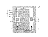
図1(a)は、本実施形態に係る流量測定装置1を示す分解斜視図であり、図1(b)は、図1(a)に示される流量測定装置1を示す透視図である。
FIG. 1A is an exploded perspective view showing a flow
図1(a)(b)に示されるように、流量測定装置1は、主流路21が形成された主流路部2と、副流路31が形成された副流路部3と、シール4と、回路基板5と、カバー6とを備えている。
As shown in FIGS. 1A and 1B, the flow
主流路部2は、長手方向に貫通した主流路21が内部に形成された管状部材である。主流路部2の内周面には、測定対象流体の流れ方向Oに対して、上流側に流入口(第1流入口)34Aが形成され、下流側に流出口(第1流出口)35Aが形成されている。
The main
なお、本実施形態では、主流路部2の軸方向の長さは約50mmであり、内周面の直径(主流路21の直径)は約20mmであり、主流路部2の外周面の直径は約24mmである。
In the present embodiment, the axial length of the
副流路部3は、主流路部2の上に設けられており、その内部および上面には、副流路31が形成されている。副流路31は、流入口34Aに連通し、他端が流出口35Aに連通している。流量測定装置1では、副流路31は、流入用流路34と、物性値検出用流路32と、流量検出用流路33と、流出用流路35とから構成されている。
The sub
流入用流路34は、主流路21を流れる測定対象流体を流入させて、物性値検出用流路32および流量検出用流路33に分流させるための流路である。流入用流路34は、主流路21と垂直な方向に、副流路部3を貫通して形成されており、一端が流入口34Aに連通し、他端は主流路部2の上面で開口して、物性値検出用流路32および流量検出用流路33に連通している。これにより、主流路21を流れる測定対象流体の一部を、流入用流路34を介して、物性値検出用流路32および流量検出用流路33に分流させることができる。
The
物性値検出用流路(物性値検出流路)32は、副流路部3の上面に形成された、主流路21と平行な方向に延在する略コの字型の流路である。物性値検出用流路32は、長手方向(主流路21と平行な方向)に延在する部分に、測定対象流体の物性値を検出するための物性値センサ7が配置された物性値検出領域36を有している。物性値検出用流路32の一端は、流入用流路34を介して流入口34Aに連通しており、他端は、流出用流路35を介して流出口35Aに連通している。
The physical property value detection flow path (physical property value detection flow path) 32 is a substantially U-shaped flow path formed on the upper surface of the sub
流量検出用流路(流量検出流路)33は、副流路部3の上面に形成された、主流路21と平行な方向に延在する略コの字型の流路である。流量検出用流路33は、長手方向(主流路21と平行な方向)に延在する部分に、測定対象流体の流量を検出するための流量センサ8が配置された流量検出領域37を有している。流量検出用流路33の一端は、流入用流路34を介して流入口34Aに連通しており、他端は、流出用流路35を介して流出口35Aに連通している。
The flow rate detection flow path (flow rate detection flow path) 33 is a substantially U-shaped flow path formed on the upper surface of the sub
なお、図面では、説明の便宜上、物性値センサ7および流量センサ8と、回路基板5とが分離された状態で図示しているが、物性値センサ7および流量センサ8は、回路基板5に実装された状態で物性値検出領域36または流量検出領域37に配置されている。
In the drawing, for convenience of explanation, the physical
流出用流路35は、物性値検出用流路32および流量検出用流路33を通過した測定対象流体を、主流路21に流出させるための流路である。流出用流路35は、主流路21と垂直な方向に、副流路部3を貫通して形成されており、一端が流出口35Aに連通し、他端は主流路部2の上面で開口して、物性値検出用流路32および流量検出用流路33に連通している。これにより、物性値検出用流路32および流量検出用流路33を通過した測定対象流体を、流出用流路35を介して、主流路21に流出させることができる。
The
このように、同じ流入口34Aから流入させた測定対象流体を、物性値検出用流路32および流量検出用流路33に分流させることで、物性値センサ7および流量センサ8は、温度、濃度などの条件が等しい測定対象流体に基づいて物性値および流量を検出することができる。したがって、流量測定装置1の測定精度を向上させることができる。
In this way, the physical
なお、流量測定装置1では、副流路部3にシール4を嵌め込んだ後、回路基板5が配置され、さらにカバー6によって回路基板5を副流路部3に固定することで、副流路部3の内部の気密性を確保している。
In the flow
図2は、図1(a)に示される副流路部3を示す斜視図である。図2に示されるように、物性値検出用流路32は、略コの字型の一端が流入用流路34に連通し、他端が流出用流路35に連通している。同様に、流量検出用流路33は、略コの字型の一端が流入用流路34に連通し、他端が流出用流路35に連通している。
FIG. 2 is a perspective view showing the auxiliary
また、物性値検出用流路32と流量検出用流路33との両端部も互いに連通しており、物性値検出用流路32および流量検出用流路33は、副流路部3の上面において矩形状の流路を構成している。
Further, both end portions of the physical property value
流量測定装置1では、物性値検出領域36および流量検出領域37は、何れも副流路部3の上面と垂直な方向から見たときの形状が正方形であり、流入用流路34と流出用流路35とを結ぶ直線に対して対象となる位置にそれぞれ形成されている。
In the flow
なお、本実施形態では、物性値検出領域36および流量検出領域37の一辺の長さは、何れも約4mmである。
In the present embodiment, the lengths of one side of the physical property
また、本実施形態では、物性値検出領域36および流量検出領域37の形状を正方形としているが、本発明はこれに限定されない。物性値検出領域36および流量検出領域37の形状は、物性値センサ7および流量センサ8が配置可能であればよく、配置される物性値センサ7および流量センサ8の形状に応じて決定される。
In the present embodiment, the physical property
したがって、例えば、物性値検出用流路32の幅よりも、物性値センサ7のサイズが小さい場合には、物性値検出領域36の幅を物性値検出用流路32の幅に一致させてもよい。この場合、物性値検出用流路32の長手方向に延在する部分は、直線形状に形成されることとなる。なお、流量検出領域37についても同様である。
Therefore, for example, when the size of the physical
図3(a)は、図2に示される物性値センサ7の概略構成を示す上面図であり、図3(b)は、図2に示される流量センサ8の概略構成を示す上面図である。
FIG. 3A is a top view showing a schematic configuration of the
図3(a)に示されるように、物性値センサ7は、測定対象流体を加熱するマイクロヒータ(加熱部)71と、測定対象流体の温度を検出する第1物性値サーモパイル(温度検出部)72および第2物性値サーモパイル(温度検出部)73とを備えている。マイクロヒータ71と、第1物性値サーモパイル72および第2物性値サーモパイル73とは、物性値検出領域36において、測定対象流体の流れ方向と直交する方向に並んで配置されている。
As shown in FIG. 3A, the physical
第1物性値サーモパイル72および第2物性値サーモパイル73は、マイクロヒータ71を挿んで左右対称に配置されており、マイクロヒータ71の両側の対称な位置の温度を検出する。
The first physical
ここで、測定対象流体の流れによって温度分布は下流側に偏るため、流れ方向と直交する方向の温度分布の変化は、測定対象流体の流れ方向の温度分布の変化に比べて小さい。このため、第1物性値サーモパイル72と、マイクロヒータ71と、第2物性値サーモパイル73とを、この順で測定対象流体の流れ方向と直交する方向に並んで配置することにより、温度分布の変化による第1物性値サーモパイル72および第2物性値サーモパイル73の出力特性の変化を低減することができる。したがって、測定対象流体の流れによる温度分布の変化の影響を低減して、物性値センサ7による検出精度を向上させることができる。
Here, since the temperature distribution is biased to the downstream side due to the flow of the measurement target fluid, the change in the temperature distribution in the direction orthogonal to the flow direction is smaller than the change in the temperature distribution in the flow direction of the measurement target fluid. For this reason, the first physical
また、マイクロヒータ71の長手方向が測定対象流体の流れ方向に沿って配置されているため、マイクロヒータ71は測定対象流体の流れ方向に亘って広範囲に測定対象流体を加熱することが可能となる。このため、測定対象流体の流れによって温度分布が下流側に偏った場合であっても、第1物性値サーモパイル72および第2物性値サーモパイル73の出力特性の変化を低減することができる。したがって、測定対象流体の流れによる温度分布の変化の影響を低減して、測定対象流体の流れによる温度分布の変化の影響を低減して、物性値センサ7による検出精度を向上させることができる。
In addition, since the longitudinal direction of the
さらに、第1物性値サーモパイル72および第2物性値サーモパイル73の長手方向が測定対象流体の流れ方向に沿って配置されているため、第1物性値サーモパイル72および第2物性値サーモパイル73は測定対象流体の流れ方向に亘って広範囲に温度を検出することが可能となる。このため、測定対象流体の流れによって温度分布が下流側に偏った場合であっても、第1物性値サーモパイル72および第2物性値サーモパイル73の出力特性の変化を低減することができる。したがって、測定対象流体の流れによる温度分布の変化の影響を低減して、物性値センサ7による検出精度を向上させることができる。
Furthermore, since the longitudinal directions of the first physical
一方、図3(b)に示されるように、流量センサ8は、測定対象流体を加熱するマイクロヒータ81と、測定対象流体の温度を検出する第1流量サーモパイル82および第2流量サーモパイル83とを備えている。マイクロヒータ81と、第1流量サーモパイル82および第2流量サーモパイル83とは、流量検出領域37において、測定対象流体の流れ方向に並んで配置されている。
On the other hand, as shown in FIG. 3B, the
第1流量サーモパイル82および第2流量サーモパイル83は、マイクロヒータ81の上流側に第1流量サーモパイル82が配置され、下流側に第2流量サーモパイル83が配置されて、マイクロヒータ81を挿んで対称な位置の温度を検出する。
The
流量測定装置1では、物性値センサ7および流量センサ8に、実質的に同一構造のセンサが用いられており、測定対象流体の流れ方向に対する配置角度を90°異ならせて配置されている。これにより、同一構造のセンサを物性値センサ7または流量センサ8として機能させることが可能となるため、流量測定装置1の製造コストを低減することができる。
In the flow
ここで、流量測定装置1では、物性値検出用流路32と流量検出用流路33とは、長手方向に延在する流路の幅がそれぞれ異なっており、物性値検出用流路32の物性値センサ7が配置された流路の幅は、流量検出用流路33の流量センサ8が配置された流路の幅よりも狭くなっている。これにより、流量測定装置1では、物性値検出用流路32および流量検出用流路33に分流される測定対象流体の流量を、それぞれ個別に制御されている。
Here, in the flow
図4は、図2に示される物性値検出用流路32および流量検出用流路33に分流する測定対象流体の流量を説明するための模式図である。図4に示されるように、本実施形態では、物性値検出用流路32には流量Pの測定対象流体が分流され、流量検出用流路33には流量Qの測定対象流体が流れるように、物性値検出用流路32および流量検出用流路33の幅が設定されている。
FIG. 4 is a schematic diagram for explaining the flow rate of the measurement target fluid that is divided into the physical property value
この流量Pおよび流量Qの値は、主流路21を流れる測定対象流体の流量によって変動するものであるが、通常の使用態様において、流量Pは物性値センサ7の検出レンジ内の値となり、流量Qは流量センサ8の検出レンジ内の値となるように、物性値検出用流路32および流量検出用流路33の幅がそれぞれ設定されている。
The values of the flow rate P and the flow rate Q vary depending on the flow rate of the fluid to be measured flowing through the
なお、本実施形態では、物性値検出用流路32の幅は約0.4mmであり、流量検出用流路33の幅は約0.8mmである。
In the present embodiment, the width of the physical property
このように、流量測定装置1では、物性値検出用流路32および流量検出用流路33に分流する測定対象流体の流量を、それぞれの幅を調整することで個別に制御することが可能である。このため、物性値センサ7の検出レンジに応じて物性値検出領域36を流れる測定対象流体の流量を制御し、流量センサ8の検出レンジに応じて流量検出領域37を流れる測定対象流体の流量を制御することができる。
As described above, in the flow
したがって、物性値センサ7は、固有の検出レンジに応じた最適な流量で、測定対象流体の物性値を検出することができるので、物性値センサ7の検出精度を高めることができる。
Therefore, since the physical
同様に、流量センサ8は、固有の検出レンジに応じた最適な流量で、測定対象流体の流量を検出することができるので、物性値センサ7の検出精度を高めることができる。
Similarly, the
図5は、図4に示される物性値センサ7および流量センサ8の出力値と流量との関係を示すグラフである。図5では、横軸が流量(%)、縦軸が各センサの出力値(%)を規定しており、物性値センサ7および流量センサ8の検出レンジの最大流量を100%、最大流量時のセンサ出力値を100%として規定している。
FIG. 5 is a graph showing the relationship between the output values of the
図5に示されるように、流量センサ8の出力値は、流量検出領域37を流れる測定対象流体の流量の増加に伴って増加するのに対して、物性値センサ7の出力値は、物性値検出領域36を流れる測定対象流体の流量変化の影響を受けず一定である。
As shown in FIG. 5, the output value of the
このように、流量測定装置1によれば、物性値センサ7は、測定対象流体の流量変化の影響を受けることなく測定対象流体の物性値を検出することができるので、物性値の検出精度を高めることができる。
As described above, according to the
(2)制御部の構成
次に、流量測定装置1が備える制御部の構成を、図6を参照して説明する。図6は、図1に示される流量測定装置1が備える制御部51の要部構成を示すブロック図である。図6に示されるように、制御部51は、流量算出部52と、物性値算出部53と、流量補正部54とを備えている。物性値算出部53は、第1物性値サーモパイル72および第2物性値サーモパイル73に接続されている。また、流量算出部52は、第1流量サーモパイル82および第2流量サーモパイル83に接続されている。
(2) Structure of control part Next, the structure of the control part with which the
流量算出部52は、第1流量サーモパイル82および第2流量サーモパイル83から出力された温度検出信号に基づいて、測定対象流体の流量を算出するものである。具体的には、流量算出部52は、第1流量サーモパイル82から出力された温度検出信号と第2流量サーモパイル83から出力された温度検出信号との差分を算出し、温度検出信号の差分に基づいて、測定対象流体の流量を算出する。そして、流量算出部52は、算出した測定対象流体の流量を流量補正部54に出力する。
The flow
物性値算出部53は、第1物性値サーモパイル72および第2物性値サーモパイル73から出力された温度検出信号に基づいて、測定対象流体の物性値を算出するものである。具体的には、物性値算出部53は、第1物性値サーモパイル72および第2物性値サーモパイル73から出力された温度検出信号の平均値に基づいて、熱伝導率、熱拡散、または比熱などによって決定される物性値(例えば、熱拡散定数など)を算出する。物性値算出部53は、算出した測定対象流体の物性値を流量補正部54に出力する。
The physical property
流量補正部54は、物性値算出部53から出力された測定対象流体の物性値を用いて、流量算出部52から出力された測定対象流体の流量を補正するものである。具体的には、流量補正部54は、物性値算出部53から測定対象流体の物性値が出力されたとき、当該物性値を用いて、流量算出部52から出力された測定対象流体の流量を補正し、補正後の流量を算出する。
The flow
(3)流量測定装置の処理
次に、流量測定装置1が備える制御部51の処理の流れについて、図7を参照して説明する。図7は、図6に示される制御部51の処理の流れを示すフローチャートである。
(3) Process of Flow Measuring Device Next, the flow of processing of the
図7に示されるように、流量算出部52は、第1流量サーモパイル82および第2流量サーモパイル83から温度検出信号が出力されたとき、2つの温度検出信号に基づいて、測定対象流体の流量を算出する(S1)。
As shown in FIG. 7, when the temperature detection signals are output from the first
具体的には、流量算出部52は、第1流量サーモパイル82から出力された温度検出信号と第2流量サーモパイル83から出力された温度検出信号との差分を算出する。さらに、流量算出部52は、算出した温度検出信号の差分に基づいて、測定対象流体の流量を算出する。
Specifically, the flow
なお、第1流量サーモパイル82および第2流量サーモパイル83から出力された温度検出信号に基づいて測定対象流体の流量を算出する手法は、公知のものを用いることができる。流量算出部52は、算出した測定対象流体の流量を流量補正部54に出力する。
Incidentally, methods of calculating the flow rate of the measurement target fluid based on the temperature detection signal outputted from the
また、物性値算出部53は、第1物性値サーモパイル72および第2物性値サーモパイル73から温度検出信号が出力されたとき、2つの温度検出信号の平均値に基づいて、測定対象流体の物性値を算出する(S2)。
In addition, when the temperature detection signal is output from the first physical
測定対象流体を伝わる熱の速度は、熱伝導率、熱拡散または比熱などによって決定される熱拡散定数などの物性値に対応しているため、マイクロヒータ71と、第1物性値サーモパイル72および第2物性値サーモパイル73との温度差を検出することによって、熱拡散定数を求めることができる。例えば、マイクロヒータ71と、第1物性値サーモパイル72および第2物性値サーモパイル73との温度差が大きいほど、熱拡散定数(熱伝導率)は小さくなる。
Since the speed of the heat transmitted through the fluid to be measured corresponds to a physical property value such as a thermal diffusion constant determined by thermal conductivity, thermal diffusion, specific heat, or the like, the
このような性質を利用して、測定対象流体の流れ方向と直交する方向に配置された第1物性値サーモパイル72および第2物性値サーモパイル73によって測定対象流体の温度を検出することにより、測定対象流体の物性値を算出することができる。
By utilizing such properties, the temperature of the measurement target fluid is detected by the first physical
ここで、流量測定装置1では、物性値センサ7の検出レンジに応じて物性値検出領域36を流れる測定対象流体の流量が制御されているため、第1物性値サーモパイル72および第2物性値サーモパイル73は、測定対象流体の流量の影響を受けずにマイクロヒータ71から発せられた熱を検出することができる。
Here, in the flow
このため、第1物性値サーモパイル72および第2物性値サーモパイル73は、一定の出力特性を維持したまま、温度検出信号を物性値算出部53に出力することができるので、物性値算出部53は、高い精度をもって物性値を算出することができる。物性値算出部53は、算出した測定対象流体の物性値を流量補正部54に出力する。
For this reason, the first physical
次に、流量補正部54は、物性値算出部53から測定対象流体の物性値が出力されたとき、当該物性値を用いて、流量算出部52から出力された測定対象流体の流量を補正し、補正後の流量を算出する(S3)。具体的には、流量補正部54は、下記の計算式(2)を用いて、補正後の流量を算出する。
Next, when the physical property value of the measurement target fluid is output from the physical property
![]()
![]()
このように、流量測定装置1では、物性値センサ7の出力特性が測定対象流体の流量の影響を受けないため、流量補正部54は、従来のように、物性値算出部53から出力された測定対象流体の物性値に対して流量に応じた補正を行うことなく、流量算出部52から出力された測定対象流体の流量を補正することができる。
As described above, in the flow
したがって、流量測定装置1によれば、流量センサ8によって検出された測定対象流体の流量を、物性値センサ7によって検出された物性値に基づいて適切に補正することができるため、測定対象流体の流量を高精度に測定することができる。
Therefore, according to the flow
(4)総括
以上のように、本実施形態に係る流量測定装置1は、主流路21を流れる測定対象流体の流量を検出するための流量センサ8と、測定対象流体を加熱するマイクロヒータ71および測定対象流体の温度を検出する第1物性値サーモパイル72・第2物性値サーモパイル73を有する、測定対象流体の物性値を検出するための物性値センサ7と、一端が主流路21内に開口した流入口34Aに連通し、且つ、他端が主流路21内に開口した流出口35Aに連通した、物性値センサ7が配置された物性値検出用流路32を有する副流路部3と、物性値センサ7から出力された検出信号に基づいて算出された測定対象流体の物性値を用いて、流量センサ8から出力された検出信号に基づいて算出された測定対象流体の流量を補正する流量補正部54と、を備え、マイクロヒータ71および第1物性値サーモパイル72・第2物性値サーモパイル73は、測定対象流体の流れ方向と直交する方向に並んで配置されており、流量センサ8は、物性値検出用流路32を除く位置に配置されている。
(4) Summary As described above, the flow
流量測定装置1では、物性値センサ7は物性値検出用流路32に配置され、流量センサ8は流量検出用流路33に配置されている。このため、例えば、物性値検出用流路32の幅を調整して物性値検出用流路32を流れる測定対象流体の流量を制御することで、流量の影響によって物性値センサ7の出力特性が変化することを抑止することができ、さらに、測定対象流体の流れによる乱流の発生を効果的に抑制することが可能となる。
In the flow
したがって、流量測定装置1によれば、流量補正部54は、物性値センサ7から出力された温度検出信号に基づいて算出された精度の高い物性値を用いて、流量センサ8から出力された温度検出信号に基づいて算出された測定対象流体の流量を正確に補正することができる。
Therefore, according to the flow
また、流量測定装置1では、物性値センサ7は、一端が主流路21内に開口した流入口34Aに連通し、且つ、他端が主流路21内に開口した流出口35Aに連通した、物性値検出用流路32に配置されている。このため、測定対象流体の流れが停滞することなく、流入口34Aから流出口35Aへ流れるため、物性値センサ7周辺に存在する測定対象流体の置換を効率的に行うことができる。
In the flow
したがって、流量測定装置1によれば、主流路21を流れる測定対象流体の物性値が変化した場合であっても、適切な物性値に基づいて、測定対象流体の流量を正確に補正することが可能となる。
Therefore, according to the flow
さらに、測定対象流体の流れによって温度分布は下流側に偏るため、流れ方向と直交する方向の温度分布の変化は、測定対象流体の流れ方向の温度分布の変化に比べて小さいため、第1物性値サーモパイル72と、マイクロヒータ71と、第2物性値サーモパイル73とを、測定対象流体の流れ方向と直交する方向に並んで配置することにより、温度分布の変化による第1物性値サーモパイル72および第2物性値サーモパイル73の出力特性の変化を低減することができる。したがって、測定対象流体の流れによる温度分布の変化の影響を低減して、物性値センサ7による検出精度を向上させることができる。
Furthermore, since the temperature distribution is biased to the downstream side due to the flow of the measurement target fluid, the change in the temperature distribution in the direction orthogonal to the flow direction is smaller than the change in the temperature distribution in the flow direction of the measurement target fluid. The
それゆえ、本実施形態によれば、測定対象流体の物性変化による出力特性の変化を低減して、高精度に測定対象流体の流量を測定することができる流量測定装置1を実現することができる。
Therefore, according to the present embodiment, it is possible to realize the flow
(5)変形例
次に、本実施形態に係る流量測定装置1の変形例について、図8および図9を参照して説明する。
(5) Modified Example Next, a modified example of the flow
(5−1)変形例1
本実施形態では、図4に示されるように、物性値検出用流路32および流量検出用流路33が、何れも略コの字型に形成された構成について説明したが、本発明はこれに限定されない。物性値検出用流路32および流量検出用流路33は、物性値検出領域36および流量検出領域37を通過する測定対象流体の流量が制御可能な幅に設定されていれば、その形状は特に限定されない。
(5-1)
In the present embodiment, as shown in FIG. 4, the configuration in which the physical property
図8(a)〜(d)は、図4に示される副流路部3の上面に形成された、物性値検出用流路32および流量検出用流路33の変形例を示す上面図である。
8A to 8D are top views showing modifications of the physical property value
図8(a)に示されるように、例えば、物性値検出用流路32を直線状に形成し、流量検出用流路33を略コの字型に形成してもよい。
As shown in FIG. 8A, for example, the physical property
また、図8(b)〜図8(d)に示されるように、流量検出領域37に対して測定対象流体を流入させる方向と直交する方向から物性値検出領域36に対して測定対象流体を流入させるように、物性値検出用流路32を形成してもよい。
Further, as shown in FIG. 8 (b) ~ FIG 8 (d), measured fluid from a direction direction Cartesian flowing a measurement target fluid against the flow
この場合、物性値センサ7と流量センサ8との配置角度を一致させることができるため、流量測定装置1の製造過程において、回路基板5に物性値センサ7および流量センサ8を実装する工程を簡略化することができる。
In this case, since the arrangement angles of the physical
(5−2)変形例2
本実施形態では、図3(a)に示されるように、物性値センサ7は、測定対象流体を加熱するマイクロヒータ71と、測定対象流体の温度を検出する第1物性値サーモパイル72および第2物性値サーモパイル73とを備え、第1物性値サーモパイル72および第2物性値サーモパイル73が、マイクロヒータ71を挿んで左右対称に配置された構成について説明したが、本発明はこれに限定されない。
(5-2)
In the present embodiment, as shown in FIG. 3A, the physical
図9は、図3(a)に示される物性値センサ7の変形例の概略構成を示す上面図である。図9に示されるように、第2物性値サーモパイル73を省略して、マイクロヒータ71と、第1物性値サーモパイル72とで、物性値センサ7aを構成してもよい。
FIG. 9 is a top view showing a schematic configuration of a modified example of the
このように、マイクロヒータ71と第1物性値サーモパイル72を、測定対象流体の流れ方向と直交する方向に並べて配置することで、物性値センサ7aを実現してもよい。
In this manner, the physical
〔実施形態2〕
本発明に係る流量測定装置の第二の実施形態について、図10に基づいて説明すれば、以下のとおりである。なお、実施形態1と同様の部材に関しては、同じ符号を付し、その説明を省略する。
[Embodiment 2]
The second embodiment of the flow rate measuring device according to the present invention will be described below with reference to FIG. In addition, about the member similar to
本実施形態に係る流量測定装置は、流量センサが主流路に配置される点で、実施形態1に係る流量測定装置と異なっている。 The flow measurement device according to the present embodiment is different from the flow measurement device according to the first embodiment in that a flow sensor is disposed in the main flow path.
図10(a)は、本実施形態に係る流量測定装置1aを示す斜視図であり、図10(b)は、図10(a)に示される流量測定装置1aを示す断面図であり、図10(c)は、図10(a)に示される副流路部3aを示す上面図である。
FIG. 10A is a perspective view showing a flow rate measuring device 1a according to this embodiment, and FIG. 10B is a cross-sectional view showing the flow rate measuring device 1a shown in FIG. 10 (c) is a top view showing the
図10(a)〜図10(c)に示されるように、流量測定装置1aでは、主流路部2aの内周面の流入口34Aと流出口35Aとの間に、開口部37Aが形成されている。
As shown in FIGS. 10A to 10C, in the flow rate measuring device 1a, an
副流路部3aの内部には、流量センサ8が配置されたセル状の流量検出領域37aが形成されており、流量検出領域37aは開口部37Aに連通している。このため、流量検出領域37aには、開口部37Aを介して主流路21aを流れる測定対象流体が流入し、流量センサ8によってその流量が検出される。
A cell-like flow
なお、開口部37Aの大きさを制御調整することによって、主流路21aから流量検出領域37aに流入する測定対象流体の流量を制御することができる。
The flow rate of the measurement target fluid flowing from the
副流路31aは、流入用流路34と、物性値検出用流路32と、流出用流路35とから構成されており、物性値検出用流路32は、長手方向に延在する流路に、測定対象流体の物性値を検出するための物性値センサ7が配置された物性値検出領域36を有している。
The sub-channel 31a includes an
このように、流量測定装置1aでは、物性値センサ7が副流路31aに配置され、流量センサ8が主流路21aに配置されている。このため、流量測定装置1aでは、物性値センサ7の検出レンジに応じた流量を制御することが可能である。
Thus, in the flow measuring device 1a, the
それゆえ、本実施形態によれば、測定対象流体の物性変化による出力特性の変化を低減して、高精度に測定対象流体の流量を測定することができる流量測定装置1aを実現することができる。 Therefore, according to the present embodiment, it is possible to realize the flow rate measuring device 1a that can reduce the change in the output characteristics due to the change in the physical properties of the measurement target fluid and can measure the flow rate of the measurement target fluid with high accuracy. .
〔実施形態3〕
本発明に係る流量測定装置の第三の実施形態について、図11に基づいて説明すれば、以下のとおりである。なお、実施形態1および2と同様の部材に関しては、同じ符号を付し、その説明を省略する。
[Embodiment 3]
It will be as follows if 3rd embodiment of the flow measuring device which concerns on this invention is described based on FIG. In addition, about the member similar to
本実施形態に係る流量測定装置は、独立した2つの副流路を有する点で、実施形態1および2に係る流量測定装置と異なっている。 The flow measurement device according to the present embodiment is different from the flow measurement devices according to the first and second embodiments in that the flow measurement device according to the present embodiment has two independent sub-flow channels.
図11(a)は、本実施形態に係る流量測定装置1bを示す斜視図であり、図11(b)は、図11(a)に示される副流路部3を示す上面図である。
FIG. 11A is a perspective view showing the flow rate measuring device 1b according to the present embodiment, and FIG. 11B is a top view showing the
図11(a)および図11(b)に示されるように、流量測定装置1bでは、副流路部3bは、その内部および上面に第1副流路31bおよび第2副流路31Bが形成されている。
As shown in FIG. 11 (a) and 11 (b), the flow measuring device 1 b, the auxiliary
第1副流路31bは、流入用流路34bと、物性値検出用流路32bと、流出用流路35bとから構成されており、物性値検出用流路32bは、長手方向に延在する流路に、測定対象流体の物性値を検出するための物性値センサ7が配置された物性値検出領域36を有している。
The first sub-channel 31b includes an
第2副流路31Bは、流入用流路34Bと、流量検出用流路33Bと、流出用流路35Bとから構成されており、流量検出用流路33Bは、長手方向に延在する流路に、測定対象流体の流量を検出するための流量センサ8が配置された流量検出領域37を有している。
The
このように、流量測定装置1bでは、副流路部3bが独立した2つの副流路である第1副流路31bおよび第2副流路31Bを有しており、物性値センサ7が第1副流路31bに配置され、流量センサ8が第2副流路31Bに配置されている。このため、流量測定装置1bによれば、物性値センサ7および流量センサ8の検出レンジに応じた流量を、個別に制御することが可能である。
As described above, in the flow rate measuring device 1b, the
それゆえ、本実施形態によれば、測定対象流体の物性変化による出力特性の変化を低減して、高精度に測定対象流体の流量を測定することができる流量測定装置1bを実現することができる。 Therefore, according to the present embodiment, it is possible to realize the flow rate measuring device 1b that can reduce the change in the output characteristics due to the change in the physical properties of the measurement target fluid and can measure the flow rate of the measurement target fluid with high accuracy. .
〔実施形態4〕
本発明に係る流量測定装置の第四の実施形態について、図12に基づいて説明すれば、以下のとおりである。なお、実施形態1〜3と同様の部材に関しては、同じ符号を付し、その説明を省略する。
[Embodiment 4]
It will be as follows if 4th embodiment of the flow measuring device concerning this invention is described based on FIG. In addition, about the member similar to Embodiment 1-3, the same code | symbol is attached | subjected and the description is abbreviate | omitted.
本実施形態に係る流量測定装置は、物性値検出用流路が、流量検出用流路内に形成されている点で、実施形態1〜3に係る流量測定装置と異なっている。 The flow measurement device according to the present embodiment is different from the flow measurement devices according to the first to third embodiments in that the physical property value detection flow path is formed in the flow detection flow path.
図12(a)は、本実施形態に係る流量測定装置1cを示す斜視図であり、図12(b)は、図12(a)に示される副流路部3cを示す斜視図であり、図12(c)は、図12(a)に示される副流路部3cを示す上面図である。
FIG. 12 (a) is a perspective view showing a flow rate measuring device 1c according to the present embodiment, FIG. 12 (b) is a perspective view showing a
図12(a)〜図12(c)に示されるように、流量測定装置1cでは、副流路部3cは、その内部および上面に副流路(第1副流路)31cが形成されている。
As shown in FIGS. 12A to 12C, in the flow rate measuring device 1c, the sub
副流路31cは、流入用流路34と、物性値検出用流路32cと、流量検出用流路33cと、流出用流路35とから構成されている。
The
副流路31cでは、物性値検出用流路32cが、流量検出用流路33c内の流量検出領域37cに形成されており、測定対象流体の流れ方向に対して上流側に流量センサ8が配置され、下流側に物性値センサ7が配置されている。
In the
ここで、物性値検出用流路32cは、測定対象流体の流量を制御するための流量制御部材40によって、流量検出領域37cと仕切られており、物性値センサ7は流量制御部材40の内部に配置されている。
Here, the physical property value
流量制御部材40は、物性値検出領域36cを通過する測定対象流体の流量を制御するためのものであり、第1側壁部40aと第2側壁部40bとから構成されている。第1側壁部40aおよび第2側壁部40bは何れも略コの字型の板状部材であり、それぞれの端部を対向させた状態で、所定の間隔をおいて配置されている。
The flow
したがって、第1側壁部40aと第2側壁部40bとの間隔を制御することによって、流量制御部材40の内部、すなわち、物性値検出領域36cを通過する測定対象流体の流量を調整することができる。
Therefore, by controlling the distance between the first
このように、流量測定装置1cでは、副流路部3cが副流路31c内に、流量制御部材40を備え、流量制御部材40の内部に物性値検出領域36cが設けられているため、副流路31c内の任意の位置に物性値検出領域36cを設けることが可能となる。また、流量制御部材40を備えることで、物性値検出領域36cを通過する測定対象流体の流量を容易に制御することができる。
As described above, in the flow rate measuring device 1c, the sub
このように、物性値検出用流路32cが、流量検出用流路33c内に形成されて構成デっても、物性値センサ7および流量センサ8の検出レンジに応じた流量を個別に制御することが可能である。
As described above, even if the physical property value
それゆえ、本実施形態によれば、測定対象流体の物性変化による出力特性の変化を低減して、高精度に測定対象流体の流量を測定することができる流量測定装置1cを実現することができる。 Therefore, according to the present embodiment, it is possible to realize the flow rate measuring device 1c that can measure the flow rate of the measurement target fluid with high accuracy by reducing the change in the output characteristic due to the change in the physical property of the measurement target fluid. .
本発明は、上述した実施形態に限定されるものではなく、請求項に示した範囲で種々の変更が可能であり、異なる実施形態にそれぞれ開示された技術的手段を適宜組み合わせて得られる実施形態についても本発明の技術的範囲に含まれる。 The present invention is not limited to the above-described embodiments, and various modifications can be made within the scope shown in the claims, and the embodiments can be obtained by appropriately combining technical means disclosed in different embodiments. Is also included in the technical scope of the present invention.
本発明に係る流量測定装置は、ガスメータ、燃焼機器、自動車内燃機関、または燃料電池などに好適に利用することがきる。 The flow rate measuring device according to the present invention can be suitably used for a gas meter, a combustion device, an automobile internal combustion engine, a fuel cell, or the like.
1 流量測定装置
3 副流路部
3a 副流路部
3b 副流路部
3c 副流路部
7 物性値センサ(物性値検出部)
8 流量センサ(流量検出部)
21 主流路
31 副流路
31a 副流路
31b 第1副流路
31B 第2副流路
31c 副流路
32 物性値検出用流路(物性値検出流路)
32b 物性値検出用流路(物性値検出流路)
32c 物性値検出用流路(物性値検出流路)
33 流量検出用流路(流量検出流路)
33B 流量検出用流路(流量検出流路)
33c 流量検出用流路(流量検出流路)
34 流入用流路
34A 流入口(第1流入口)
35 流出用流路
35A 流出口(第1流出口)
36 物性値検出領域
54 流量補正部
71 マイクロヒータ(加熱部)
72 第1物性値サーモパイル(温度検出部)
73 第2物性値サーモパイル(温度検出部)
DESCRIPTION OF
8 Flow rate sensor (Flow rate detector)
21
32b Physical property value detection flow path (property value detection flow path)
32c Physical property value detection channel (Physical property value detection channel)
33 Flow rate detection flow path (flow rate detection flow path)
33B Flow rate detection flow path (flow rate detection flow path)
33c Flow rate detection flow path (flow rate detection flow path)
34
35
36 Physical
72 The first physical property value thermopile (temperature detector)
73 Second physical property thermopile (temperature detector)
Claims (6)
測定対象流体を加熱する加熱部および測定対象流体の温度を検出する温度検出部を有する、測定対象流体の物性値を検出するための物性値検出部と、
一端が前記主流路内に開口した第1流入口に連通し、且つ、他端が前記主流路内に開口した第1流出口に連通した、前記物性値検出部が配置された物性値検出流路を有する副流路部と、
前記物性値検出部から出力された検出信号に基づいて算出された測定対象流体の物性値を用いて、前記流量検出部から出力された検出信号に基づいて算出された測定対象流体の流量を補正する流量補正部と、
を備え、
前記加熱部および前記温度検出部は、測定対象流体の流れ方向と直交する方向に並んで配置されており、
前記流量検出部は、前記物性値検出流路を除く位置に配置されており、
前記副流路部は、前記流量検出部が配置された流量検出流路をさらに有しており、
前記物性値検出流路および前記流量検出流路は、前記主流路の外部に設けられていることを特徴とする流量測定装置。 A flow rate detector for detecting the flow rate of the fluid to be measured flowing through the main flow path;
A physical property value detection unit for detecting a physical property value of the measurement target fluid, having a heating unit for heating the measurement target fluid and a temperature detection unit for detecting the temperature of the measurement target fluid;
A physical property value detection flow in which the physical property value detection unit is disposed, one end of which communicates with a first inlet opening in the main flow channel and the other end of which communicates with a first flow outlet opened in the main flow channel. A sub-flow channel portion having a path;
Using the physical property value of the measurement target fluid calculated based on the detection signal output from the physical property value detection unit, the flow rate of the measurement target fluid calculated based on the detection signal output from the flow rate detection unit is corrected. A flow rate correction unit,
With
The heating unit and the temperature detection unit are arranged side by side in a direction orthogonal to the flow direction of the measurement target fluid,
The flow rate detection unit is arranged at a position excluding the physical property value detection flow path ,
The sub-flow channel unit further includes a flow rate detection flow channel in which the flow rate detection unit is disposed,
The flow rate measuring device, wherein the physical property value detection flow path and the flow rate detection flow path are provided outside the main flow path .
前記第1流入口から流入した測定対象流体を、前記物性値検出流路および前記流量検出流路に分流させることを特徴とする請求項1に記載の流量測定装置。 The flow rate detection channel has one end communicating with the first inflow port and the other end communicating with the first outflow port,
The flow rate measuring device according to claim 1, wherein the fluid to be measured that has flowed from the first inflow port is divided into the physical property value detection flow path and the flow rate detection flow path.
前記流量検出流路内を流れる測定対象流体の一部を前記物性値検出流路に流入させることを特徴とする請求項2に記載の流量測定装置。 The physical property value detection flow path is provided in the flow rate detection flow path,
The flow rate measuring apparatus according to claim 2, wherein a part of the fluid to be measured that flows in the flow rate detection channel is caused to flow into the physical property value detection channel.
Priority Applications (4)
| Application Number | Priority Date | Filing Date | Title |
|---|---|---|---|
| JP2011101998A JP5652315B2 (en) | 2011-04-28 | 2011-04-28 | Flow measuring device |
| EP12776213.6A EP2703786B1 (en) | 2011-04-28 | 2012-04-18 | Flow rate measuring device |
| US14/112,243 US9068871B2 (en) | 2011-04-28 | 2012-04-18 | Flow rate measuring device |
| PCT/JP2012/060470 WO2012147586A1 (en) | 2011-04-28 | 2012-04-18 | Flow rate measuring device |
Applications Claiming Priority (1)
| Application Number | Priority Date | Filing Date | Title |
|---|---|---|---|
| JP2011101998A JP5652315B2 (en) | 2011-04-28 | 2011-04-28 | Flow measuring device |
Publications (3)
| Publication Number | Publication Date |
|---|---|
| JP2012233776A JP2012233776A (en) | 2012-11-29 |
| JP2012233776A5 JP2012233776A5 (en) | 2013-10-31 |
| JP5652315B2 true JP5652315B2 (en) | 2015-01-14 |
Family
ID=47072107
Family Applications (1)
| Application Number | Title | Priority Date | Filing Date |
|---|---|---|---|
| JP2011101998A Active JP5652315B2 (en) | 2011-04-28 | 2011-04-28 | Flow measuring device |
Country Status (4)
| Country | Link |
|---|---|
| US (1) | US9068871B2 (en) |
| EP (1) | EP2703786B1 (en) |
| JP (1) | JP5652315B2 (en) |
| WO (1) | WO2012147586A1 (en) |
Cited By (5)
| Publication number | Priority date | Publication date | Assignee | Title |
|---|---|---|---|---|
| JP2017129470A (en) * | 2016-01-20 | 2017-07-27 | オムロン株式会社 | Flow rate measuring device, measurement method of flow rate, and flow rate measurement program |
| KR101993208B1 (en) * | 2018-02-28 | 2019-06-27 | 엠케이프리시젼 주식회사 | Apparatus for measuring flow rate |
| WO2021181781A1 (en) | 2020-03-10 | 2021-09-16 | オムロン株式会社 | Package-type flow sensor |
| WO2021181782A1 (en) | 2020-03-10 | 2021-09-16 | オムロン株式会社 | Package-type flow sensor |
| DE112020001358T5 (en) | 2019-03-19 | 2021-12-09 | Omron Corporation | CONCENTRATION MEASURING DEVICE |
Families Citing this family (13)
| Publication number | Priority date | Publication date | Assignee | Title |
|---|---|---|---|---|
| JP5971638B1 (en) * | 2016-05-12 | 2016-08-17 | 株式会社三重木型製作所 | Contact detection device |
| US10274353B2 (en) * | 2017-03-22 | 2019-04-30 | A. O. Smith Corporation | Flow sensor with hot film anemometer |
| JP2019002717A (en) * | 2017-06-12 | 2019-01-10 | オムロン株式会社 | Flow rate measurement device |
| JP2019052962A (en) * | 2017-09-15 | 2019-04-04 | オムロン株式会社 | Flow measuring device, gas meter having flow measuring device, and flow measuring device unit for gas meter |
| US11125595B2 (en) * | 2018-02-09 | 2021-09-21 | Omron Corporation | Flow rate measurement device and embedded gas meter |
| JP6825589B2 (en) * | 2018-02-20 | 2021-02-03 | オムロン株式会社 | Detection device |
| JP2019158763A (en) * | 2018-03-15 | 2019-09-19 | オムロン株式会社 | Gas meter |
| NL2021082B1 (en) * | 2018-06-08 | 2019-12-11 | Berkin Bv | Pressure-insensitive thermal type flow meter |
| JP2020148684A (en) * | 2019-03-14 | 2020-09-17 | オムロン株式会社 | Flow rate measurement device, gas meter with flow rate measurement device, flow rate measurement device unit for gas meter |
| JP7451875B2 (en) * | 2019-03-14 | 2024-03-19 | オムロン株式会社 | flow measuring device |
| JP7415412B2 (en) * | 2019-10-08 | 2024-01-17 | オムロン株式会社 | flow measuring device |
| JP7419855B2 (en) * | 2020-02-10 | 2024-01-23 | オムロン株式会社 | Flow rate measurement device, flow rate measurement method, and flow rate measurement program |
| JP7487500B2 (en) * | 2020-03-13 | 2024-05-21 | オムロン株式会社 | Flow Measuring Device |
Family Cites Families (12)
| Publication number | Priority date | Publication date | Assignee | Title |
|---|---|---|---|---|
| US4885938A (en) | 1988-12-16 | 1989-12-12 | Honeywell Inc. | Flowmeter fluid composition correction |
| JP2798184B2 (en) | 1990-06-14 | 1998-09-17 | 東京瓦斯株式会社 | Flow sensor and fluidic flow meter with flow sensor |
| US5237523A (en) | 1990-07-25 | 1993-08-17 | Honeywell Inc. | Flowmeter fluid composition and temperature correction |
| US5515714A (en) | 1994-11-17 | 1996-05-14 | General Motors Corporation | Vapor composition and flow sensor |
| JP2001512231A (en) | 1997-07-29 | 2001-08-21 | ガスコントロール・ベスローテン・フェンノートシャップ | Gas flow meter |
| JP4050857B2 (en) | 1999-04-27 | 2008-02-20 | 矢崎総業株式会社 | Fluid discrimination device and flow rate measuring device |
| DE10082701D2 (en) * | 1999-09-09 | 2002-08-14 | Sensirion Ag Zuerich | Method and device for precision mass flow measurement |
| JP2001355800A (en) * | 2000-06-14 | 2001-12-26 | Nippon Applied Flow Kk | Gas supply system |
| JP4168417B2 (en) * | 2002-11-18 | 2008-10-22 | 株式会社山武 | Fluid detection device |
| JP5178388B2 (en) * | 2008-08-11 | 2013-04-10 | 日立オートモティブシステムズ株式会社 | Air flow measurement device |
| US8467050B2 (en) * | 2009-06-11 | 2013-06-18 | M-I Llc | Apparatus and method for metering flare gas |
| JP4929333B2 (en) * | 2009-09-30 | 2012-05-09 | 日立オートモティブシステムズ株式会社 | Sensor structure |
-
2011
- 2011-04-28 JP JP2011101998A patent/JP5652315B2/en active Active
-
2012
- 2012-04-18 US US14/112,243 patent/US9068871B2/en active Active
- 2012-04-18 EP EP12776213.6A patent/EP2703786B1/en active Active
- 2012-04-18 WO PCT/JP2012/060470 patent/WO2012147586A1/en active Application Filing
Cited By (8)
| Publication number | Priority date | Publication date | Assignee | Title |
|---|---|---|---|---|
| JP2017129470A (en) * | 2016-01-20 | 2017-07-27 | オムロン株式会社 | Flow rate measuring device, measurement method of flow rate, and flow rate measurement program |
| WO2017126269A1 (en) * | 2016-01-20 | 2017-07-27 | オムロン株式会社 | Flow rate measuring device, flow rate measuring method, and flow rate measuring program |
| US11112285B2 (en) * | 2016-01-20 | 2021-09-07 | Omron Corporation | Flow measurement device, flow measurement method, and flow measurement program |
| KR101993208B1 (en) * | 2018-02-28 | 2019-06-27 | 엠케이프리시젼 주식회사 | Apparatus for measuring flow rate |
| DE112020001358T5 (en) | 2019-03-19 | 2021-12-09 | Omron Corporation | CONCENTRATION MEASURING DEVICE |
| US11994481B2 (en) | 2019-03-19 | 2024-05-28 | Omron Corporation | Concentration measurement device |
| WO2021181781A1 (en) | 2020-03-10 | 2021-09-16 | オムロン株式会社 | Package-type flow sensor |
| WO2021181782A1 (en) | 2020-03-10 | 2021-09-16 | オムロン株式会社 | Package-type flow sensor |
Also Published As
| Publication number | Publication date |
|---|---|
| JP2012233776A (en) | 2012-11-29 |
| EP2703786B1 (en) | 2017-02-01 |
| WO2012147586A1 (en) | 2012-11-01 |
| EP2703786A1 (en) | 2014-03-05 |
| US20140069205A1 (en) | 2014-03-13 |
| US9068871B2 (en) | 2015-06-30 |
| EP2703786A4 (en) | 2014-11-05 |
Similar Documents
| Publication | Publication Date | Title |
|---|---|---|
| JP5652315B2 (en) | Flow measuring device | |
| JP6493235B2 (en) | Flow rate measuring device, flow rate measuring method, and flow rate measuring program | |
| CN102288232B (en) | Molded flow restrictor | |
| JP2012233776A5 (en) | ||
| KR20130135136A (en) | Micro flow sensor | |
| WO2018230478A1 (en) | Flow measuring device | |
| JP2013033026A (en) | Flow meter for determining flow of medium and use thereof, and quantitative method | |
| JP5336640B1 (en) | Thermal flow meter | |
| CN210123295U (en) | Flow rate measuring device | |
| WO2019064819A1 (en) | Flow rate measurement device | |
| KR100547708B1 (en) | Fuzzy Vortex Flowmeter | |
| JP7419855B2 (en) | Flow rate measurement device, flow rate measurement method, and flow rate measurement program | |
| JP5575359B2 (en) | Thermal flow meter | |
| JP2021135156A (en) | Flow-rate measurement device | |
| EP3683555A1 (en) | Flow rate measurement device, gas meter provided with flow rate measurement device, and flow rate measurement device unit for gas meter | |
| JP7487500B2 (en) | Flow Measuring Device | |
| JP3864165B2 (en) | Thermal flow meter | |
| JP4793098B2 (en) | Magnetic oxygen measuring method and magnetic oxygen meter | |
| JP2007121221A (en) | Fluid flow detector | |
| JP5019958B2 (en) | Flowmeter | |
| JPH08247807A (en) | Flowmeter | |
| JPH11258020A (en) | Flowmeter | |
| JP2006226796A (en) | Thermal flow meter |
Legal Events
| Date | Code | Title | Description |
|---|---|---|---|
| A521 | Request for written amendment filed |
Free format text: JAPANESE INTERMEDIATE CODE: A523 Effective date: 20130910 |
|
| A621 | Written request for application examination |
Free format text: JAPANESE INTERMEDIATE CODE: A621 Effective date: 20130910 |
|
| A131 | Notification of reasons for refusal |
Free format text: JAPANESE INTERMEDIATE CODE: A131 Effective date: 20140805 |
|
| A521 | Request for written amendment filed |
Free format text: JAPANESE INTERMEDIATE CODE: A523 Effective date: 20141003 |
|
| TRDD | Decision of grant or rejection written | ||
| A01 | Written decision to grant a patent or to grant a registration (utility model) |
Free format text: JAPANESE INTERMEDIATE CODE: A01 Effective date: 20141021 |
|
| A61 | First payment of annual fees (during grant procedure) |
Free format text: JAPANESE INTERMEDIATE CODE: A61 Effective date: 20141103 |
|
| R150 | Certificate of patent or registration of utility model |
Ref document number: 5652315 Country of ref document: JP Free format text: JAPANESE INTERMEDIATE CODE: R150 |
|
| RD02 | Notification of acceptance of power of attorney |
Free format text: JAPANESE INTERMEDIATE CODE: R3D02 |
|
| RD04 | Notification of resignation of power of attorney |
Free format text: JAPANESE INTERMEDIATE CODE: R3D04 |