EP1093921A1 - Justierung einer Vorrichtung zum Testen des Tintentröpchenausstosses in einem Drucker - Google Patents
Justierung einer Vorrichtung zum Testen des Tintentröpchenausstosses in einem Drucker Download PDFInfo
- Publication number
- EP1093921A1 EP1093921A1 EP00122477A EP00122477A EP1093921A1 EP 1093921 A1 EP1093921 A1 EP 1093921A1 EP 00122477 A EP00122477 A EP 00122477A EP 00122477 A EP00122477 A EP 00122477A EP 1093921 A1 EP1093921 A1 EP 1093921A1
- Authority
- EP
- European Patent Office
- Prior art keywords
- photo
- variable voltage
- signal
- terminal
- level
- Prior art date
- Legal status (The legal status is an assumption and is not a legal conclusion. Google has not performed a legal analysis and makes no representation as to the accuracy of the status listed.)
- Granted
Links
- 238000012360 testing method Methods 0.000 title claims abstract description 44
- 108091008695 photoreceptors Proteins 0.000 claims abstract description 24
- 238000000034 method Methods 0.000 claims description 10
- 238000007639 printing Methods 0.000 claims description 7
- 238000007689 inspection Methods 0.000 description 38
- 238000010276 construction Methods 0.000 description 22
- 238000010586 diagram Methods 0.000 description 10
- 230000006870 function Effects 0.000 description 7
- 238000004590 computer program Methods 0.000 description 6
- 238000001514 detection method Methods 0.000 description 4
- 230000008569 process Effects 0.000 description 4
- 238000010998 test method Methods 0.000 description 4
- 101100112673 Rattus norvegicus Ccnd2 gene Proteins 0.000 description 3
- 230000008901 benefit Effects 0.000 description 3
- 238000005516 engineering process Methods 0.000 description 3
- 230000004044 response Effects 0.000 description 3
- 230000007423 decrease Effects 0.000 description 2
- 238000005259 measurement Methods 0.000 description 2
- 230000008859 change Effects 0.000 description 1
- 230000006866 deterioration Effects 0.000 description 1
- 230000035945 sensitivity Effects 0.000 description 1
Images


Classifications
-
- B—PERFORMING OPERATIONS; TRANSPORTING
- B41—PRINTING; LINING MACHINES; TYPEWRITERS; STAMPS
- B41J—TYPEWRITERS; SELECTIVE PRINTING MECHANISMS, i.e. MECHANISMS PRINTING OTHERWISE THAN FROM A FORME; CORRECTION OF TYPOGRAPHICAL ERRORS
- B41J2/00—Typewriters or selective printing mechanisms characterised by the printing or marking process for which they are designed
- B41J2/005—Typewriters or selective printing mechanisms characterised by the printing or marking process for which they are designed characterised by bringing liquid or particles selectively into contact with a printing material
- B41J2/01—Ink jet
- B41J2/135—Nozzles
- B41J2/165—Prevention or detection of nozzle clogging, e.g. cleaning, capping or moistening for nozzles
- B41J2/16579—Detection means therefor, e.g. for nozzle clogging
Definitions
- the present invention relates to a technology for testing whether or not ink droplets are expelled in printers, and more particularly to an adjustment technology for testing devices that perform such testing.
- Inkjet printers print images by expelling ink droplets from a plurality of nozzles.
- the print head of an inkjet printer has many nozzles, but due to such causes as increased viscosity of the ink or inclusion of air bubbles, some of the nozzles may become clogged up and no longer able to expel ink droplets. If the nozzles are clogged, the image includes missing dots, which results in a deterioration in image quality.
- FIG. 11 shows a concept drawing showing one example of a conventional ink droplet expulsion testing device using light.
- This testing device has a photo-emitter unit 302 and a photo-receptor unit 304.
- the photo-emitter unit 302 emits light L such that the light crosses the locus of the ink droplets Ip expelled intermittently from the print head 300 of the printer.
- the photo-receptor unit 304 has a photo sensor 306.
- a so-called gain resistor Rg is connected between a gain adjustment terminal Pa of the photo sensor 306 and a power source voltage Vcc.
- An output signal Vout is output from an output signal terminal Pb of the photo sensor 306.
- the sensitivity of the photo sensor 306 is adjusted by setting the value of the gain resistor Rg to an appropriate level in advance. In other words, where an appropriate adjustment is achieved, the output signals Vout from the photo sensor 306 alternate between the ON level and the OFF level depending on whether or not the ink droplet Ip blocks the light L.
- an object of the present invention is to provide a technology by which an ink droplet expulsion testing device using light may be appropriately adjusted even when the environment conditions are changed.
- a testing device to test whether or not ink droplets are expelled from a print head in a printer.
- the testing device comprises: a photo-emitter unit configured to emit light such that the light crosses a locus of the ink droplets; a photo-receptor unit configured to receive the light that has crossed the locus of the ink droplets, and a controller configured to control the photo-emitter unit and the photo-receptor unit.
- the photo-receptor unit includes: (i) a photo sensor having a gain adjustment terminal and an output signal terminal; and (ii) a variable voltage supply unit configured to supply a variable voltage signal to the gain adjustment terminal.
- the controller detects an output signal from the output signal terminal of the photo sensor while changing a voltage level of the variable voltage signal output from the variable voltage supply unit, and sets the variable voltage signal to an appropriate level for the ink droplet expulsion test before the test is carried out, in accordance with the relationship between the voltage level of the variable voltage signal and the output signal of the photo sensor.
- the voltage level of the variable voltage signals can be adjusted to an appropriate level for the expulsion test, and the testing device can accordingly be appropriately adjusted even when the environment conditions are changed.
- the variable voltage supply unit may includes a D-A converter, which has an input terminal for receiving a digital input signal and an output terminal for outputting the variable voltage signal.
- the controller may adjust the voltage level of the variable voltage signal output from the D-A converter by adjusting the digital input signal supplied to the D-A converter.
- the voltage level of the variable voltage signal can be adjusted by means of a minute adjustment range, and therefore the voltage level may be set to an appropriate level in response to the environment conditions.
- a digital signal is transmitted between the controller and the D-A converter even if they are some distance apart, noise impact can be easily avoided.
- the variable voltage supply unit may further include a voltage controlled current source having a voltage input terminal and a current output terminal, where the voltage input terminal is connected to the output terminal of the D-A converter, and the current output terminal is connected to a node between the output terminal of the D-A converter and the gain adjustment terminal of the photo-receptor unit.
- the controller may execute: (i) determining a threshold value at which a level of the output signal of the photo sensor changes from a prescribed first level to a prescribed second level while monotonically changing the digital input signal supplied to the D-A converter; (ii) determining a calibrated value for the digital input signal by adding a prescribed difference to the threshold value; and (iii) inputting the digital input signal having the calibrated value to the D-A converter in order to set the variable voltage signal to an appropriate level.
- variable voltage signals can easily be set to an appropriate level.
- the present invention may be realized in various forms, such as an ink droplet expulsion testing device, an adjustment method therefor, a printer having the above testing device, a computer program to realize these methods or device functions in computers, a recording medium in which the computer program is recorded, and data signals embodied in a carrier wave including the computer program.
- Fig. 1 is a perspective view showing the construction of the main components of a color inkjet printer 20, one embodiment of the present invention.
- This printer 20 comprises a sheet stacker 22, a paper feed roller 24 driven by a step motor not shown in the drawing, a platen plate 26, a carriage 28, a step motor 30, a traction belt 32 driven by the step motor 30, and guide rails 34 for the carriage 28.
- a print head 36 having many nozzles is mounted on the carriage 28.
- a dot dropout inspection unit 40 is located at the standby position of the carriage 28, which is at the right-hand corner in Fig. 1.
- the dot dropout inspection unit 40 comprises a photo-emitter unit 40a and a photo-receptor unit 40b.
- the inspection unit 40 checks the flying state of the ink droplets using light in order to determine whether some ink dots are missing on a printing paper. Details regarding the testing carried out by this dot dropout inspection unit 40 are explained later in detail. In this specification, the two terms "dot dropout inspection” and “ink droplet expulsion testing” have the same meaning.
- the print sheet P is taken in by the paper feed roller 24 from the sheet stacker 22, and is conveyed on the surface of the platen plate 26 in the sub-scanning direction.
- the carriage 28 is pulled by the traction belt 32 that is driven by the step motor 30, and moves in the main scanning direction along the guide rails 34.
- the main scanning direction is perpendicular to the sub-scanning direction.
- Fig. 2 is a block diagram showing the electrical construction of the printer 20.
- the printer 20 comprises a receiving buffer memory 50 that receives signals supplied from the host computer 100, an image buffer 52 that stores print data, a system controller 54 that controls the operation of the entire printer 20, and a main memory 56.
- the system controller 54 is connected to a main scan driver that drives the carriage motor 30, a sub-scan driver 62 that drives the paper feed motor 31, a inspection unit driver 64 that drives the dot dropout inspection unit 40, and a head drive driver 66 that drives the print head 36,.
- the printer driver (not shown in the drawings) in the host computer 100 determines various parameter values that define the printing operation based on the print mode (fast print mode, high image quality print mode, etc.) designated by the user. Based on these parameter values, the printer driver generates print data to perform printing in the specified print mode, and transfers the print data to the printer 20. The transferred print data is saved in the receiving buffer memory 50. In the printer 20, the system controller 54 reads out from the receiving buffer memory 50 necessary information from the print data, and sends a control signal to each driver based on this data.
- the head drive driver 56 reads out the print data for each color component from the image buffer 52 based on the control signals from the system controller 54, and accordingly drives the nozzle array for each color in the print head 36.
- the system controller 54 realizes various functions, including the dot dropout inspection function and the adjustment function of the dot dropout inspection unit 40, by executing the computer program stored in the main memory 56.
- the computer program that realizes the various functions of the system controller 54 is provided in a form recorded on a computer-readable recording medium, such as a flexible disk or CD-ROM.
- the host computer 100 may read the computer program from the recording medium and transfer it to the main memory 56 of the printer 20.
- various types of computer-readable media may be used, including flexible disks, CD-ROMs, magneto-optical disks, IC cards, ROM cartridges, punch cards, and printed matter on which symbols such as bar codes are printed, as well as computer internal memory devices (such as RAMs and ROMs), and external memory devices.
- Fig. 3 is an explanatory drawing showing the construction of the dot dropout inspection unit 40 and the principle of the test method used therein (flying ink droplet test method).
- the print head 36 is seen from the bottom, and a six-color nozzle array for the printer head 36 and the photo-emitter unit 40a and the photo-receptor unit 40b comprising the dot dropout inspection unit 40 are drawn.
- a black ink nozzle group K D expels black ink
- a dark cyan ink nozzle group C D expels dark cyan ink
- a light cyan ink nozzle group C L expels light cyan ink
- a dark magenta ink nozzle group M D expels dark magenta ink
- a light magenta ink nozzle group M L expels light magenta ink
- a yellow ink nozzle group Y D expels yellow ink.
- each nozzle group refers to the color of the ink, while the subscript letter ' D ' indicates that the ink is relatively dark, and the subscript letter ' L ' indicates that the ink is relatively light.
- the subscript letter ' D ' of the yellow ink nozzle group Y D means that the yellow ink expelled from this nozzle group creates a gray color when it is mixed with dark cyan ink and dark magenta ink in substantially equal proportions.
- the subscript letter ' D ' of the black ink nozzle group K D means that the black ink expelled from these nozzles is not gray but is 100% dark black.
- the multiple nozzles in each nozzle group are aligned along the sub-scanning direction SS.
- ink droplets are expelled from each nozzle while the print head 36 is moving in the main scanning direction MS together with the carriage 28 (Fig. 1).
- the photo-emitter unit 40a includes a laser diode that emits a light beam L having an outer diameter of approximately 1 mm or less.
- the orientation of the photo-emitter unit 40a and the photo-receptor unit 40b is adjusted such that the direction of progress of the laser beam L is slightly inclined relative to the sub-scanning direction SS.
- Dot dropout inspection is carried out by slowly moving the print head 36 in the main scanning direction at a certain speed while a laser beam L is emitted, and by sequentially driving the nozzles, which are the subject of the test, so that they expel ink droplets.
- This method offers the advantage that the clogging of the nozzles may be tested even if the ink droplets expelled from some of the nozzles deviate slightly from the standard position or direction.
- Fig. 4 is a block diagram showing the internal construction of the dot dropout inspection unit 40 in a first embodiment.
- the photo-receptor unit 40b comprises a photo sensor 200 and a D-A converter 202.
- the photo sensor 200 has a power supply terminal P1, a gain adjustment terminal P2, an output terminal P3, and a grounding terminal P4.
- the power supply terminal P1 of the photo sensor 200 is connected to the power source voltage Vcc, and the grounding terminal P4 is connected to the ground voltage GND.
- the gain adjustment terminal P2 is connected to the D-A converter 202 via a resistor R1.
- a resistor R2 is connected between the output terminal P3 and the source voltage Vcc.
- a condenser C1 is connected between the power supply terminal P1 and the grounding terminal P4.
- a condenser C2 is also connected between the output terminal P3 and the grounding terminal P4.
- the inspection unit driver 64 supplies a digital input signal D in to the D-A converter 202.
- the D-A converter 202 outputs a gain adjustment signal Vg having a voltage level corresponding to the level of the digital input signal D in , and supplies the signal Vg to the gain adjustment terminal P2 of the photo sensor 200 via the resistor R1.
- an output signal Vout output from the output terminal P3 is supplied to the inspection unit driver 64.
- the system controller 54 of the printer performs control of the dot dropout inspection unit 40 via the inspection unit driver 64.
- the system controller 54 and the inspection unit driver 64 have the function as a controller that controls the photo-emitter unit 40a and the photo-receptor unit 40b.
- Fig. 5 is a block diagram showing the internal construction of the photo sensor 200.
- the photo sensor 200 has a photodiode element 210, am amplifier 212 and a comparator 214.
- the power for the photodiode element 210 and the amplifier 212 is supplied via the power supply terminal P1 and the grounding terminal P4 of the photo sensor 200.
- the output terminal of the amplifier 212 and the gain adjustment terminal P2 of the photo sensor 200 are commonly connected to one of the two input terminals of the comparator 214.
- a reference voltage Vref is supplied to the other input terminal of the comparator 214.
- An output signal of the comparator 214 is given to the output terminal P3 of the photo sensor 200.
- the power supply terminal P1 and the output terminal P3 are connected via a resistor R3 inside the photo sensor 200.
- Fig. 6 is a graph showing the input/output characteristics of the comparator 214.
- This comparator 214 has a hysteresis characteristic; this type of comparator is called Schmidt circuit.
- the input voltage Vin supplied to the comparator 214 decreases, at the point at which the input voltage Vin has become the level Vth, which is slightly lower than the reference voltage Vref, the output voltage V out switches from H level to L level.
- the level Vth of the input voltage Vin when the output voltage Vout switches from H level to L level will hereinafter be referred to as the 'threshold voltage'.
- the automatic gain adjustment explained below is performed using this threshold voltage Vth.
- Fig. 7 is a flow chart showing the procedure of the automatic gain adjustment of the dot dropout inspection unit 40.
- This automatic gain adjustment is realized by the system controller 54 executing the program stored in the main memory 56 (Fig. 2) before dot dropout inspection is carried out.
- the automatic gain adjustment is performed in the situation in which the photo-receptor unit 40b is intermittently receiving laser beams L and no ink droplets Ip are being expelled from the print head 36 (in other words, where no light receiving or ink expulsion is occurring).
- step S1 the digital input signals Din supplied to the D-A converter 202 are set to the maximum value of its dynamic range. For example, where the digital input signal Din is of 10 bits, a signal that indicates 1023 in decimal notation is input. When this occurs, a 5V gain adjustment voltage Vg is output from the D-A converter 202, for example, and is input to the photo sensor 200 via the resistor R1.
- step S2 it is determined whether or not the output voltage Vout from the photo sensor 200 has become L level.
- the output voltage Vout from the comparator 214 i.e., the output voltage of the photo sensor 200
- the system controller 54 advances from step S2 to step S4, and subtracts 1 from the digital input signal Din.
- step S5 it is determined whether or not the value obtained as a result of the subtraction has reached the prescribed lower limit Dlim.
- step S6 If the value of the digital input signal Din has not reached the lower limit Dlim, the process returns to step S2. On the other hand, where the value of the digital input signal Din has reached the lower limit Dlim, a warning stating that automatic gain adjustment was unsuccessful is displayed in the printer panel (not shown in the drawings) in step S6, whereupon the process is ended.
- steps S2, S4 and S5 are repeated until the output voltage Vout supplied from the photo sensor 200 switches from H level to L level.
- the output voltage Vout switches from H level to L level when the input voltage Vin supplied to the photo sensor 200 has become the threshold voltage Vth shown in Fig. 6.
- step S3 is carried out.
- step S3 a prescribed offset value (difference) ⁇ D is subtracted from the digital input signal Din the output voltage Vout has switched to L level, to make a calibrated value Dcal, whereby the digital input signal Din is set to the calibrated value Dcal appropriate for dot dropout inspection.
- Dot dropout inspection is performed while the digital input signals Din supplied to the D-A converter 202 is maintained at this calibrated value Dcal.
- Fig. 6 also shows the voltage value Vcal of the input signals Vin supplied to the comparator 214 when a digital input signal Din having the calibrated value Dcal is input to the D-A converter 202 when no light reception or ink dot expulsion is occurring.
- This voltage value Vcal is lower than the threshold voltage Vth by a prescribed difference.
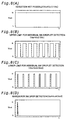
- Figs. 8(A)-8(D) show the relationship between the level of the input voltage Vin to the comparator 214 and the detection operation performed by the photo sensor 200 during light reception.
- Fig. 8(A) shows the results obtained when ink droplet expulsion testing was performed with the level of the input voltage Vin during light reception set to a value Vin1 (Fig. 6) that is higher than the threshold voltage Vth.
- Vin1 Fig. 6
- Vin1' Vin1
- the output voltage Vout supplied from the photo sensor 200 at this voltage Vin1' which is achieved after the increase, is maintained at H level, and therefore the ink droplet Ip cannot be detected.
- Fig. 8(B) shows the results obtained when ink droplet expulsion testing was performed with the input voltage Vin to the comparator 214 during light reception set to a value Vin2 (Fig. 6) that is slightly lower than the threshold voltage Vth.
- Vin2 Fig. 6
- the input voltage Vin2 shown in Fig. 8(B) is close to the threshold voltage Vth, and is the upper limit of the voltage by which the ink droplets may be individually detected. It is possible that, at this upper limit voltage Vin2, the ink droplets may no longer successfully detected if the measurement conditions fluctuate even slightly. Therefore, it is preferred that the appropriate voltage Vcal be set to a voltage lower than this upper limit voltage Vin2.
- Fig. 8(C) shows a situation in which the input voltage Vin to the comparator 214 during light reception is the lower limit voltage Vin3 at which the ink droplets may be individually detected.
- the appropriate voltage Vcal be set to a voltage that is higher than this lower limit voltage Vin3.
- Fig. 8(D) shows a situation in which the input voltage Vin to the comparator 214 during light reception is the detection margin value Vin4.
- the ink droplets may or may not be detected. Therefore, it in not possible to detect them individually.
- Vcal for the input voltage Vin to the comparator 214 is set somewhere between the upper limit voltage Vin2 and the lower limit Vin3, individual ink droplets may be detected in a stable manner regardless of slight fluctuations in the measurement conditions.
- the automatic gain adjustment process described above is preferably carried out immediately before dot dropout inspection is performed and each time dot dropout inspection is carried out. For example, where dot dropout inspection is performed each time the printer performs one pass of main scanning, automatic gain adjustment may be carried out after the one main scanning pass is completed and before dot dropout inspection is performed. Where dot dropout inspection is carried out each time printing of one page is performed, automatic gain adjustment may be carried out immediately before the dot dropout inspection is performed prior to the commencement of printing for one page. Where dot dropout inspection is carried out each time the printer is turned on, automatic gain adjustment may be carried out immediately after the turn-on and before the dot dropout inspection at the turn-on procedure.
- the voltage supplied to the gain adjustment terminal P2 of the photo sensor 200 is adjusted to an appropriate value by means of the D-A converter 202, and therefore, even if there are substantial changes in the environment conditions, dot dropout inspection may be reliably performed.
- the automatic gain adjustment is especially effective for the inspection unit 40 of a light-transmission type because the ink droplet expulsion testing has a fairly low S/N ratio.
- the low S/N ratio means that the appropriate range of the input voltage Vin, between Vin2 and Vin3, is narrow as shown in Fig. 6.
- a preset input voltage Vin may be out of the appropriate range.
- the automatic gain adjustment described above can set the input voltage Vin within an appropriate range under the current conditions.
- Fig. 9 is a block diagram showing the internal construction of the photo-receptor unit in a second embodiment.
- This photo-receptor unit 40b' has, in addition to the photo sensor 200 and the D-A converter 202, a voltage controlled current source (VCC) 204.
- VCC voltage controlled current source
- Two resistors R11 and R12 are serially connected between the gain adjustment terminal P2 of the photo sensor 200 and the D-A converter 202.
- a first current output terminal Ia of the voltage controlled current source 204 is connected to the nodal point between the two resistors R11 and R12 via a second resistor R13.
- Gain adjustment voltage Vg is input to the first voltage input terminal Va of the voltage controlled current source 204.
- the second voltage input terminal Vb and the second current output terminal Ib of the voltage controlled current source 204 are grounded.
- a current corresponding to the gain adjustment voltage Vg is output from the current output terminal Ia of the voltage controlled current source 204, and is supplied to the gain adjustment terminal P2.
- the construction of components other than these is the same as in the first embodiment.
- Automatic gain adjustment may be carried out in this second embodiment in accordance with the sequence shown in Fig. 7 explained above, in the same way as in the first embodiment.
- the current that flows to the gain adjustment terminal P2 of the photo sensor 200 is supplemented by the voltage controlled current source 204, and therefore, the input voltage Vin level is made stable. As a result, more stable gain adjustment may be performed.
- Fig. 10 is a block diagram showing the construction of a variable voltage supply circuit 206 used in the third embodiment.
- This variable voltage supply circuit 206 may replace the D-A converter 202 in the first and second embodiments described above.
- the variable voltage supply circuit 206 comprises a selector 208 and a so-called ladder resistor unit 209 consisting of many resistors.
- the selector 208 selects one or more from among the four output terminals Q1 through Q4 in response to the selection signal SEL supplied from the inspection unit driver 64 (Fig 4) or the system controller 54, and outputs a power source voltage Vcc from the selected output terminal(s).
- This power source voltage Vcc is divided by the ladder resistor unit 209 and is output as a gain adjustment voltage Vg.
- Automatic gain adjustment may be performed in this third embodiment as well, in accordance with the same sequence as that shown in Fig. 7 described above.
- the selection by the selector 208 is alternated so that, instead of making subtractions from the digital input signal Din in Fig. 7, the gain adjustment voltage Vg decreases.
- the gain adjustment voltage Vg since the level of the gain adjustment voltage Vg is set using the D-A converter 202, the gain adjustment voltage Vg may be adjusted within a more precise adjustment range. Therefore, those embodiments have the advantage that the gain adjustment voltage Vg may easily be set to an appropriate calibrated value in response to the changes in the environment conditions.
- the gain adjustment voltage Vg supplied to the photo sensor 200 is reduced, and the threshold voltage Vth was determined by detecting the point at which the level of the output voltage Vout supplied from the photo sensor 200 changes.
- the threshold voltage Vth is sought while the gain adjustment voltage Vg is increased. In other words, generally speaking, for gain adjustment, it is acceptable if the threshold voltage Vth is sought while the gain adjustment voltage Vg is monotonically changed.
Landscapes
- Ink Jet (AREA)
- Particle Formation And Scattering Control In Inkjet Printers (AREA)
- Accessory Devices And Overall Control Thereof (AREA)
Applications Claiming Priority (2)
| Application Number | Priority Date | Filing Date | Title |
|---|---|---|---|
| JP29617499A JP2001113709A (ja) | 1999-10-19 | 1999-10-19 | 印刷装置におけるインク滴の吐出検査装置の調整 |
| JP29617499 | 1999-10-19 |
Publications (2)
| Publication Number | Publication Date |
|---|---|
| EP1093921A1 true EP1093921A1 (de) | 2001-04-25 |
| EP1093921B1 EP1093921B1 (de) | 2004-06-23 |
Family
ID=17830131
Family Applications (1)
| Application Number | Title | Priority Date | Filing Date |
|---|---|---|---|
| EP00122477A Expired - Lifetime EP1093921B1 (de) | 1999-10-19 | 2000-10-13 | Justierung einer Vorrichtung zum Testen des Tintentröpchenausstosses in einem Drucker |
Country Status (5)
| Country | Link |
|---|---|
| US (1) | US6474770B1 (de) |
| EP (1) | EP1093921B1 (de) |
| JP (1) | JP2001113709A (de) |
| AT (1) | ATE269787T1 (de) |
| DE (1) | DE60011729T8 (de) |
Families Citing this family (5)
| Publication number | Priority date | Publication date | Assignee | Title |
|---|---|---|---|---|
| JP3840958B2 (ja) | 2001-11-16 | 2006-11-01 | セイコーエプソン株式会社 | インク吐出判定装置、インクジェットプリンタ、及び、インク吐出判定方法 |
| US6893107B2 (en) | 2003-01-09 | 2005-05-17 | Hewlett-Packard Development Company, L.P. | Method and system for visualizing printed fluids using indicator media |
| US7227756B2 (en) * | 2004-05-27 | 2007-06-05 | Lexmark International, Inc. | Power supply keying arrangement for use with an electrical apparatus |
| JP4678825B2 (ja) * | 2004-12-09 | 2011-04-27 | キヤノン株式会社 | ヘッド基板、記録ヘッド、ヘッドカートリッジ、及びその記録ヘッド或いはヘッドカートリッジを用いた記録装置 |
| JP4165569B2 (ja) | 2006-04-03 | 2008-10-15 | セイコーエプソン株式会社 | 印刷方法 |
Citations (2)
| Publication number | Priority date | Publication date | Assignee | Title |
|---|---|---|---|---|
| US5517217A (en) * | 1992-10-30 | 1996-05-14 | Hewlett-Packard Company | Apparatus for enhancing ink-flow reliability in a thermal-inkjet pen; method for priming and using such a pen |
| EP0744295A1 (de) * | 1995-05-22 | 1996-11-27 | Canon Kabushiki Kaisha | System zur Überwachung eines Tintenausstossausfalles |
Family Cites Families (5)
| Publication number | Priority date | Publication date | Assignee | Title |
|---|---|---|---|---|
| US5434430A (en) * | 1993-04-30 | 1995-07-18 | Hewlett-Packard Company | Drop size detect circuit |
| JP3501599B2 (ja) | 1996-10-23 | 2004-03-02 | キヤノン株式会社 | 記録装置および吐出不良の検出方法 |
| JP3368194B2 (ja) | 1997-12-24 | 2003-01-20 | キヤノン株式会社 | 記録装置 |
| JP3382526B2 (ja) | 1997-12-25 | 2003-03-04 | キヤノン株式会社 | 記録装置及びインク吐出状態検出方法 |
| US6350006B1 (en) * | 1998-11-17 | 2002-02-26 | Pitney Bowes Inc. | Optical ink drop detection apparatus and method for monitoring operation of an ink jet printhead |
-
1999
- 1999-10-19 JP JP29617499A patent/JP2001113709A/ja active Pending
-
2000
- 2000-10-13 EP EP00122477A patent/EP1093921B1/de not_active Expired - Lifetime
- 2000-10-13 DE DE60011729T patent/DE60011729T8/de active Active
- 2000-10-13 AT AT00122477T patent/ATE269787T1/de not_active IP Right Cessation
- 2000-10-18 US US09/690,733 patent/US6474770B1/en not_active Expired - Lifetime
Patent Citations (2)
| Publication number | Priority date | Publication date | Assignee | Title |
|---|---|---|---|---|
| US5517217A (en) * | 1992-10-30 | 1996-05-14 | Hewlett-Packard Company | Apparatus for enhancing ink-flow reliability in a thermal-inkjet pen; method for priming and using such a pen |
| EP0744295A1 (de) * | 1995-05-22 | 1996-11-27 | Canon Kabushiki Kaisha | System zur Überwachung eines Tintenausstossausfalles |
Also Published As
| Publication number | Publication date |
|---|---|
| DE60011729D1 (de) | 2004-07-29 |
| DE60011729T2 (de) | 2005-07-14 |
| EP1093921B1 (de) | 2004-06-23 |
| US6474770B1 (en) | 2002-11-05 |
| DE60011729T8 (de) | 2006-02-23 |
| ATE269787T1 (de) | 2004-07-15 |
| JP2001113709A (ja) | 2001-04-24 |
Similar Documents
| Publication | Publication Date | Title |
|---|---|---|
| EP0709192B1 (de) | Verfahren und Vorrichtung zur Korrektur eines Druckkopfes, mittels dieser Vorrichtung korrigierter Druckkopf und diesen Druckkopf verwendende Druckvorrichtung | |
| US8333452B2 (en) | Image forming apparatus, image forming method and computer-readable storage medium | |
| EP0925929B1 (de) | Druckapparat und Verfahren zur Tintenablagedetektion | |
| US6419341B1 (en) | Method and apparatus for detecting the discharge status of inkjet printheads | |
| KR100788665B1 (ko) | 잉크젯 프린터의 미싱노즐 검출방법 | |
| JP2001018375A (ja) | ノズル列の傾きを考慮した双方向印刷の位置ズレ補正 | |
| US9555620B2 (en) | Printing apparatus and method for adjusting printing position | |
| US6454380B1 (en) | Dot dropout inspection method and printer, and recording medium storing program therefore | |
| US20060125868A1 (en) | Liquid-ejection testing method, liquid-ejection testing device, and computer-readable medium | |
| JP3485015B2 (ja) | ドット抜け検査を行う双方向印刷 | |
| EP1022149A2 (de) | Verfahren und Vorrichtung zur Bereitstellung von Tintenstrahldruckkopfbetreibungsenergie durch optische Bestimmung der Einschaltungsenergie | |
| EP1093921B1 (de) | Justierung einer Vorrichtung zum Testen des Tintentröpchenausstosses in einem Drucker | |
| JP3840958B2 (ja) | インク吐出判定装置、インクジェットプリンタ、及び、インク吐出判定方法 | |
| US6478400B1 (en) | Printing method and printer that effect dot dropout inspection and recording medium prerecorded with program therefore | |
| US7401882B2 (en) | Printing apparatus and method of controlling printing therein | |
| US20060250431A1 (en) | Printing method, printing system, and storage medium having program stored thereon | |
| EP0315206B1 (de) | Punktdrucker | |
| JPH11300944A (ja) | インクジェット記録装置 | |
| US7681979B2 (en) | Inkjet printing system and method capable of automatically calibrating a non-uniform speed of a printhead carriage | |
| JP4292741B2 (ja) | 印刷装置、ドット形成判定方法、コンピュータプログラム、記録媒体、及び、コンピュータシステム | |
| WO2000038927A1 (fr) | Procede d'impression et appareil d'impression pour inspecter des points manquants, et support d'impression pour imprimer ce programme d'inspection | |
| US10864725B2 (en) | Element substrate, printhead and printing apparatus | |
| JP3864692B2 (ja) | 印刷媒体に応じた副走査送り量の補正 | |
| JP4400122B2 (ja) | 印刷装置、及び、コンピュータシステム | |
| JP2002019092A (ja) | 駆動信号生成のためのデータを備えたインクタンク及び当該インクタンクを備えた印刷装置 |
Legal Events
| Date | Code | Title | Description |
|---|---|---|---|
| PUAI | Public reference made under article 153(3) epc to a published international application that has entered the european phase |
Free format text: ORIGINAL CODE: 0009012 |
|
| AK | Designated contracting states |
Kind code of ref document: A1 Designated state(s): AT BE CH CY DE DK ES FI FR GB GR IE IT LI LU MC NL PT SE |
|
| AX | Request for extension of the european patent |
Free format text: AL;LT;LV;MK;RO;SI |
|
| 17P | Request for examination filed |
Effective date: 20010613 |
|
| AKX | Designation fees paid |
Free format text: AT BE CH CY DE DK ES FI FR GB GR IE IT LI LU MC NL PT SE |
|
| GRAP | Despatch of communication of intention to grant a patent |
Free format text: ORIGINAL CODE: EPIDOSNIGR1 |
|
| GRAS | Grant fee paid |
Free format text: ORIGINAL CODE: EPIDOSNIGR3 |
|
| GRAA | (expected) grant |
Free format text: ORIGINAL CODE: 0009210 |
|
| AK | Designated contracting states |
Kind code of ref document: B1 Designated state(s): AT BE CH CY DE DK ES FI FR GB GR IE IT LI LU MC NL PT SE |
|
| PG25 | Lapsed in a contracting state [announced via postgrant information from national office to epo] |
Ref country code: IT Free format text: LAPSE BECAUSE OF FAILURE TO SUBMIT A TRANSLATION OF THE DESCRIPTION OR TO PAY THE FEE WITHIN THE PRESCRIBED TIME-LIMIT;WARNING: LAPSES OF ITALIAN PATENTS WITH EFFECTIVE DATE BEFORE 2007 MAY HAVE OCCURRED AT ANY TIME BEFORE 2007. THE CORRECT EFFECTIVE DATE MAY BE DIFFERENT FROM THE ONE RECORDED. Effective date: 20040623 Ref country code: LI Free format text: LAPSE BECAUSE OF FAILURE TO SUBMIT A TRANSLATION OF THE DESCRIPTION OR TO PAY THE FEE WITHIN THE PRESCRIBED TIME-LIMIT Effective date: 20040623 Ref country code: CY Free format text: LAPSE BECAUSE OF FAILURE TO SUBMIT A TRANSLATION OF THE DESCRIPTION OR TO PAY THE FEE WITHIN THE PRESCRIBED TIME-LIMIT Effective date: 20040623 Ref country code: FI Free format text: LAPSE BECAUSE OF FAILURE TO SUBMIT A TRANSLATION OF THE DESCRIPTION OR TO PAY THE FEE WITHIN THE PRESCRIBED TIME-LIMIT Effective date: 20040623 Ref country code: BE Free format text: LAPSE BECAUSE OF FAILURE TO SUBMIT A TRANSLATION OF THE DESCRIPTION OR TO PAY THE FEE WITHIN THE PRESCRIBED TIME-LIMIT Effective date: 20040623 Ref country code: CH Free format text: LAPSE BECAUSE OF FAILURE TO SUBMIT A TRANSLATION OF THE DESCRIPTION OR TO PAY THE FEE WITHIN THE PRESCRIBED TIME-LIMIT Effective date: 20040623 Ref country code: NL Free format text: LAPSE BECAUSE OF FAILURE TO SUBMIT A TRANSLATION OF THE DESCRIPTION OR TO PAY THE FEE WITHIN THE PRESCRIBED TIME-LIMIT Effective date: 20040623 Ref country code: AT Free format text: LAPSE BECAUSE OF FAILURE TO SUBMIT A TRANSLATION OF THE DESCRIPTION OR TO PAY THE FEE WITHIN THE PRESCRIBED TIME-LIMIT Effective date: 20040623 |
|
| RAP1 | Party data changed (applicant data changed or rights of an application transferred) |
Owner name: SEIKO EPSON CORPORATION |
|
| REG | Reference to a national code |
Ref country code: GB Ref legal event code: FG4D |
|
| REG | Reference to a national code |
Ref country code: CH Ref legal event code: EP |
|
| REG | Reference to a national code |
Ref country code: IE Ref legal event code: FG4D |
|
| REF | Corresponds to: |
Ref document number: 60011729 Country of ref document: DE Date of ref document: 20040729 Kind code of ref document: P |
|
| PG25 | Lapsed in a contracting state [announced via postgrant information from national office to epo] |
Ref country code: SE Free format text: LAPSE BECAUSE OF FAILURE TO SUBMIT A TRANSLATION OF THE DESCRIPTION OR TO PAY THE FEE WITHIN THE PRESCRIBED TIME-LIMIT Effective date: 20040923 Ref country code: GR Free format text: LAPSE BECAUSE OF FAILURE TO SUBMIT A TRANSLATION OF THE DESCRIPTION OR TO PAY THE FEE WITHIN THE PRESCRIBED TIME-LIMIT Effective date: 20040923 Ref country code: DK Free format text: LAPSE BECAUSE OF FAILURE TO SUBMIT A TRANSLATION OF THE DESCRIPTION OR TO PAY THE FEE WITHIN THE PRESCRIBED TIME-LIMIT Effective date: 20040923 |
|
| PG25 | Lapsed in a contracting state [announced via postgrant information from national office to epo] |
Ref country code: ES Free format text: LAPSE BECAUSE OF FAILURE TO SUBMIT A TRANSLATION OF THE DESCRIPTION OR TO PAY THE FEE WITHIN THE PRESCRIBED TIME-LIMIT Effective date: 20041004 |
|
| PG25 | Lapsed in a contracting state [announced via postgrant information from national office to epo] |
Ref country code: LU Free format text: LAPSE BECAUSE OF NON-PAYMENT OF DUE FEES Effective date: 20041013 Ref country code: IE Free format text: LAPSE BECAUSE OF NON-PAYMENT OF DUE FEES Effective date: 20041013 |
|
| PG25 | Lapsed in a contracting state [announced via postgrant information from national office to epo] |
Ref country code: MC Free format text: LAPSE BECAUSE OF NON-PAYMENT OF DUE FEES Effective date: 20041031 |
|
| NLV1 | Nl: lapsed or annulled due to failure to fulfill the requirements of art. 29p and 29m of the patents act | ||
| REG | Reference to a national code |
Ref country code: CH Ref legal event code: PL |
|
| ET | Fr: translation filed | ||
| PLBE | No opposition filed within time limit |
Free format text: ORIGINAL CODE: 0009261 |
|
| STAA | Information on the status of an ep patent application or granted ep patent |
Free format text: STATUS: NO OPPOSITION FILED WITHIN TIME LIMIT |
|
| 26N | No opposition filed |
Effective date: 20050324 |
|
| REG | Reference to a national code |
Ref country code: IE Ref legal event code: MM4A |
|
| PG25 | Lapsed in a contracting state [announced via postgrant information from national office to epo] |
Ref country code: PT Free format text: LAPSE BECAUSE OF NON-PAYMENT OF DUE FEES Effective date: 20041123 |
|
| REG | Reference to a national code |
Ref country code: FR Ref legal event code: PLFP Year of fee payment: 16 |
|
| REG | Reference to a national code |
Ref country code: FR Ref legal event code: PLFP Year of fee payment: 17 |
|
| REG | Reference to a national code |
Ref country code: FR Ref legal event code: PLFP Year of fee payment: 18 |
|
| PGFP | Annual fee paid to national office [announced via postgrant information from national office to epo] |
Ref country code: FR Payment date: 20170918 Year of fee payment: 18 |
|
| PGFP | Annual fee paid to national office [announced via postgrant information from national office to epo] |
Ref country code: DE Payment date: 20171011 Year of fee payment: 18 |
|
| PGFP | Annual fee paid to national office [announced via postgrant information from national office to epo] |
Ref country code: GB Payment date: 20171011 Year of fee payment: 18 |
|
| REG | Reference to a national code |
Ref country code: DE Ref legal event code: R119 Ref document number: 60011729 Country of ref document: DE |
|
| GBPC | Gb: european patent ceased through non-payment of renewal fee |
Effective date: 20181013 |
|
| PG25 | Lapsed in a contracting state [announced via postgrant information from national office to epo] |
Ref country code: DE Free format text: LAPSE BECAUSE OF NON-PAYMENT OF DUE FEES Effective date: 20190501 |
|
| PG25 | Lapsed in a contracting state [announced via postgrant information from national office to epo] |
Ref country code: FR Free format text: LAPSE BECAUSE OF NON-PAYMENT OF DUE FEES Effective date: 20181031 |
|
| PG25 | Lapsed in a contracting state [announced via postgrant information from national office to epo] |
Ref country code: GB Free format text: LAPSE BECAUSE OF NON-PAYMENT OF DUE FEES Effective date: 20181013 |