EP1091376A2 - Elektrischer Kipptastenschalter - Google Patents
Elektrischer Kipptastenschalter Download PDFInfo
- Publication number
- EP1091376A2 EP1091376A2 EP00120697A EP00120697A EP1091376A2 EP 1091376 A2 EP1091376 A2 EP 1091376A2 EP 00120697 A EP00120697 A EP 00120697A EP 00120697 A EP00120697 A EP 00120697A EP 1091376 A2 EP1091376 A2 EP 1091376A2
- Authority
- EP
- European Patent Office
- Prior art keywords
- button
- actuator
- toggle switch
- switch according
- circuit board
- Prior art date
- Legal status (The legal status is an assumption and is not a legal conclusion. Google has not performed a legal analysis and makes no representation as to the accuracy of the status listed.)
- Granted
Links
Images


Classifications
-
- H—ELECTRICITY
- H01—ELECTRIC ELEMENTS
- H01H—ELECTRIC SWITCHES; RELAYS; SELECTORS; EMERGENCY PROTECTIVE DEVICES
- H01H21/00—Switches operated by an operating part in the form of a pivotable member acted upon directly by a solid body, e.g. by a hand
- H01H21/02—Details
- H01H21/18—Movable parts; Contacts mounted thereon
- H01H21/22—Operating parts, e.g. handle
- H01H21/24—Operating parts, e.g. handle biased to return to normal position upon removal of operating force
-
- H—ELECTRICITY
- H01—ELECTRIC ELEMENTS
- H01H—ELECTRIC SWITCHES; RELAYS; SELECTORS; EMERGENCY PROTECTIVE DEVICES
- H01H21/00—Switches operated by an operating part in the form of a pivotable member acted upon directly by a solid body, e.g. by a hand
- H01H21/02—Details
- H01H21/18—Movable parts; Contacts mounted thereon
- H01H21/36—Driving mechanisms
-
- H—ELECTRICITY
- H01—ELECTRIC ELEMENTS
- H01H—ELECTRIC SWITCHES; RELAYS; SELECTORS; EMERGENCY PROTECTIVE DEVICES
- H01H1/00—Contacts
- H01H1/58—Electric connections to or between contacts; Terminals
- H01H1/5805—Connections to printed circuits
Definitions
- the invention relates to an electrical toggle switch with a button mounted on a housing, the one Actuator assigned to act on a switching element is.
- an electrical key switch is known the housing with a switching element at least one automatically resetting and off-center stored button is provided.
- an actuator is formed on the button, that interacts with an assigned snap disc, which both resets the button and is used to connect current paths on a printed circuit board.
- a disadvantage here is that the limited Travel of the snap disk is only a relatively short one Switching path of the button is realizable and in the event of an overstroke the button the circuit board due to an excessive application force can be damaged.
- DE-U-76 34 027 discloses a momentary switch, whose electrical contacts via a one-sided Button with an associated, slidably mounted Actuation approach can be acted upon. This is the way of actuation the key from the switching path of the assigned contacts dependent. There is also a dependency between the Contacts and the counterforce that the actuator of the actuating force the key opposite.
- DE-A-197 26 529 shows an electrical key switch with a housing in which a switching elements Contact unit is arranged, and with at least an automatically resetting and off-center Key with an actuator acting on the switching elements, which is molded onto the button.
- This is the Contact unit resiliently mounted in the housing and against excessive Force applied by the actuator to the switching elements compliant, being between the contact unit and the base the housing a spring unit is arranged.
- a counterforce the actuating force of the button is activated by a compression spring generated, which is between the actuator or the button and supports the contact unit. Due to the arrangement of the Spring unit between the contact unit and the base of the Housing this push button switch has a relatively complicated Building on.
- the object is achieved in that the actuator is designed as a leaf spring, one end of which is on the housing side and their other free, with the Switching element cooperating end under tension on the Button is present.
- the operating force of the button depending on the spring action of the actuator, which at the same time causes the key to be reset after it has been acted on and holds the key in its original position.
- the actuator provides a desired counterforce to the actuating force the button is available, creating a corresponding tactile Switching sensation is generated.
- the fact that the free end of the actuator designed as a leaf spring on the switching element acts, the switching element is in front of an overstroke button-related overload, when the button is pressed can be stamped, protected because the leaf spring in the elastic range is compliant.
- the switching element is preferably designed as a microswitch and arranged on a perpendicular to a bottom of the housing PCB attached, with the PCB in the inside of the hollow button extends.
- the toggle switch a very compact structure with more reliable How it works.
- the PCB should also be fixed exactly to the housing held between guide lugs of the housing.
- the guide lugs are integrally formed on the housing and are manufactured together with this in the injection molding process.
- the key is expediently by means of an opposing one and spaced apart mounting brackets, which are in the Stretch inside the button, stored.
- the bearing brackets are also integrally formed on the housing and act as they are inside the button, optically not annoying.
- the button is molded onto an attachment on which the free end of the actuator is present.
- the approach represents an exact transfer the actuating force acting on the button on the actuator and thus also on the switching element.
- the actuator is preferably essentially U-shaped, one leg attached to the circuit board is the other leg that acts on the microswitch is supported on the base of the button and the leg connecting web is inclined in the direction of the microswitch.
- the distance between the parallel legs of the U shape is on the one hand to the height of the microswitch and on the other adapted to the actuation path of the button.
- the inclination of the Steges essentially influences the counterforce that the actuator opposed to the actuating force of the button.
- the free end of the actuator is expediently provided with a Angle to the linear contact of the microswitch Mistake. Furthermore, the free one preferably extends End of the actuator beyond the approach of the key. With one Overpressure of the button bends the one assigned to the microswitch Leg in the support area of the approach of the button through, which is why there is a risk of damage to the microswitch and the associated circuit board is relatively low.
- the actuator is preferred in relatively large quantities punched in one piece and shaped accordingly.
- This The actuator can be manufactured using a progressive tool with relatively small tolerances.
- toggle switches of this type are rarely used used alone are preferred. This measure reduces the Installation effort of several toggle switches considerably, since only the connection contacts of the common circuit board must be electrically connected. Conveniently the keys are parallel and spaced apart stored on the housing. This makes tactile easier Detection of the individual keys of the toggle switch is guaranteed.
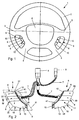
- a steering wheel 1 comprises a steering wheel rim 2, which spokes 3 is connected to the steering wheel bowl 4. On each Side of the steering wheel 1 is between adjacent spokes 3 one each consisting of several toggle switches 6 Switch unit 5 inserted into the steering wheel bowl 4. The Switch units 5 are connected via connecting lines 7 common connectors 8 for coupling the toggle switch 6 in connection with an electrical system of a motor vehicle.
- Each toggle switch 6 is common to one Housing 9 stored key 10 provided on the operator facing side a back-lit symbol 11 carries and the end facing away from the operator as Actuating surface 18 is formed.
- the button 10 has the housing 9 opposite to each other spaced bearing tabs 12, which are located inside the hollow button 10 extend, the bearing tabs 12 on their free ends in corresponding holes 14 of the key Wear 10 engaging pins 13.
- an aperture 15 is provided below the 10 buttons, which is formed by means of a molded web 16 inserted into corresponding guide grooves 17 of the housing 9 becomes.
- the housing 9 with guide lugs 19 provided for holding a circuit board 20 which in Area of the button 10 of the middle toggle switch 6 of one on the top and in the area of each key 9 the toggle switch 6 is held by an underside stop 21.
- the stops 21 prevent deflection of the circuit board 20 in one direction or another.
- the leadership approaches 19 each have a groove 22 for receiving the circuit board 20 on.
- the circuit board 20 is perpendicular to a floor 41 of the housing 9 arranged and carries in the area of each key 10th a switching element designed as a microswitch 23 and an actuator 24 assigned to the microswitch 23, wherein the circuit board 20 with the microswitch 23 and the area 24 supporting the actuator 24 into the inside of the button 10 extends.
- the actuator 24 designed as a leaf spring 40 is essentially U-shaped, one leg 26 on the circuit board 20 is attached, the other, the microswitch 23rd acting leg 27 under tension on a Approach 28 supports the button 10 and the legs 26, 27th connecting web 29 inclined in the direction of the microswitch 23 is.
- the leg 26 fixed to the printed circuit board 20 Actuator 24 comprises two spaced apart, via one Flange 30 interconnected arms 31 on which angled Extensions 32 for determining the actuator 24 in corresponding Bores of the circuit board 20 are formed.
- the free end of the leg 27 of the actuator 24 is one Angle 33 for linear contact of the microswitch 23 provided and extends over the approach 28th button 10.
- the switch units 5 shown are used for remote control a not shown radio of a motor vehicle, a toggle switch 6 as a memory interrogation switch 36 of the radio, two toggle switches 6 as station search switch 37 to search for a radio station in different Directions, a toggle switch 6 as a switch 38 for switching between radio and cassette operation and two toggle switches 6 as a volume switch 39 for regulating the Volume of the radio are provided.
- the operator of the radio can therefore control all functions without his hands need to take off the steering wheel 1 by using the appropriate Fingers of the right or left hand the assigned Actuating surfaces 18 on the button 10 of the toggle switch 6 acted upon. To facilitate easier tactile recognition of the individual To ensure buttons 10, they are spaced apart mounted on the common housing 9.
Landscapes
- Push-Button Switches (AREA)
- Rotary Switch, Piano Key Switch, And Lever Switch (AREA)
Abstract
Description
- Fig.1
- eine Ansicht auf ein Lenkrad eines Kraftfahrzeuges mit erfindungsgemäßen elektrischen Kipptastschaltern,
- Fig.2
- eine perspektivische Ansicht auf aus elektrischen Kipptastschaltern zusammengesetzte Schaltereinheiten,
- Fig.3
- eine Explosionsdarstellung der Einzelheit III nach Fig. 2,
- Fig.4
- eine vergrößerte Schnittansicht durch den Kipptastschalter entlang der Linie IV-IV nach Fig. 2 und
- Fig.5
- eine vergrößerte Darstellung der Einzelheit V nach Fig. 3.
- 1.
- Lenkrad
- 2.
- Lenkradkranz
- 3.
- Speiche
- 4.
- Lenkradschüssel
- 5.
- Schaltereinheit
- 6.
- Kipptastschalter
- 7.
- Verbindungsleitungen
- 8.
- Anschlußstecker
- 9.
- Gehäuse
- 10.
- Taste
- 11.
- Symbol
- 12.
- Lagerlasche
- 13.
- Zapfen
- 14.
- Bohrung
- 15.
- Blende
- 16.
- Steg
- 17.
- Führungsnut
- 18.
- Betätigungsfläche
- 19.
- Führungsansatz
- 20.
- Leiterplatte
- 21.
- Anschlag
- 22.
- Nut
- 23.
- Mikroschalter
- 24.
- Betätiger
- 25.
- Bereich
- 26.
- Schenkel
- 27.
- Schenkel
- 28.
- Ansatz
- 29.
- Steg
- 30.
- Flansch
- 31.
- Arm
- 32.
- Fortsatz
- 33.
- Abwinklung
- 34.
- Anschlag
- 35.
- Öffnung
- 36.
- Speicherabfrage-Schalter
- 37.
- Sendersuchlauf-Schalter
- 38.
- Umschalter
- 39.
- Lautstärke-Schalter
- 40.
- Blattfeder
- 41.
- Boden
Claims (13)
- Elektrischer Kipptastschalter (6) mit einer an einem Gehäuse (9) gelagerten Taste (10), der ein Betätiger (24) zur Beaufschlagung eines Schaltelementes zugeordnet ist, dadurch gekennzeichnet, daß der Betätiger (24) als Blattfeder (40) ausgebildet ist, deren eines Ende gehäuseseitig festgelegt ist und deren anderes freies, mit dem Schaltelement zusammenwirkendes Ende unter Vorspannung an der Taste (10) anliegt.
- Kipptastschalter nach Anspruch 1, dadurch gekennzeichnet, daß das Schaltelement als Mikroschalter (23) ausgebildet und auf einer senkrecht zu einem Boden (41) des Gehäuses (9) angeordneten Leiterplatte (20) befestigt ist, wobei sich die Leiterplatte (22) in das Innere der hohlen Taste (10) erstreckt.
- Kipptastschalter nach den Ansprüchen 1 und 2, dadurch gekennzeichnet, daß die Leiterplatte (20) zwischen Führungsansätzen (19) des Gehäuses (9) gehalten ist.
- Kipptastschalter nach Anspruch 1, dadurch gekennzeichnet, daß die Taste (10) mittels gegenüberliegender sowie zueinander beabstandeter Lagerlaschen (12), die sich in das Innere der Taste (10) erstrecken, gelagert ist.
- Kipptastschalter nach Anspruch 1 oder 4, dadurch gekennzeichnet, daß an der Taste (10) ein Ansatz (28) angeformt ist, an dem das freie Ende des Betä-tigers (24) anliegt.
- Kipptastschalter nach einem der Ansprüche 1 bis 5, dadurch gekennzeichnet, daß der Betätiger (24) im wesentlichen U-förmig ausgebildet ist, wobei der eine Schenkel (26) an der Leiterplatte (20) befestigt ist, der andere, den Mikroschalter (23) beaufschlagende Schenkel (27) sich an dem Ansatz (28) der Taste (10) abstützt und der die Schenkel (26, 27) verbindende Steg (29) in Richtung des Mikroschalters (23) geneigt ist.
- Kipptastschalter nach Anspruch 6, dadurch gekennzeichnet, daß der an der Leiterplatte (20) festgelegte Schenkel (26) zwei zueinander beabstandete, über einen Flansch (30) verbundene Arme (31) aufweist, wobei von dem Flansch (30) der Steg (29) abgeht.
- Kipptastschalter nach Anspruch 7, dadurch gekennzeichnet, daß an den Armen (31) abgewinkelte Fortsätze (32) zur Festlegung des Betätigers (24) in korrespondierenden Bohrungen der Leiterplatte (20) angeformt sind.
- Kipptastschalter nach einem der Ansprüche 1 bis 8, dadurch gekennzeichnet, daß das freie Ende des Betätigers (24) mit einer Abwinklung (33) zur linienförmigen Berührung des Mikroschalters (28) versehen ist.
- Kipptastschalter nach einem der Ansprüche 1 bis 9, dadurch gekennzeichnet, daß sich das freie Ende des Betätigers (24) über den Ansatz (28) der Taste (10) hinauserstreckt.
- Kipptastschalter nach einem der Ansprüche 1 bis 10, dadurch gekennzeichnet, daß der Betätiger (24) einstückig gestanzt und entsprechend umgeformt ist.
- Kipptastschalter nach einem der Ansprüche 1 bis 11, dadurch gekennzeichnet, daß an der Leiterplatte (20) mehrere Kipptastschalter (6) nebeneinander angeordnet sind.
- Kipptastschalter nach Anspruch 12, dadurch gekennzeichnet, daß die Tasten (10) parallel sowie zueinander beabstandet an dem Gehäuse (9) gelagert sind.
Applications Claiming Priority (2)
| Application Number | Priority Date | Filing Date | Title |
|---|---|---|---|
| DE19948723 | 1999-10-09 | ||
| DE19948723A DE19948723A1 (de) | 1999-10-09 | 1999-10-09 | Elektrischer Kipptastschalter |
Publications (3)
| Publication Number | Publication Date |
|---|---|
| EP1091376A2 true EP1091376A2 (de) | 2001-04-11 |
| EP1091376A3 EP1091376A3 (de) | 2003-04-02 |
| EP1091376B1 EP1091376B1 (de) | 2004-12-22 |
Family
ID=7925096
Family Applications (1)
| Application Number | Title | Priority Date | Filing Date |
|---|---|---|---|
| EP00120697A Expired - Lifetime EP1091376B1 (de) | 1999-10-09 | 2000-09-22 | Elektrischer Kipptastenschalter |
Country Status (2)
| Country | Link |
|---|---|
| EP (1) | EP1091376B1 (de) |
| DE (2) | DE19948723A1 (de) |
Cited By (1)
| Publication number | Priority date | Publication date | Assignee | Title |
|---|---|---|---|---|
| EP1538029A1 (de) * | 2003-11-17 | 2005-06-08 | METHODE ELECTRONICS, Inc. | Schwimmende Kontaktanordnung für ein Lenkrad |
Families Citing this family (2)
| Publication number | Priority date | Publication date | Assignee | Title |
|---|---|---|---|---|
| DE102015225310B3 (de) | 2015-12-15 | 2017-03-30 | Volkswagen Aktiengesellschaft | Vorrichtung zum Erfassen von Eingaben eines Nutzers in einem Fahrzeug und Fahrzeug |
| DE102016112277A1 (de) * | 2016-07-05 | 2018-01-11 | Trw Automotive Electronics & Components Gmbh | Bedienbaugruppe für ein Kraftfahrzeug |
Family Cites Families (6)
| Publication number | Priority date | Publication date | Assignee | Title |
|---|---|---|---|---|
| US4496803A (en) * | 1983-05-04 | 1985-01-29 | Key Concepts, Incorporated | Data entry switch |
| JPH073547Y2 (ja) * | 1988-07-25 | 1995-01-30 | アルプス電気株式会社 | 押釦スイツチ |
| DE68927888T2 (de) * | 1989-07-05 | 1997-08-14 | Idec Izumi Corp | Schalter mit Anzeiger |
| JP3404956B2 (ja) * | 1995-01-31 | 2003-05-12 | 松下電器産業株式会社 | プッシュスイッチ |
| EP0845718B1 (de) * | 1996-12-02 | 2000-05-10 | Eta SA Fabriques d'Ebauches | Elektrische Schaltvorrichtung auf einer gedruckten Schaltung und Uhr, die eine solche Vorrichtung enthält |
| DE19726529C2 (de) * | 1997-06-23 | 2001-07-05 | Eaton Controls Gmbh | Elektrischer Tastschalter |
-
1999
- 1999-10-09 DE DE19948723A patent/DE19948723A1/de not_active Withdrawn
-
2000
- 2000-09-22 EP EP00120697A patent/EP1091376B1/de not_active Expired - Lifetime
- 2000-09-22 DE DE50009006T patent/DE50009006D1/de not_active Expired - Fee Related
Cited By (2)
| Publication number | Priority date | Publication date | Assignee | Title |
|---|---|---|---|---|
| EP1538029A1 (de) * | 2003-11-17 | 2005-06-08 | METHODE ELECTRONICS, Inc. | Schwimmende Kontaktanordnung für ein Lenkrad |
| US7029284B2 (en) | 2003-11-17 | 2006-04-18 | Methode Electronics, Inc. | Floating contact assembly for a steering wheel |
Also Published As
| Publication number | Publication date |
|---|---|
| DE50009006D1 (de) | 2005-01-27 |
| DE19948723A1 (de) | 2001-04-12 |
| EP1091376A3 (de) | 2003-04-02 |
| EP1091376B1 (de) | 2004-12-22 |
Similar Documents
| Publication | Publication Date | Title |
|---|---|---|
| EP0553694B1 (de) | Elektrischer Schalter | |
| DE19734997C2 (de) | Druckknopf-Schalter mit scherenartigen Armelementen | |
| DE19853438A1 (de) | Multidirektionale Tastschalteranordnung | |
| DE3229280C2 (de) | ||
| DE19829811C2 (de) | Mehrrichtungs-Eingabevorrichtung | |
| EP0953480A2 (de) | Lenkradschalter für ein Kraftfahrzeug | |
| EP1557852B1 (de) | Fahrzeuglenkrad | |
| DE2337904A1 (de) | Eingabe-taste | |
| WO1998010453A1 (de) | Elektrische vorrichtung zum verdunsten von wirkstoffen | |
| EP0887819B1 (de) | Elektrischer Tastschalter | |
| DE10241048A1 (de) | Schalteinrichtung für eine Fahrzeughupe | |
| EP1091376B1 (de) | Elektrischer Kipptastenschalter | |
| EP0884744B1 (de) | Monostabiles Schaltgerät | |
| EP1247286B1 (de) | Elektrischer schalter | |
| DE3033808A1 (de) | Tastschalter | |
| DE2559861B1 (de) | Verriegelbarer Drucktastenschalter | |
| EP3686909A1 (de) | Elektroinstallationsgerät mit sockelaufsatz | |
| DE4340276A1 (de) | Mehrstufiger Handschalter | |
| EP0634764A1 (de) | Tastmodul zum Schalten | |
| EP1808877B1 (de) | Elektrischer Mikro-Schalter | |
| EP1240655A1 (de) | Elektrischer schalter | |
| DE29520909U1 (de) | Elektrisches Schaltgerät | |
| DE19616713C1 (de) | Schalteranordnung für die Betätigung eines Mikroschalters durch einen Stößel | |
| DE2007265C3 (de) | Elektrischer Schalter mit einem wenigstens eine Lampe aufweisenden Betätigungsglied | |
| EP1151447B2 (de) | Kontaktfeder-einheit für einen elektrischen schalter |
Legal Events
| Date | Code | Title | Description |
|---|---|---|---|
| PUAI | Public reference made under article 153(3) epc to a published international application that has entered the european phase |
Free format text: ORIGINAL CODE: 0009012 |
|
| AK | Designated contracting states |
Kind code of ref document: A2 Designated state(s): AT BE CH CY DE DK ES FI FR GB GR IE IT LI LU MC NL PT SE |
|
| AX | Request for extension of the european patent |
Free format text: AL;LT;LV;MK;RO;SI |
|
| RAP1 | Party data changed (applicant data changed or rights of an application transferred) |
Owner name: DELPHI TECHNOLOGIES INC. |
|
| PUAL | Search report despatched |
Free format text: ORIGINAL CODE: 0009013 |
|
| AK | Designated contracting states |
Kind code of ref document: A3 Designated state(s): AT BE CH CY DE DK ES FI FR GB GR IE IT LI LU MC NL PT SE Designated state(s): AT BE CH CY DE DK ES FI FR GB GR IE IT LI LU MC NL PT SE |
|
| AX | Request for extension of the european patent |
Extension state: AL LT LV MK RO SI |
|
| 17P | Request for examination filed |
Effective date: 20030807 |
|
| 17Q | First examination report despatched |
Effective date: 20031117 |
|
| AKX | Designation fees paid |
Designated state(s): DE FR |
|
| GRAP | Despatch of communication of intention to grant a patent |
Free format text: ORIGINAL CODE: EPIDOSNIGR1 |
|
| GRAS | Grant fee paid |
Free format text: ORIGINAL CODE: EPIDOSNIGR3 |
|
| GRAA | (expected) grant |
Free format text: ORIGINAL CODE: 0009210 |
|
| AK | Designated contracting states |
Kind code of ref document: B1 Designated state(s): DE FR |
|
| REG | Reference to a national code |
Ref country code: IE Ref legal event code: FG4D Free format text: GERMAN |
|
| REF | Corresponds to: |
Ref document number: 50009006 Country of ref document: DE Date of ref document: 20050127 Kind code of ref document: P |
|
| PLBE | No opposition filed within time limit |
Free format text: ORIGINAL CODE: 0009261 |
|
| STAA | Information on the status of an ep patent application or granted ep patent |
Free format text: STATUS: NO OPPOSITION FILED WITHIN TIME LIMIT |
|
| 26N | No opposition filed |
Effective date: 20050923 |
|
| ET | Fr: translation filed | ||
| PGFP | Annual fee paid to national office [announced via postgrant information from national office to epo] |
Ref country code: FR Payment date: 20080915 Year of fee payment: 9 |
|
| PGFP | Annual fee paid to national office [announced via postgrant information from national office to epo] |
Ref country code: DE Payment date: 20081002 Year of fee payment: 9 |
|
| REG | Reference to a national code |
Ref country code: FR Ref legal event code: ST Effective date: 20100531 |
|
| PG25 | Lapsed in a contracting state [announced via postgrant information from national office to epo] |
Ref country code: FR Free format text: LAPSE BECAUSE OF NON-PAYMENT OF DUE FEES Effective date: 20090930 Ref country code: DE Free format text: LAPSE BECAUSE OF NON-PAYMENT OF DUE FEES Effective date: 20100401 |