EP1091117B1 - Injecteur de carburant - Google Patents
Injecteur de carburant Download PDFInfo
- Publication number
- EP1091117B1 EP1091117B1 EP20000308802 EP00308802A EP1091117B1 EP 1091117 B1 EP1091117 B1 EP 1091117B1 EP 20000308802 EP20000308802 EP 20000308802 EP 00308802 A EP00308802 A EP 00308802A EP 1091117 B1 EP1091117 B1 EP 1091117B1
- Authority
- EP
- European Patent Office
- Prior art keywords
- valve needle
- region
- seating
- fuel
- outer valve
- Prior art date
- Legal status (The legal status is an assumption and is not a legal conclusion. Google has not performed a legal analysis and makes no representation as to the accuracy of the status listed.)
- Expired - Lifetime
Links
Images


Classifications
-
- F—MECHANICAL ENGINEERING; LIGHTING; HEATING; WEAPONS; BLASTING
- F02—COMBUSTION ENGINES; HOT-GAS OR COMBUSTION-PRODUCT ENGINE PLANTS
- F02M—SUPPLYING COMBUSTION ENGINES IN GENERAL WITH COMBUSTIBLE MIXTURES OR CONSTITUENTS THEREOF
- F02M61/00—Fuel-injectors not provided for in groups F02M39/00 - F02M57/00 or F02M67/00
- F02M61/16—Details not provided for in, or of interest apart from, the apparatus of groups F02M61/02 - F02M61/14
- F02M61/18—Injection nozzles, e.g. having valve seats; Details of valve member seated ends, not otherwise provided for
- F02M61/1806—Injection nozzles, e.g. having valve seats; Details of valve member seated ends, not otherwise provided for characterised by the arrangement of discharge orifices, e.g. orientation or size
- F02M61/182—Discharge orifices being situated in different transversal planes with respect to valve member direction of movement
-
- F—MECHANICAL ENGINEERING; LIGHTING; HEATING; WEAPONS; BLASTING
- F02—COMBUSTION ENGINES; HOT-GAS OR COMBUSTION-PRODUCT ENGINE PLANTS
- F02M—SUPPLYING COMBUSTION ENGINES IN GENERAL WITH COMBUSTIBLE MIXTURES OR CONSTITUENTS THEREOF
- F02M45/00—Fuel-injection apparatus characterised by having a cyclic delivery of specific time/pressure or time/quantity relationship
- F02M45/02—Fuel-injection apparatus characterised by having a cyclic delivery of specific time/pressure or time/quantity relationship with each cyclic delivery being separated into two or more parts
- F02M45/04—Fuel-injection apparatus characterised by having a cyclic delivery of specific time/pressure or time/quantity relationship with each cyclic delivery being separated into two or more parts with a small initial part, e.g. initial part for partial load and initial and main part for full load
- F02M45/08—Injectors peculiar thereto
- F02M45/086—Having more than one injection-valve controlling discharge orifices
-
- F—MECHANICAL ENGINEERING; LIGHTING; HEATING; WEAPONS; BLASTING
- F02—COMBUSTION ENGINES; HOT-GAS OR COMBUSTION-PRODUCT ENGINE PLANTS
- F02M—SUPPLYING COMBUSTION ENGINES IN GENERAL WITH COMBUSTIBLE MIXTURES OR CONSTITUENTS THEREOF
- F02M47/00—Fuel-injection apparatus operated cyclically with fuel-injection valves actuated by fluid pressure
- F02M47/02—Fuel-injection apparatus operated cyclically with fuel-injection valves actuated by fluid pressure of accumulator-injector type, i.e. having fuel pressure of accumulator tending to open, and fuel pressure in other chamber tending to close, injection valves and having means for periodically releasing that closing pressure
- F02M47/027—Electrically actuated valves draining the chamber to release the closing pressure
-
- F—MECHANICAL ENGINEERING; LIGHTING; HEATING; WEAPONS; BLASTING
- F02—COMBUSTION ENGINES; HOT-GAS OR COMBUSTION-PRODUCT ENGINE PLANTS
- F02M—SUPPLYING COMBUSTION ENGINES IN GENERAL WITH COMBUSTIBLE MIXTURES OR CONSTITUENTS THEREOF
- F02M55/00—Fuel-injection apparatus characterised by their fuel conduits or their venting means; Arrangements of conduits between fuel tank and pump F02M37/00
- F02M55/002—Arrangement of leakage or drain conduits in or from injectors
-
- F—MECHANICAL ENGINEERING; LIGHTING; HEATING; WEAPONS; BLASTING
- F02—COMBUSTION ENGINES; HOT-GAS OR COMBUSTION-PRODUCT ENGINE PLANTS
- F02M—SUPPLYING COMBUSTION ENGINES IN GENERAL WITH COMBUSTIBLE MIXTURES OR CONSTITUENTS THEREOF
- F02M61/00—Fuel-injectors not provided for in groups F02M39/00 - F02M57/00 or F02M67/00
- F02M61/04—Fuel-injectors not provided for in groups F02M39/00 - F02M57/00 or F02M67/00 having valves, e.g. having a plurality of valves in series
- F02M61/06—Fuel-injectors not provided for in groups F02M39/00 - F02M57/00 or F02M67/00 having valves, e.g. having a plurality of valves in series the valves being furnished at seated ends with pintle or plug shaped extensions
-
- F—MECHANICAL ENGINEERING; LIGHTING; HEATING; WEAPONS; BLASTING
- F02—COMBUSTION ENGINES; HOT-GAS OR COMBUSTION-PRODUCT ENGINE PLANTS
- F02M—SUPPLYING COMBUSTION ENGINES IN GENERAL WITH COMBUSTIBLE MIXTURES OR CONSTITUENTS THEREOF
- F02M61/00—Fuel-injectors not provided for in groups F02M39/00 - F02M57/00 or F02M67/00
- F02M61/04—Fuel-injectors not provided for in groups F02M39/00 - F02M57/00 or F02M67/00 having valves, e.g. having a plurality of valves in series
- F02M61/10—Other injectors with elongated valve bodies, i.e. of needle-valve type
- F02M61/12—Other injectors with elongated valve bodies, i.e. of needle-valve type characterised by the provision of guiding or centring means for valve bodies
-
- F—MECHANICAL ENGINEERING; LIGHTING; HEATING; WEAPONS; BLASTING
- F02—COMBUSTION ENGINES; HOT-GAS OR COMBUSTION-PRODUCT ENGINE PLANTS
- F02M—SUPPLYING COMBUSTION ENGINES IN GENERAL WITH COMBUSTIBLE MIXTURES OR CONSTITUENTS THEREOF
- F02M61/00—Fuel-injectors not provided for in groups F02M39/00 - F02M57/00 or F02M67/00
- F02M61/16—Details not provided for in, or of interest apart from, the apparatus of groups F02M61/02 - F02M61/14
- F02M61/161—Means for adjusting injection-valve lift
-
- F—MECHANICAL ENGINEERING; LIGHTING; HEATING; WEAPONS; BLASTING
- F02—COMBUSTION ENGINES; HOT-GAS OR COMBUSTION-PRODUCT ENGINE PLANTS
- F02M—SUPPLYING COMBUSTION ENGINES IN GENERAL WITH COMBUSTIBLE MIXTURES OR CONSTITUENTS THEREOF
- F02M2200/00—Details of fuel-injection apparatus, not otherwise provided for
- F02M2200/46—Valves, e.g. injectors, with concentric valve bodies
-
- Y—GENERAL TAGGING OF NEW TECHNOLOGICAL DEVELOPMENTS; GENERAL TAGGING OF CROSS-SECTIONAL TECHNOLOGIES SPANNING OVER SEVERAL SECTIONS OF THE IPC; TECHNICAL SUBJECTS COVERED BY FORMER USPC CROSS-REFERENCE ART COLLECTIONS [XRACs] AND DIGESTS
- Y10—TECHNICAL SUBJECTS COVERED BY FORMER USPC
- Y10T—TECHNICAL SUBJECTS COVERED BY FORMER US CLASSIFICATION
- Y10T137/00—Fluid handling
- Y10T137/8593—Systems
- Y10T137/86928—Sequentially progressive opening or closing of plural valves
- Y10T137/87016—Lost motion
- Y10T137/8704—First valve actuates second valve
Definitions
- This invention relates to a fuel injector for use in supplying fuel, under pressure, to a combustion space of a compression ignition internal combustion engine.
- a known fuel injector of this type includes an outer valve needle which is provided with a through bore within which an inner valve needle is slidable, the outer valve needle being slidable within a bore provided in a fuel injector nozzle body.
- the nozzle body is provided with first and second outlet openings, occupying different axial positions in the nozzle body.
- a valve insert member is received within the through bore provided in the outer valve needle, the lower end surface of the valve insert member, the bore provided in the outer valve needle and an upper surface of the inner valve needle together defining a spring chamber which houses a compression spring, the spring serving to urge the inner valve needle against the second seating.
- the outer valve needle When the outer valve needle is moved away from the first seating by an amount less than a predetermined amount, fuel is delivered through the first outlet opening and the inner valve needle remains seated to prevent fuel delivery through the second outlet opening.
- a surface of the outer valve needle engages an enlarged region of the inner valve needle, movement of the outer valve needle thereby being transmitted to the inner valve needle causing the inner valve needle to move away from the second seating to permit fuel delivery through the second outlet opening.
- the fuel delivery rate, or other injection characteristic can be varied, in use, by controlling the extent of movement of the outer valve needle away from its seating.
- Fuel injectors of this type do, however, suffer from the disadvantage that, during the non-injecting stages of the injection cycle, fuel may be able to escape from the spring chamber, thereby causing poor emissions. Additionally, exhaust gases from the engine cylinder may be able to enter the spring chamber which can degrade the performance of the fuel injector.
- the inner valve needle is also subjected to undesirably high stresses during operation, particularly just prior to the inner valve needle being moved away from the second seating to expose the second outlet opening.
- DE 4115457 is known to disclose an injection nozzle for an internal combustion engine and comprises a first bore defining first and second seatings and an outer valve needle that is slideable within the first bore and engageable with the first seating.
- the outer valve needle is provided with a second bore within which an inner needle is slideable.
- the inner needle is enagagable with the second seating.
- a fuel injector comprising a nozzle body having a first bore defining first and second seatings, an outer valve needle being slidable within the first bore and including an end region engageable with the first seating to control fuel flow from a first outlet opening, the outer valve needle being provided with a second bore within which an inner valve needle is slidable, the inner valve needle being engageable with the second seating to control fuel delivery through a second outlet opening, the end region of the outer valve needle being deformable and being shaped such that, in use, when the outer valve needle is urged against the first seating, the end region of the outer valve needle deforms to close the first outlet opening.
- the deformable region is shaped such that, in use, when the outer valve needle is urged against the first seating, the outer valve needle cooperates with the inner valve needle to form a substantially fluid tight seal.
- the outer valve needle By providing the outer valve needle with the deformable region, when the outer valve needle is seated against the first seating the volume defined by the inner valve needle, the outer valve needle and the fuel injector nozzle body within which fuel can reside is significantly reduced. Thus, a reduced volume of fuel is exposed to exhaust gases from the engine cylinder or other combustion space, thereby improving the performance of the fuel injector.
- a chamber is defined within the second bore, cooperation between the deformable region of the outer valve needle and the inner valve needle when the outer valve needle is urged against the first seating causing the chamber to be substantially sealed.
- the inner valve needle and the outer valve needle may be arranged such that movement of the outer valve needle away from the first seating beyond a predetermined amount is transmitted to the inner valve needle, thereby causing the inner valve needle to move away from the second seating.
- the outer valve needle may be provided with a surface which is engageable with a first region of the inner valve needle to transmit movement of the outer valve needle to the inner valve needle.
- the first region and the surface are preferably of substantially frusto-conical form.
- the surface of the outer valve needle which is engageable with the first region is located on the outer valve needle at a position remote from the deformable region.
- the fuel injector is easier to manufacture.
- the inner valve needle may further comprise a second region located downstream of the first region, the second region being of substantially frusto-conical form such that stresses within the second region of the inner valve needle are minimised upon engagement between the surface of the outer valve needle and the first region of the inner valve needle.
- the inner valve needle may be slidable within a lower region of the second bore and a valve insert member may be received within an upper region of the second bore, the valve insert member being engageable with a seating defined by the open end of the second bore remote from the inner valve needle to permit fuel upstream of the inner valve needle to vent from the second bore.
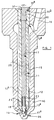
- a fuel injector includes a nozzle body 10 having a blind bore 11 formed therein.
- the blind end of the bore 11 is shaped to be of frusto-conical form and defines first and second seating surfaces 13 a , 13 b .
- An outer valve needle 12 is slidable within the bore 11 and is engageable with the first seating 13 a to control fuel delivery through a first set of outlet openings 14 (only one of which is shown).
- the valve needle 12 and bore 11 together define a delivery chamber 15 which communicates with a source of fuel at high pressure by means of a supply passage 16 defined, in part, within an upper part of the nozzle body 10.
- the outer valve needle 12 cooperates with the first seating 13 a to control communication between the delivery chamber 15 and the first outlet opening 14.
- the outer valve needle 12 is reciprocable within the bore 11 under the control of an appropriate control arrangement which controls the distance through which the outer valve needle 12 can move away from the first seating 13 a .
- the control arrangement may comprise, for example, a piezoelectric actuator arrangement which includes a piezoelectric actuator element or stack.
- the outer valve needle 12 is provided with one or more thrust surfaces 12 a , fuel pressure within the delivery chamber 15 acting on the thrust surfaces 12 a to urge the valve needle away from the first seating 13 a , in use.
- the outer valve needle 12 also includes an enlarged region 12 c extending radially from one section of the outer valve needle 12, the enlarged region 12c having substantially the same diameter as the adjacent part of the bore 11.
- the outer valve needle 12 may be provided with flats or slots (not shown) on the outer surface to permit fuel in the delivery chamber 15 to flow past the enlarged region 12c.
- the outer valve needle 12 further includes an end region 12 b , the end region 12 b being shaped so as to be capable of deformation when the axial load applied to the outer valve needle 12 is increased beyond a predetermined amount.
- the outer valve needle 12 is provided with a through bore 17 including a region 17 a of reduced diameter within which an inner valve needle 18 is slidable, the inner valve needle 18 having a tip region 18 a which extends into a sac region 19 defined by the blind end of the bore 11.
- the bore 17 is shaped to define a further seating surface 20 of substantially frusto-conical form with which a region 22 of the inner valve needle 18 is engageable.
- the seating 20 defined by the bore 17 and the region 22 together define a clearance gap such that, in use, when the outer valve needle 12 is moved inwardly within the bore 11 away from the first seating 13 a by an amount greater than the clearance gap, the seating 20 engages the region 22 causing movement of the outer valve needle 12 to be transmitted to the inner valve needle 18.
- the bore 17 defines a spring chamber 23 within which a compression spring 24 is housed, the compression spring 24 serving to urge the inner valve needle 18 downwardly against the second seating 13 b such that the tip region 18 a of the inner valve needle 18 covers a second set of outlet openings 26 (only one of which is shown) provided in the nozzle body 10.
- the tip region 18 a of the valve needle 18 uncovers the second set of outlet openings 26 to permit fuel delivery therethrough.
- the inner valve needle 18 and the outer valve needle 12 together define a clearance 27 which permits fuel to enter and escape from the spring chamber 23, in use.
- One end of the compression spring 24 abuts the upper end surface of the inner valve needle 18, the other end of the compression spring 24 being in abutment with the lower end surface of a spacer member 28 which is received within bore 17.
- the spacer member 28 abuts a valve insert member 30 provided with a surface 30 b , the valve insert member 30 being received within the bore 17 and the surface 30b being engageable with a corresponding additional seating 32 defined by the bore 17.
- the spacer member 28 and the valve insert member 30 may be integrally or separately formed.
- the valve insert member 30 includes, at its uppermost end, a region 30 a of enlarged diameter, the upper end surface of the valve insert member 30 therefore being of increased diameter.
- the enlarged upper end surface of the valve insert member 30 may be acted on by means of a spring (not shown) which serves to urge the valve insert member 30, and hence the outer valve needle 12, inwardly within the bore 11.
- the enlarged upper end surface may also define, in part, a control chamber 31 for fuel, fuel pressure within the control chamber 31 being varied so as to control movement of the outer valve needle 12 within the bore 11.
- the spacer member 28 and the valve insert member 30 are slidable within the bore 17 such that, in use, if fuel pressure within the chamber 23 defined, in part, by the bore 17, exceeds that in the control chamber 31, the spacer member 28 is moved upwardly within the bore 17 causing the surface 30 b to lift away from the seating 32. Fuel is therefore able to escape from the chamber 23 to the control chamber 31 to reduce fuel pressure within the chamber 23.
- the seating 32 defined by the bore 17 with which the valve insert member 30 is engageable to control fuel flow between the spring chamber 23 and the control chamber is provided part way along the length of the bore 17. By providing the seating 32 at or very close to the open end of the bore 17, manufacturability of the injector is improved.
- the inner valve needle 18 includes a further region 34 of substantially frusto-conical form, the further region 34 being located downstream of the region 22.
- the further region 34 adopts a position downstream of the seating 20.
- the region 22 of the inner valve needle 18 is also provided with one or more flats or grooves 36 such that, when the region 22 of the inner valve needle 18 is seated against the seating 20, the fuel is able to flow to and from the chamber 23 past the region 22.
- the fuel injector is arranged such that the delivery chamber 15 is supplied with fuel through the supply passage 16 from a source of fuel under high pressure, for example, the common rail of a common rail fuel system, the common rail being charged to a high pressure by an appropriate high pressure fuel pump.
- a source of fuel under high pressure for example, the common rail of a common rail fuel system, the common rail being charged to a high pressure by an appropriate high pressure fuel pump.
- the actuator arrangement Prior to commencement of injection, the actuator arrangement is operated in such a manner that the outer valve needle 12 engages the first seating 13 a .
- the compression spring 24 biases the inner valve needle 18 against the second seating 13 b , the tip region 18 a of the inner valve needle 18 covering the second set of outlet openings 26.
- fuel injection does not therefore take place.
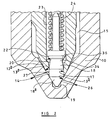
- the actuator arrangement When fuel injection is to be commenced, the actuator arrangement is operated in such a manner that the valve insert member 30, the spacer member 28 and the outer valve needle 12 are moved in an upwards direction, causing the outer valve needle 12 to be lifted away from the first seating 13 a to the position shown in Figure 3 . Lifting may be aided by the action of the fuel under pressure within the delivery chamber 15 acting upon the thrust surface 12 a of the outer valve needle 12. Upward movement of the outer valve needle 12 away from the first seating 13 a permits fuel to flow from the delivery chamber 15 past the first seating 13 a and out through the first set of outlet openings 14.
- the outer valve needle 12 is only moved upwardly through a distance which is less than the clearance gap defined between the region 22 of the valve needle 18 and the seating 20 defined by the bore 17, the seating 20 does not move into engagement with the region 22 of the inner valve needle 18.
- the inner valve needle 18 therefore remains in engagement with the second seating 13b under the action of the spring 24 and fuel pressure within the chamber 23.
- fuel is unable to flow past the second seating 13 b out through the second set of outlet openings 26. It will therefore be appreciated that, as fuel is only injected through the first set of outlet openings 14, injection of fuel occurs at a relatively low rate for a given applied fuel pressure.
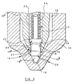
- the actuator arrangement When the fuel is to be injected at a higher rate for a given fuel pressure, the actuator arrangement is actuated such that the valve insert member 30, the spacer member 28 and the outer valve needle 12 are moved through a further distance into the position shown in Figure 4 , further movement of the outer valve needle 12 away from the first seating 13 a resulting in the seating 20 moving into engagement with the region 22 of the inner valve needle 18. Movement of the outer valve needle 12 is therefore transmitted to the inner valve needle 18 and the inner valve needle 18 lifts away from the second seating 13 b . As a result, fuel is able to flow from the delivery chamber 15 past the second seating surface 13 b and out through the second set of outlet openings 26. As fuel is delivered through both the first and second set of outlet openings 14, 26 during this stage of operating, it will be appreciated that fuel is delivered at a relatively high rate for a given fuel pressure.
- the actuator is operated such that the outer valve needle 12 is returned to the position illustrated in Figures 1 and 2 in which the outer valve needle 12 engages the first seating 13 a and the tip region 18 a of the inner valve needle 18 engages the second seating 13 b . It will be appreciated that, prior to engagement of the outer valve needle 12 with the first seating 13 a , the tip region 18 a of the inner valve needle 18 moves into engagement with the second seating 13b. It will therefore be appreciated that termination of fuel injection through the second set of outlet openings 26 occurs prior to termination of injection through the first set of outlet openings 14.
- the end region 12 b of the outer valve needle 12 is deformable, when an increased axial load is applied to the valve insert member 30 to urge the outer valve needle 12 against the first seating 13 b , the end region 12 b of the outer valve needle 12 deforms inwardly and co-operates with the inner valve needle 18 so as to form a substantially fluid tight seal.
- the seal formed between the inner valve needle 18 and the region 12 b of the outer valve needle closes the clearance 27 and, thus, any fuel remaining in the chamber 23 following an injection of fuel cannot escape from the chamber 23 through the clearance passage 27. Undesirable leakage of fuel through the first and second outlet openings 14, 26 during this non-injecting stage is therefore substantially avoided.
- the chamber 23 is sealed when the end region 12 b of the outer valve needle 12 deforms, exhaust gases from the engine cylinder or other combustion space cannot flow into the chamber 23 and contaminate fuel therein.
- the outer valve needle 12 lifts away from the first seating 13 a and the end region 12 b deforms outwardly so as to move away from the inner valve needle 18, breaking the fluid tight seal and opening the clearance 27.
- fuel is able to escape from the chamber 23 through the clearance 27 defined between the outer valve needle 12 and the inner valve needle 18.
- Fuel is also able to enter the chamber 23 to re-pressurise the chamber 23 if the pressure in the delivery chamber 15 exceeds that in the chamber 23. As fuel is able to enter and escape from the chamber 23 through the clearance passage 27, fuel is prevented from becoming trapped within the chamber 23. The effects of fuel degradation are therefore minimised.
- the valve insert member 30 also provides a means of venting the chamber 23 during the fuel injecting cycle.
- the amount of fuel which flows from the spring chamber 23 to the control chamber at the uppermost end of the outer valve needle 12 is determined by the fuel pressure difference between these two chambers, the length of time that the pressure difference is maintained and the fuel flow area through which the fuel flows.
- the fuel flow area may be increased by including further flats or slots on the surface of the valve insert member 30.
- the fuel pressure difference and the length of time that the fuel pressure difference is maintained are determined by the operating conditions and the type of actuator arrangement use to control movement outer valve needle 12.
- the fuel injection of the present invention is also advantageous in that, just prior to the point when the outer valve needle 12 moves into engagement with the region 22 of the inner valve needle 18, the stresses in the inner valve needle 18 are reduced due to the frusto-conical shaping of the further region 34. Additionally, the seating 20 defined by the bore 17 and the region 22, both being of substantially frusto-conical form, are relatively easy to manufacture.
- first and second sets of outlet openings 14, 26 having a different number of openings, or having openings of different size, or having openings providing a different spray pattern
- the fuel injection characteristic for example the fuel injection rate, may be varied in use by injecting fuel through one or both sets of outlet openings.
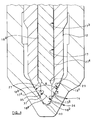
- FIG. 5 to 7 there is shown an alternative embodiment of the present invention in which similar parts to those shown in Figures 1 to 4 are denoted with like reference numerals.
- the embodiment shown in Figures 5 to 7 differs from that shown in Figures 1 to 4 in that the inner valve needle 18 is of elongate form and the seating 20 is positioned relatively close to the uppermost open end of the bore 17, and remote from the deformable region 12 b of the outer valve needle. Manufacturability of the injector is therefore improved as it is more difficult to form the seating 20 close to the lowermost, open end of the bore 17, as shown in Figure 1 . It will be appreciated that, as the inner valve needle 18 is of elongate form, the need for the spacer member 28 is removed.
- the through bore 17 provided in the outer valve needle 12 includes a region 17 a of reduced diameter, an intermediate region 17 b of intermediate diameter and an upper region 17c of enlarged diameter.
- the inner valve needle 18 includes a lower, tip region 18 a of reduced diameter, an upper region 18c of enlarged diameter and an intermediate region 18d of intermediate diameter.
- the region 18 a of the inner valve needle 18 terminates in a tip portion 18 b which extends into the sac region 19.
- the diameters of the lower region 18 a of the inner valve needle 18 and of the region 17 a of the bore 17, and the diameters of the enlarged region 17c of the bore and the enlarged region 18c of the inner valve needle 18, are such that movement of the valve needle 12 within the bore 17 is guided.
- the interconnection between the regions 17 b , 17 c of the bore 17 forms a step which defines the seating 20 with which a surface of the region 18 c of the inner valve needle 18 is engageable.
- the spring chamber 23 communicates, by means of a clearance 27 a defined between the region 17 b of the bore 17 and the region 18 d of the inner valve needle 18, with a further chamber 29 defined, in part, within the bore 17.
- the lower region 18 a of the inner valve needle 18 and the region 12 b of the outer valve needle 12 together define a clearance 27 which permits fuel to enter and escape from the chamber 29, in use.
- fuel is able to enter and escape from the chamber 23, in use, through the clearances 27, 27 a .
- One end of the compression spring 24 abuts a part of the upper end surface of the region 18c of the inner valve needle 18, the other end of the compression spring 24 being in abutment with the lower end surface of the valve insert member 30 which is slidable within a region 17 d of the bore 17.
- the valve insert member 30 is slidable within the region 17d of the bore 17 such that, in use, if fuel pressure within the chamber 23 exceeds fuel pressure within the control chamber 31, the valve insert member 30 is moved upwardly within the bore region 17d causing the surface 30 b thereof to lift away from the seating 32. Fuel is therefore able to vent from the chamber 23 to the control chamber 31 to reduce fuel pressure within the chamber 23.
- the outer surface of the region 12 b of the outer valve needle 12 is shaped such that, when the outer valve needle 12 adopts a first position in which the surface of the region 12 b engages the first seating 13 a , a clearance 35 is defined by a portion of the region 12 b downstream of the seating 13 a and the adjacent part of the bore 11.
- the clearance 35 communicates with a limited volume 37 defined by the bore 11, the region 18 a and the region 12 b .
- the region 12 b of the outer valve needle 12 may be shaped such that the angle ⁇ (as shown in Figure 6 ) subtended by the region 12 b in the region of engagement with the seating 13 a is approximately 60° and the angle ⁇ subtended by the clearance 35 is approximately 0.125°.
- the outer valve needle 12 will be caused to move to a second position (as shown in Figure 7 ), a portion of the region 12 b downstream of the first seating 13 a deforming to close the clearance 35, and hence closing the first set of outlet openings 14, as will be described in further detail hereinafter.
- the actuator arrangement In use, with fuel under high pressure delivered through the supply passage 16 and prior to commencement of injection, the actuator arrangement is operated in such a manner that the region 12 b of the outer valve needle 12 engages the first seating 13 a . As a result, fuel within the delivery chamber 15 is unable to flow past the seating 13 a out through the first set of outlet openings 14. During this stage of the operation, the compression spring 24 biases the inner valve needle 18 against the second seating 13 b , such that the lower region 18 a of the inner valve needle 18 closes the second set of outlet openings 26. As fuel is unable to flow past the first and second seatings 13 a , 13 b , fuel injection does not therefore take place.
- the actuator arrangement When fuel injection is to be commenced, the actuator arrangement is operated in such a manner that the valve insert member 30 and the outer valve needle 12 are moved in an upwards direction, causing the outer valve needle 12 to be lifted away from the first seating 13 a .
- Such lifting movement may be aided by the action of fuel under pressure within the delivery chamber 15 acting on the thrust surfaces 12 a of the outer valve needle 12. Upward movement of the outer valve needle 12 away from the first seating 13 a permits fuel to flow from the delivery chamber 15 past the first seating 13 a and out through the first set of outlet openings 14.
- the outer valve needle 12 is only moved upwardly through a distance which is less than the clearance gap defined between the region 18 c of the inner valve needle 18 and the seating 20 defined by the bore 17, the seating 20 does not move into engagement with the region 18c.
- the inner valve needle 18 therefore remains in engagement with the second seating 13 b under the action of the spring 24 and fuel pressure within the chamber 23.
- fuel within the delivery chamber 15 is unable to flow past the second seating 13 b out through the second set of outlet openings 26.
- injection of fuel occurs only at a relatively low rate for a given applied fuel pressure.
- the actuator arrangement When the fuel is to be injected at a higher rate for a given fuel pressure, the actuator arrangement is actuated such that the valve insert member 30 and the outer valve needle 12 are moved through a further distance, further movement of the outer valve needle 12 away from the first seating 13 a resulting in the seating 20 moving into engagement with the region 18 c of the inner valve needle 18. Movement of the outer valve needle 12 is therefore transmitted to the inner valve needle 18 such that the inner valve needle 18 lifts away from the second seating 13 b . As a result, fuel is able to flow from the delivery chamber 15 past the second seating surface 13 b and out through the second set of outlet openings 26. Thus, as fuel is delivered through both the first and second sets of outlet openings 14, 26, fuel is delivered at a relatively high rate for a given fuel pressure.
- the actuator is operated such that the outer valve needle 12 is returned, initially, to the position illustrated in Figure 6 in which the region 12 b of the outer valve needle 12 engages the first seating 13 a and the lower region 18 a of the inner valve needle 18 engages the second seating 13 b .
- the region 12 b of the outer valve needle 12 With the region 12 b of the outer valve needle 12 seated against the seating 13 a , the pressure of fuel downstream of the seating 13 a will reduce to a value significantly less than fuel pressure within the control chamber 31.
- the portion of the region 12 b of the outer valve needle 12 downstream of the seating 13 a will therefore deform to close the clearance 35, as shown in Figure 7 , causing the first set of outlet openings 14 to be closed.
- Deformation of the region 12 b to close the first set of outlet openings 14 prevents any residual fuel within the volume 37 from escaping into the engine cylinder or other combustion space. Additionally, as the outer valve needle 12 deforms to close the first set of outlet openings 14, the volume 37 within which fuel can reside is considerably reduced compared with known fuel injectors of this type. This provides the advantage that the volume of fuel exposed to exhaust gases within the engine cylinder is reduced, thereby reducing undesirable emissions. Furthermore, as can be seen in Figure 7 , as the region 18 a of the inner valve needle 18 covers the second set of outlet openings 26 during this stage of operation, any residual fuel within the volume 37 and the sac region 19 will be unable to escape to the engine cylinder through the second set of outlet openings 26.
- the shaping of the region 12 b of the outer valve needle 12 and of the adjacent part of the bore 11 provided in the nozzle body 10 is preferably arranged to ensure that closure of the first set of outlet openings 14 by deformation of the region 12 b occurs at minimum rail pressure.
- This will vary for different fuel injector applications.
- the region 18 a of the inner valve needle 18 may have a diameter of 1 mm
- the angle ⁇ subtended by the region 12 b may be 60°
- the angle ⁇ subtended by the clearance 35 may be approximately 0.125°
- the first seating 13 a may have a diameter of 2.25 mm.
- a fuel injector having these dimensions will cause the region 12 b of the outer valve needle 12 to deform to close the first set of outlet openings 14 at a rail pressure of approximately 500 Bar.
- the region 12 b of the outer valve needle 12 in Figures 5 to 7 may also be arranged such that it deforms inwardly and cooperates with the region 18 a of the inner valve needle 18 to form a substantially fluid tight seal.
- the seal formed between the region 18 a of the inner valve needle 18 and the region 12 b of the outer valve needle 12 closes the clearance 27 and any fuel remaining within the chambers 23, 29 following an injection of fuel cannot therefore escape through the clearance 27. Undesirable leakage of fuel into the volume 37 and out through the first and second outlet openings 14, 26 is therefore further reduced.
- the seal formed between the region 12 b of the outer valve needle and the region 18 a of the inner valve needle and the seal formed at the seating 32 ensures the chambers 23, 29 are sealed when the region 12 b of the outer valve needle 12 deforms.
- exhaust gases from the engine cylinder of other combustion space cannot flow into the chambers 29, 23 and contaminate any fuel therein.
- each of the first and second sets 14, 26 may be provided in each of the first and second sets 14, 26.
- the second set of outlet openings 26 does not communicate with the sac region 19 in the embodiments of the invention described herein, it will be appreciated that the fuel injector may be of the type in which the second set of outlet openings 26 does communicate directly with the sac region 19.
- the spring 24 has been referred to as a compression spring, it will be appreciated that any other resilient bias arrangements could be used. It will also be appreciated that, if desired, the inner valve needle 18 may itself be provided with a bore within which a further valve needle is slidable to control delivery of fuel through one or more further outlet openings or groups of outlet openings.
Landscapes
- Engineering & Computer Science (AREA)
- Chemical & Material Sciences (AREA)
- Combustion & Propulsion (AREA)
- Mechanical Engineering (AREA)
- General Engineering & Computer Science (AREA)
- Physics & Mathematics (AREA)
- Fluid Mechanics (AREA)
- Fuel-Injection Apparatus (AREA)
Claims (9)
- Injecteur de carburant comprenant un corps d'injecteur (10) ayant un premier alésage (11) définissant des premier et second sièges (13a, 13b), un pointeau de soupape externe (12) pouvant coulisser à l'intérieur du premier alésage (11) et comprenant une région d'extrémité (12b), pouvant être mise en prise avec le premier siège (13a) pour réguler l'écoulement de carburant d'une première ouverture de sortie (14), le pointeau de soupape externe (12) étant doté d'un second alésage (17) à l'intérieur duquel peut coulisser un pointeau de soupape interne (18), le pointeau de soupape interne (18) pouvant être mis en prise avec le second siège (13b) pour réguler la distribution de carburant à travers une seconde ouverture de sortie (26), l'injecteur de carburant étant caractérisé en ce que la région d'extrémité (12b) du pointeau de soupape externe (12) est déformable et façonnée de sorte que, pendant l'utilisation, lorsque le pointeau de soupape externe (12) est amené contre le premier siège (13a), la région d'extrémité (12b) du pointeau de soupape externe (12) se déforme pour fermer la première ouverture de sortie (14).
- Injecteur de carburant selon la revendication 1, dans lequel la région déformable (12b) est façonnée de sorte que, pendant l'utilisation, lorsque le pointeau de soupape externe (12) est amené contre le premier siège (13a), le pointeau de soupape externe (12) coopère avec le pointeau de soupape interne (18) pour former un joint sensiblement étanche au fluide.
- Injecteur de carburant selon la revendication 2, dans lequel une chambre (23) est définie à l'intérieur du second alésage (17), moyennant quoi la coopération entre la région déformable (12b) du pointeau de soupape externe (12) et le pointeau de soupape interne (18) lorsque le pointeau de soupape externe (12) est amené contre le premier siège (13a) rend la chambre (23) sensiblement hermétique.
- Injecteur de carburant selon l'une quelconque des revendications 1 à 3, dans lequel le pointeau de soupape interne (18) et le pointeau de soupape externe (12) sont agencés de telle sorte que le mouvement du pointeau de soupape externe (12) à l'écart du premier siège (13a) au-delà d'une quantité prédéterminée est transmis au pointeau de soupape interne (18), déplaçant ainsi le pointeau de soupape interne (18) loin du second siège (13b).
- Injecteur de carburant selon la revendication 4, dans lequel le pointeau de soupape externe (12) est doté d'une surface (20) qui peut être mise en prise avec une première région (22) du pointeau de soupape interne (18) pour transmettre le mouvement du pointeau de soupape externe (12) au pointeau de soupape interne (18), dans lequel la première région (22) et la surface (20) sont de forme sensiblement tronconique.
- Injecteur de carburant selon la revendication 5, dans lequel la surface (20) du pointeau de soupape externe (12) qui peut être mise en prise avec la première région (22) du pointeau de soupape interne (18) est située sur le pointeau de soupape externe (12) à une position distante de la région déformable (12b).
- Injecteur de carburant selon la revendication 5 ou la revendication 6, dans lequel le pointeau de soupape interne (18) comprend une seconde région (34) située en aval de la première région (22), la seconde région (34) étant de forme sensiblement tronconique de telle sorte que les contraintes dans la seconde région (34) du pointeau de soupape interne (18) soient minimisées lors de la mise en prise entre la surface (20) du pointeau de soupape externe (12) et la première région (22) du pointeau de soupape interne (18).
- Injecteur de carburant selon l'une quelconque des revendications 1 à 7, comprenant en outre un élément d'insert de soupape (30) reçu dans une région supérieure (17d) du second alésage (17), l'élément d'insert de soupape (30) pouvant être mis en prise avec un siège supplémentaire (32) défini par l'extrémité ouverte du second alésage (17) distant du pointeau de soupape interne (18) pour permettre au carburant en amont du pointeau de soupape interne (18) de s'évacuer par le second alésage (17).
- Injecteur de carburant selon la revendication 8, comprenant en outre un élément d'entretoise (28) reçu à l'intérieur du second alésage (17) prévu dans le pointeau de soupape externe (12), l'élément d'entretoise étant intercalé entre le pointeau de soupape interne et l'élément d'insert de soupape.
Priority Applications (1)
| Application Number | Priority Date | Filing Date | Title |
|---|---|---|---|
| EP20080101317 EP2003323B1 (fr) | 1999-10-06 | 2000-10-05 | Injecteur de carburant |
Applications Claiming Priority (4)
| Application Number | Priority Date | Filing Date | Title |
|---|---|---|---|
| GB9923479 | 1999-10-06 | ||
| GBGB9923479.1A GB9923479D0 (en) | 1999-10-06 | 1999-10-06 | Fuel injector |
| GBGB9926787.4A GB9926787D0 (en) | 1999-11-13 | 1999-11-13 | Fuel injector |
| GB9926787 | 1999-11-13 |
Related Child Applications (1)
| Application Number | Title | Priority Date | Filing Date |
|---|---|---|---|
| EP20080101317 Division EP2003323B1 (fr) | 1999-10-06 | 2000-10-05 | Injecteur de carburant |
Publications (3)
| Publication Number | Publication Date |
|---|---|
| EP1091117A2 EP1091117A2 (fr) | 2001-04-11 |
| EP1091117A3 EP1091117A3 (fr) | 2003-07-30 |
| EP1091117B1 true EP1091117B1 (fr) | 2008-04-02 |
Family
ID=26315978
Family Applications (2)
| Application Number | Title | Priority Date | Filing Date |
|---|---|---|---|
| EP20080101317 Expired - Lifetime EP2003323B1 (fr) | 1999-10-06 | 2000-10-05 | Injecteur de carburant |
| EP20000308802 Expired - Lifetime EP1091117B1 (fr) | 1999-10-06 | 2000-10-05 | Injecteur de carburant |
Family Applications Before (1)
| Application Number | Title | Priority Date | Filing Date |
|---|---|---|---|
| EP20080101317 Expired - Lifetime EP2003323B1 (fr) | 1999-10-06 | 2000-10-05 | Injecteur de carburant |
Country Status (4)
| Country | Link |
|---|---|
| US (1) | US6338445B1 (fr) |
| EP (2) | EP2003323B1 (fr) |
| AT (2) | ATE391232T1 (fr) |
| DE (2) | DE60044626D1 (fr) |
Families Citing this family (72)
| Publication number | Priority date | Publication date | Assignee | Title |
|---|---|---|---|---|
| DE19916485C2 (de) * | 1999-04-13 | 2001-10-31 | Daimler Chrysler Ag | Verfahren zum Betrieb einer Hubkolbenbrennkraftmaschine |
| GB9914644D0 (en) * | 1999-06-24 | 1999-08-25 | Lucas Ind Plc | Fuel injector |
| US6338445B1 (en) * | 1999-10-06 | 2002-01-15 | Delphi Technologies, Inc. | Fuel injector |
| GB9923823D0 (en) | 1999-10-09 | 1999-12-08 | Lucas Industries Ltd | Fuel injector |
| ES2280318T3 (es) | 2000-07-18 | 2007-09-16 | Delphi Technologies, Inc. | Inyector de combustible. |
| GB0107575D0 (en) * | 2001-03-27 | 2001-05-16 | Delphi Tech Inc | Control valve arrangement |
| JP3518521B2 (ja) * | 2001-04-11 | 2004-04-12 | トヨタ自動車株式会社 | 内燃機関の燃料噴射制御装置 |
| DE10118699A1 (de) * | 2001-04-17 | 2002-10-31 | Bosch Gmbh Robert | Kraftstoff-Einspritzvorrichtung und Kraftstoffsystem für Brennkraftmaschinen, sowie Brennkraftmaschine |
| US6601566B2 (en) | 2001-07-11 | 2003-08-05 | Caterpillar Inc | Fuel injector with directly controlled dual concentric check and engine using same |
| DE10141678A1 (de) * | 2001-08-25 | 2003-05-08 | Bosch Gmbh Robert | Kraftstoffeinspritzeinrichtung für eine Brennkraftmaschine |
| US6725838B2 (en) | 2001-10-09 | 2004-04-27 | Caterpillar Inc | Fuel injector having dual mode capabilities and engine using same |
| US7252249B2 (en) | 2002-02-22 | 2007-08-07 | Delphi Technologies, Inc. | Solenoid-type fuel injector assembly having stabilized ferritic stainless steel components |
| US6769635B2 (en) | 2002-09-25 | 2004-08-03 | Caterpillar Inc | Mixed mode fuel injector with individually moveable needle valve members |
| EP1563181B1 (fr) * | 2002-11-11 | 2006-10-04 | Robert Bosch Gmbh | Soupape d'injection de carburant pour moteurs combustion interne |
| US6945475B2 (en) | 2002-12-05 | 2005-09-20 | Caterpillar Inc | Dual mode fuel injection system and fuel injector for same |
| DE10312586A1 (de) * | 2003-03-21 | 2004-09-30 | Robert Bosch Gmbh | Kraftstoffeinspritzventil für Brennkraftmaschinen |
| DE10313225A1 (de) * | 2003-03-25 | 2004-10-07 | Robert Bosch Gmbh | Kraftstoffeinspritzventil für Brennkraftmaschine |
| DE10322826A1 (de) * | 2003-05-19 | 2004-12-09 | Robert Bosch Gmbh | Kraftstoffeinspritzventil für Brennkraftmaschinen |
| DE10326044A1 (de) * | 2003-06-10 | 2004-12-30 | Robert Bosch Gmbh | Einspritzdüse für Brennkraftmaschinen |
| DE10343998A1 (de) * | 2003-09-23 | 2005-04-14 | Robert Bosch Gmbh | Einspritzdüse |
| DE10348978A1 (de) * | 2003-10-22 | 2005-05-25 | Robert Bosch Gmbh | Kraftstoff-Einspritzvorrichtung, insbesondere für eine Brennkraftmaschine mit Direkteinspritzung |
| US7225996B2 (en) * | 2003-12-25 | 2007-06-05 | Kawasaki Jukogyo Kabushiki Kaisha | Fuel supply method and fuel supply system for fuel injection device |
| EP1559903B1 (fr) * | 2004-01-28 | 2008-12-10 | Continental Automotive Italy S.p.A. | Injecteur de carburant avec aiguille déformable |
| EP2618215B1 (fr) * | 2004-05-31 | 2017-07-05 | Fujifilm Corporation | Procédé de fabrication d'une plaque d'impression lithographique |
| EP1637730B1 (fr) * | 2004-09-17 | 2014-04-16 | Delphi International Operations Luxembourg S.à r.l. | Injecteur de combustible et procédé de fabrication |
| DE602005001261T2 (de) * | 2005-01-19 | 2008-01-31 | Delphi Technologies, Inc., Troy | Brennstoffeinspritzventil |
| FR2881185A1 (fr) * | 2005-01-26 | 2006-07-28 | Magneti Marelli Motopropulsion | Injecteur de carburant et moteur comprenant un tel injecteur |
| JP4315115B2 (ja) * | 2005-03-10 | 2009-08-19 | 株式会社デンソー | 燃料噴射弁 |
| US7347182B2 (en) * | 2005-04-06 | 2008-03-25 | Gm Global Technology Operations, Inc. | Injector double row cluster configuration for reduced soot emissions |
| DE602005005982T2 (de) * | 2005-07-13 | 2009-05-14 | Delphi Technologies, Inc., Troy | Einspritzdüse |
| US7793588B2 (en) * | 2005-08-22 | 2010-09-14 | Goss International Americas, Inc. | Spray pattern valve body |
| JP4294671B2 (ja) * | 2006-01-26 | 2009-07-15 | 株式会社デンソー | 燃料噴射装置 |
| CN100354519C (zh) * | 2006-01-27 | 2007-12-12 | 大连理工大学 | 双柱塞式供油泵 |
| US20080166563A1 (en) * | 2007-01-04 | 2008-07-10 | Goodrich Corporation | Electrothermal heater made from thermally conducting electrically insulating polymer material |
| US8074625B2 (en) | 2008-01-07 | 2011-12-13 | Mcalister Technologies, Llc | Fuel injector actuator assemblies and associated methods of use and manufacture |
| US8387599B2 (en) * | 2008-01-07 | 2013-03-05 | Mcalister Technologies, Llc | Methods and systems for reducing the formation of oxides of nitrogen during combustion in engines |
| US8561598B2 (en) * | 2008-01-07 | 2013-10-22 | Mcalister Technologies, Llc | Method and system of thermochemical regeneration to provide oxygenated fuel, for example, with fuel-cooled fuel injectors |
| US8413634B2 (en) | 2008-01-07 | 2013-04-09 | Mcalister Technologies, Llc | Integrated fuel injector igniters with conductive cable assemblies |
| US8365700B2 (en) * | 2008-01-07 | 2013-02-05 | Mcalister Technologies, Llc | Shaping a fuel charge in a combustion chamber with multiple drivers and/or ionization control |
| US8635985B2 (en) | 2008-01-07 | 2014-01-28 | Mcalister Technologies, Llc | Integrated fuel injectors and igniters and associated methods of use and manufacture |
| US7628137B1 (en) | 2008-01-07 | 2009-12-08 | Mcalister Roy E | Multifuel storage, metering and ignition system |
| JP2009162184A (ja) * | 2008-01-09 | 2009-07-23 | Toyota Motor Corp | 燃料噴射弁 |
| DE102009027727A1 (de) * | 2009-07-15 | 2011-01-20 | Robert Bosch Gmbh | Ventilanordnung |
| CN102713244A (zh) | 2009-08-27 | 2012-10-03 | 麦卡利斯特技术有限责任公司 | 在具有多个驱动器和/或电离控制的燃烧室中成形供应燃料 |
| MX2012006565A (es) * | 2009-12-07 | 2012-08-23 | Mcalister Technologies Llc | Sistema de control adaptable para inyectores de combustible. y dispositivos de encendido. |
| EP2534364A4 (fr) | 2010-02-13 | 2014-04-23 | Mcalister Technologies Llc | Ensembles injecteurs de combustible comprenant des modificateurs de force acoustique, et procédés d'utilisation et de fabrication associés |
| US20110297753A1 (en) | 2010-12-06 | 2011-12-08 | Mcalister Roy E | Integrated fuel injector igniters configured to inject multiple fuels and/or coolants and associated methods of use and manufacture |
| EP2534347B1 (fr) | 2010-02-13 | 2016-05-04 | McAlister, Roy Edward | Procédés et systèmes de refroidissement adaptatif de chambres de combustion dans des moteurs |
| US8602319B2 (en) * | 2010-10-07 | 2013-12-10 | Caterpillar Inc. | Needle valve member with frustoconical guide segment and fuel injector using same |
| US8528519B2 (en) | 2010-10-27 | 2013-09-10 | Mcalister Technologies, Llc | Integrated fuel injector igniters suitable for large engine applications and associated methods of use and manufacture |
| US8091528B2 (en) | 2010-12-06 | 2012-01-10 | Mcalister Technologies, Llc | Integrated fuel injector igniters having force generating assemblies for injecting and igniting fuel and associated methods of use and manufacture |
| DE102011003939A1 (de) * | 2011-02-10 | 2012-08-16 | Continental Automotive Gmbh | Registerdüse |
| WO2012112615A1 (fr) | 2011-02-14 | 2012-08-23 | Mcalister Technologies, Llc | Moteurs multiplicateurs de couple |
| CN103890343B (zh) | 2011-08-12 | 2015-07-15 | 麦卡利斯特技术有限责任公司 | 用于改进的发动机冷却及能量产生的系统和方法 |
| WO2013025626A1 (fr) | 2011-08-12 | 2013-02-21 | Mcalister Technologies, Llc | Ensemble vanne de réglage de débit à actionnement acoustique comprenant une pluralité de soupapes flexibles |
| US9651013B2 (en) * | 2012-04-24 | 2017-05-16 | International Engine Intellectual Property Company, Llc | Low leakage seat valve guide |
| EP2672101A1 (fr) * | 2012-06-05 | 2013-12-11 | Caterpillar Motoren GmbH & Co. KG | Buse d'injection |
| JP5983133B2 (ja) * | 2012-07-20 | 2016-08-31 | 株式会社デンソー | 燃料噴射弁 |
| US8851047B2 (en) | 2012-08-13 | 2014-10-07 | Mcallister Technologies, Llc | Injector-igniters with variable gap electrode |
| US9200561B2 (en) | 2012-11-12 | 2015-12-01 | Mcalister Technologies, Llc | Chemical fuel conditioning and activation |
| US8800527B2 (en) | 2012-11-19 | 2014-08-12 | Mcalister Technologies, Llc | Method and apparatus for providing adaptive swirl injection and ignition |
| US8820293B1 (en) | 2013-03-15 | 2014-09-02 | Mcalister Technologies, Llc | Injector-igniter with thermochemical regeneration |
| US9562500B2 (en) | 2013-03-15 | 2017-02-07 | Mcalister Technologies, Llc | Injector-igniter with fuel characterization |
| CN105636705B (zh) * | 2013-09-16 | 2018-06-19 | 泰华施公司 | 用于分配系统的喷嘴 |
| JP6079570B2 (ja) * | 2013-11-06 | 2017-02-15 | トヨタ自動車株式会社 | 内燃機関 |
| EP2896811B1 (fr) * | 2014-01-15 | 2016-10-19 | Continental Automotive GmbH | Ensemble de buse et soupape d'injection de carburant pour moteur à combustion interne |
| CN103967671A (zh) * | 2014-05-22 | 2014-08-06 | 中国北方发动机研究所(天津) | 一种双阀可变喷孔面积燃油喷嘴 |
| CN104533684B (zh) * | 2014-11-26 | 2017-07-28 | 中国北方发动机研究所(天津) | 一种双控制阀多密封带燃油喷嘴 |
| RU2700119C2 (ru) * | 2017-10-10 | 2019-09-12 | Федеральное государственное бюджетное образовательное учреждение высшего образования "Московский автомобильно-дорожный государственный технический университет (МАДИ)" | Распылитель для дизельного двигателя |
| JP7206601B2 (ja) * | 2018-03-08 | 2023-01-18 | 株式会社デンソー | 燃料噴射弁および燃料噴射システム |
| CN111075626B (zh) * | 2019-12-19 | 2020-12-18 | 武汉科技大学 | 一种可变喷孔的喷油器 |
| CN110978413B (zh) * | 2019-12-28 | 2021-08-31 | 况仁鹏 | 一种热流道用阀针嘴芯结构及含有该结构的热流道系统 |
Family Cites Families (11)
| Publication number | Priority date | Publication date | Assignee | Title |
|---|---|---|---|---|
| DE2710138A1 (de) * | 1977-03-09 | 1978-09-14 | Maschf Augsburg Nuernberg Ag | Mehrloch-einspritzduese |
| DE2753953A1 (de) * | 1977-12-03 | 1979-06-07 | Daimler Benz Ag | Verfahren zum betrieb einer luftverdichtenden selbstzuendenden brennkraftmaschine sowie geeignetes einspritzventil |
| DE3036583A1 (de) * | 1980-09-27 | 1982-05-13 | Robert Bosch Gmbh, 7000 Stuttgart | Kraftstoffeinspritzduese |
| DE3048304A1 (de) * | 1980-12-20 | 1982-07-29 | Robert Bosch Gmbh, 7000 Stuttgart | "kraftstoffeinspritzduese fuer brennkraftmaschinen" |
| US4759334A (en) * | 1987-08-19 | 1988-07-26 | Edwin Williamson | Method and device for feeding fuel in a fuel system |
| DE4115457A1 (de) * | 1990-05-17 | 1991-11-21 | Avl Verbrennungskraft Messtech | Einspritzduese fuer eine brennkraftmaschine |
| US5823446A (en) * | 1997-02-18 | 1998-10-20 | Awalbro Corporation | Fuel injector valve for liquified fuel |
| US5899389A (en) * | 1997-06-02 | 1999-05-04 | Cummins Engine Company, Inc. | Two stage fuel injector nozzle assembly |
| DE69922087T2 (de) * | 1998-06-24 | 2005-12-01 | Delphi Technologies, Inc., Troy | Brennstoffeinspritzdüse |
| GB9914642D0 (en) | 1999-06-24 | 1999-08-25 | Lucas Ind Plc | Fuel injector |
| US6338445B1 (en) * | 1999-10-06 | 2002-01-15 | Delphi Technologies, Inc. | Fuel injector |
-
2000
- 2000-10-05 US US09/679,790 patent/US6338445B1/en not_active Expired - Fee Related
- 2000-10-05 AT AT00308802T patent/ATE391232T1/de not_active IP Right Cessation
- 2000-10-05 DE DE60044626T patent/DE60044626D1/de not_active Expired - Lifetime
- 2000-10-05 AT AT08101317T patent/ATE472677T1/de not_active IP Right Cessation
- 2000-10-05 EP EP20080101317 patent/EP2003323B1/fr not_active Expired - Lifetime
- 2000-10-05 DE DE2000638479 patent/DE60038479T2/de not_active Expired - Lifetime
- 2000-10-05 EP EP20000308802 patent/EP1091117B1/fr not_active Expired - Lifetime
Also Published As
| Publication number | Publication date |
|---|---|
| DE60038479T2 (de) | 2009-04-09 |
| EP2003323A1 (fr) | 2008-12-17 |
| DE60044626D1 (de) | 2010-08-12 |
| ATE472677T1 (de) | 2010-07-15 |
| EP1091117A3 (fr) | 2003-07-30 |
| US6338445B1 (en) | 2002-01-15 |
| DE60038479D1 (de) | 2008-05-15 |
| ATE391232T1 (de) | 2008-04-15 |
| EP1091117A2 (fr) | 2001-04-11 |
| EP2003323B1 (fr) | 2010-06-30 |
Similar Documents
| Publication | Publication Date | Title |
|---|---|---|
| EP1091117B1 (fr) | Injecteur de carburant | |
| US6260775B1 (en) | Fuel injector including outer valve needle and inner valve needle slidable within a passage provided in the outer valve needle | |
| EP1382836B1 (fr) | Injecteur à combustible | |
| US6422199B1 (en) | Fuel injector | |
| US6499467B1 (en) | Closed nozzle fuel injector with improved controllabilty | |
| US6467702B1 (en) | Fuel injector | |
| US6513733B1 (en) | Fuel injection and method of assembling a fuel injector | |
| US6616070B1 (en) | Fuel injector | |
| EP1087129A2 (fr) | Injecteur de carburant | |
| US6189817B1 (en) | Fuel injector | |
| US20090266921A1 (en) | Fuel injector with directly triggered injection valve member | |
| US20020148905A1 (en) | Fuel injector arrangement | |
| EP1163440A1 (fr) | Injecteur de carburant | |
| US7744017B2 (en) | Injection nozzle | |
| US20060202052A1 (en) | Fuel injection valve comprising two coaxial valve needles | |
| EP1744050B1 (fr) | Buse d'injection | |
| US6340017B1 (en) | Fuel injector | |
| EP0779430B1 (fr) | Injecteur | |
| EP1707801B1 (fr) | Arrangement de soupapes | |
| EP1033488B1 (fr) | Injecteur de carburant | |
| US20050224593A1 (en) | Fuel injector with hydraulic flow control | |
| KR102244948B1 (ko) | 연료 분사 노즐 | |
| EP1063422B1 (fr) | Injecteur de combustible | |
| WO2009092690A1 (fr) | Injecteur de carburant |
Legal Events
| Date | Code | Title | Description |
|---|---|---|---|
| PUAI | Public reference made under article 153(3) epc to a published international application that has entered the european phase |
Free format text: ORIGINAL CODE: 0009012 |
|
| AK | Designated contracting states |
Kind code of ref document: A2 Designated state(s): AT BE CH CY DE DK ES FI FR GB GR IE IT LI LU MC NL PT SE |
|
| AX | Request for extension of the european patent |
Free format text: AL;LT;LV;MK;RO;SI |
|
| PUAL | Search report despatched |
Free format text: ORIGINAL CODE: 0009013 |
|
| AK | Designated contracting states |
Designated state(s): AT BE CH CY DE DK ES FI FR GB GR IE IT LI LU MC NL PT SE |
|
| AX | Request for extension of the european patent |
Extension state: AL LT LV MK RO SI |
|
| 17P | Request for examination filed |
Effective date: 20040119 |
|
| AKX | Designation fees paid |
Designated state(s): AT BE CH CY DE DK ES FI FR GB GR IE IT LI LU MC NL PT SE |
|
| GRAP | Despatch of communication of intention to grant a patent |
Free format text: ORIGINAL CODE: EPIDOSNIGR1 |
|
| GRAS | Grant fee paid |
Free format text: ORIGINAL CODE: EPIDOSNIGR3 |
|
| GRAA | (expected) grant |
Free format text: ORIGINAL CODE: 0009210 |
|
| AK | Designated contracting states |
Kind code of ref document: B1 Designated state(s): AT BE CH CY DE DK ES FI FR GB GR IE IT LI LU MC NL PT SE |
|
| REG | Reference to a national code |
Ref country code: GB Ref legal event code: FG4D |
|
| REG | Reference to a national code |
Ref country code: CH Ref legal event code: EP Ref country code: IE Ref legal event code: FG4D |
|
| REF | Corresponds to: |
Ref document number: 60038479 Country of ref document: DE Date of ref document: 20080515 Kind code of ref document: P |
|
| NLV1 | Nl: lapsed or annulled due to failure to fulfill the requirements of art. 29p and 29m of the patents act | ||
| PG25 | Lapsed in a contracting state [announced via postgrant information from national office to epo] |
Ref country code: FI Free format text: LAPSE BECAUSE OF FAILURE TO SUBMIT A TRANSLATION OF THE DESCRIPTION OR TO PAY THE FEE WITHIN THE PRESCRIBED TIME-LIMIT Effective date: 20080402 Ref country code: NL Free format text: LAPSE BECAUSE OF FAILURE TO SUBMIT A TRANSLATION OF THE DESCRIPTION OR TO PAY THE FEE WITHIN THE PRESCRIBED TIME-LIMIT Effective date: 20080402 Ref country code: PT Free format text: LAPSE BECAUSE OF FAILURE TO SUBMIT A TRANSLATION OF THE DESCRIPTION OR TO PAY THE FEE WITHIN THE PRESCRIBED TIME-LIMIT Effective date: 20080902 Ref country code: ES Free format text: LAPSE BECAUSE OF FAILURE TO SUBMIT A TRANSLATION OF THE DESCRIPTION OR TO PAY THE FEE WITHIN THE PRESCRIBED TIME-LIMIT Effective date: 20080713 |
|
| PG25 | Lapsed in a contracting state [announced via postgrant information from national office to epo] |
Ref country code: AT Free format text: LAPSE BECAUSE OF FAILURE TO SUBMIT A TRANSLATION OF THE DESCRIPTION OR TO PAY THE FEE WITHIN THE PRESCRIBED TIME-LIMIT Effective date: 20080402 |
|
| ET | Fr: translation filed | ||
| PG25 | Lapsed in a contracting state [announced via postgrant information from national office to epo] |
Ref country code: SE Free format text: LAPSE BECAUSE OF FAILURE TO SUBMIT A TRANSLATION OF THE DESCRIPTION OR TO PAY THE FEE WITHIN THE PRESCRIBED TIME-LIMIT Effective date: 20080702 Ref country code: DK Free format text: LAPSE BECAUSE OF FAILURE TO SUBMIT A TRANSLATION OF THE DESCRIPTION OR TO PAY THE FEE WITHIN THE PRESCRIBED TIME-LIMIT Effective date: 20080402 |
|
| PLBE | No opposition filed within time limit |
Free format text: ORIGINAL CODE: 0009261 |
|
| STAA | Information on the status of an ep patent application or granted ep patent |
Free format text: STATUS: NO OPPOSITION FILED WITHIN TIME LIMIT |
|
| PG25 | Lapsed in a contracting state [announced via postgrant information from national office to epo] |
Ref country code: BE Free format text: LAPSE BECAUSE OF FAILURE TO SUBMIT A TRANSLATION OF THE DESCRIPTION OR TO PAY THE FEE WITHIN THE PRESCRIBED TIME-LIMIT Effective date: 20080402 |
|
| 26N | No opposition filed |
Effective date: 20090106 |
|
| PG25 | Lapsed in a contracting state [announced via postgrant information from national office to epo] |
Ref country code: MC Free format text: LAPSE BECAUSE OF NON-PAYMENT OF DUE FEES Effective date: 20081031 |
|
| REG | Reference to a national code |
Ref country code: CH Ref legal event code: PL |
|
| GBPC | Gb: european patent ceased through non-payment of renewal fee |
Effective date: 20081005 |
|
| PG25 | Lapsed in a contracting state [announced via postgrant information from national office to epo] |
Ref country code: CY Free format text: LAPSE BECAUSE OF FAILURE TO SUBMIT A TRANSLATION OF THE DESCRIPTION OR TO PAY THE FEE WITHIN THE PRESCRIBED TIME-LIMIT Effective date: 20080402 |
|
| PG25 | Lapsed in a contracting state [announced via postgrant information from national office to epo] |
Ref country code: CH Free format text: LAPSE BECAUSE OF NON-PAYMENT OF DUE FEES Effective date: 20081031 Ref country code: LI Free format text: LAPSE BECAUSE OF NON-PAYMENT OF DUE FEES Effective date: 20081031 Ref country code: IE Free format text: LAPSE BECAUSE OF NON-PAYMENT OF DUE FEES Effective date: 20081006 |
|
| PG25 | Lapsed in a contracting state [announced via postgrant information from national office to epo] |
Ref country code: GB Free format text: LAPSE BECAUSE OF NON-PAYMENT OF DUE FEES Effective date: 20081005 |
|
| PG25 | Lapsed in a contracting state [announced via postgrant information from national office to epo] |
Ref country code: LU Free format text: LAPSE BECAUSE OF NON-PAYMENT OF DUE FEES Effective date: 20081005 |
|
| PG25 | Lapsed in a contracting state [announced via postgrant information from national office to epo] |
Ref country code: GR Free format text: LAPSE BECAUSE OF FAILURE TO SUBMIT A TRANSLATION OF THE DESCRIPTION OR TO PAY THE FEE WITHIN THE PRESCRIBED TIME-LIMIT Effective date: 20080703 |
|
| REG | Reference to a national code |
Ref country code: FR Ref legal event code: TP |
|
| PGFP | Annual fee paid to national office [announced via postgrant information from national office to epo] |
Ref country code: FR Payment date: 20121107 Year of fee payment: 13 Ref country code: DE Payment date: 20121029 Year of fee payment: 13 |
|
| PGFP | Annual fee paid to national office [announced via postgrant information from national office to epo] |
Ref country code: IT Payment date: 20121024 Year of fee payment: 13 |
|
| REG | Reference to a national code |
Ref country code: DE Ref legal event code: R119 Ref document number: 60038479 Country of ref document: DE |
|
| REG | Reference to a national code |
Ref country code: DE Ref legal event code: R082 Ref document number: 60038479 Country of ref document: DE Representative=s name: MANITZ, FINSTERWALD & PARTNER GBR, DE |
|
| REG | Reference to a national code |
Ref country code: DE Ref legal event code: R119 Ref document number: 60038479 Country of ref document: DE Effective date: 20140501 |
|
| REG | Reference to a national code |
Ref country code: FR Ref legal event code: ST Effective date: 20140630 |
|
| REG | Reference to a national code |
Ref country code: DE Ref legal event code: R081 Ref document number: 60038479 Country of ref document: DE Owner name: DELPHI INTERNATIONAL OPERATIONS LUXEMBOURG S.A, LU Free format text: FORMER OWNER: DELPHI TECHNOLOGIES HOLDING S.A.R.L., BASCHARAGE, LU Effective date: 20140702 Ref country code: DE Ref legal event code: R082 Ref document number: 60038479 Country of ref document: DE Representative=s name: MANITZ, FINSTERWALD & PARTNER GBR, DE Effective date: 20140702 |
|
| PG25 | Lapsed in a contracting state [announced via postgrant information from national office to epo] |
Ref country code: IT Free format text: LAPSE BECAUSE OF NON-PAYMENT OF DUE FEES Effective date: 20131005 Ref country code: FR Free format text: LAPSE BECAUSE OF NON-PAYMENT OF DUE FEES Effective date: 20131031 Ref country code: DE Free format text: LAPSE BECAUSE OF NON-PAYMENT OF DUE FEES Effective date: 20140501 |