EP1091115A2 - Kraftstofförderanlage und Verfahren zum Betrieb der Kraftstofförderanlage - Google Patents
Kraftstofförderanlage und Verfahren zum Betrieb der Kraftstofförderanlage Download PDFInfo
- Publication number
- EP1091115A2 EP1091115A2 EP00119392A EP00119392A EP1091115A2 EP 1091115 A2 EP1091115 A2 EP 1091115A2 EP 00119392 A EP00119392 A EP 00119392A EP 00119392 A EP00119392 A EP 00119392A EP 1091115 A2 EP1091115 A2 EP 1091115A2
- Authority
- EP
- European Patent Office
- Prior art keywords
- pump
- fuel
- internal combustion
- combustion engine
- delivery
- Prior art date
- Legal status (The legal status is an assumption and is not a legal conclusion. Google has not performed a legal analysis and makes no representation as to the accuracy of the status listed.)
- Granted
Links
- 239000000446 fuel Substances 0.000 title claims abstract description 54
- 238000000034 method Methods 0.000 title claims abstract description 11
- 238000002485 combustion reaction Methods 0.000 claims abstract description 24
- 230000001133 acceleration Effects 0.000 claims description 3
- 238000002347 injection Methods 0.000 claims 1
- 239000007924 injection Substances 0.000 claims 1
- 230000001105 regulatory effect Effects 0.000 description 2
Images
Classifications
-
- F—MECHANICAL ENGINEERING; LIGHTING; HEATING; WEAPONS; BLASTING
- F02—COMBUSTION ENGINES; HOT-GAS OR COMBUSTION-PRODUCT ENGINE PLANTS
- F02M—SUPPLYING COMBUSTION ENGINES IN GENERAL WITH COMBUSTIBLE MIXTURES OR CONSTITUENTS THEREOF
- F02M37/00—Apparatus or systems for feeding liquid fuel from storage containers to carburettors or fuel-injection apparatus; Arrangements for purifying liquid fuel specially adapted for, or arranged on, internal-combustion engines
- F02M37/04—Feeding by means of driven pumps
- F02M37/18—Feeding by means of driven pumps characterised by provision of main and auxiliary pumps
-
- F—MECHANICAL ENGINEERING; LIGHTING; HEATING; WEAPONS; BLASTING
- F02—COMBUSTION ENGINES; HOT-GAS OR COMBUSTION-PRODUCT ENGINE PLANTS
- F02M—SUPPLYING COMBUSTION ENGINES IN GENERAL WITH COMBUSTIBLE MIXTURES OR CONSTITUENTS THEREOF
- F02M37/00—Apparatus or systems for feeding liquid fuel from storage containers to carburettors or fuel-injection apparatus; Arrangements for purifying liquid fuel specially adapted for, or arranged on, internal-combustion engines
- F02M37/04—Feeding by means of driven pumps
- F02M37/08—Feeding by means of driven pumps electrically driven
Definitions
- the invention relates to a fuel delivery system for an internal combustion engine of a motor vehicle with the features mentioned in the preamble of claim 1 and a method for operating the fuel delivery system with the in the preamble of Claim 3 mentioned features.
- Fuel delivery systems of the type mentioned above have at least one fuel pump on the fuel via a pressure line system from a tank Promotes internal combustion engine.
- a pressure regulator Fuel pump assigned or integrated into this.
- a disadvantage of such Fuel delivery system is that the fuel pump for a very large Operating area must be designed with regard to their capacity.
- Operating phases of the internal combustion engine can, however, the delivery rate such fuel pump may not be sufficient. For example, the start phase the internal combustion engine due to air pockets in the fuel as a result of insufficiently low delivery capacity can be interrupted.
- the invention is therefore based on the object of a fuel delivery system and a To provide procedures for operating the fuel delivery system that the Disadvantages of the prior art are overcome and the delivery rate in selected Operating phases of the internal combustion engine ensures.
- this object is achieved by a fuel delivery system with the Claim 1 mentioned features and a method for operating the Fuel delivery system with the features mentioned in claim 3 solved.
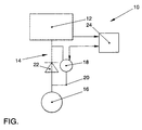
- the fuel delivery system 10 includes a fuel pump 12 that has a Pressure line system 14 is connected to a tank 16. Because of Clarity is more appropriate to the representation of the internal combustion engine Adjustment means for the fuel pump 12, such as a pressure regulator, are dispensed with been.
- an additional pump 18 is integrated, which is in a bypass 20 of the pressure line system 14 is housed and parallel to one Check valve 22 is located.
- the additional pump 18 blocks the bypass 20, and the promotion can only be carried out by the check valve 22 respectively. A backflow of the fuel through the bypass 20 is thus prevented.
- the fuel pump 12 and the auxiliary pump 18 are a control unit 24 assigned that directly or via known data lines Actuating means is connected to the auxiliary pump 18 and the fuel pump 12. About the Control unit 24, a delivery rate of the fuel pump 12 can be detected and the Additional pump 18 can be regulated depending on it.
- the auxiliary pump 18 can be switched to a sufficient To ensure fuel flow to the internal combustion engine. After the start of the Internal combustion engine, for example when a predetermined speed is reached the internal combustion engine, the auxiliary pump 18 can be switched off again. However, it is advantageous to have the auxiliary pump 18 in the acceleration phases of the motor vehicle connect to total the delivery rate of the fuel delivery system 10th to increase and thus allow a small design of the fuel pump 12.
Landscapes
- Engineering & Computer Science (AREA)
- Chemical & Material Sciences (AREA)
- Combustion & Propulsion (AREA)
- Mechanical Engineering (AREA)
- General Engineering & Computer Science (AREA)
- Electrical Control Of Air Or Fuel Supplied To Internal-Combustion Engine (AREA)
- Jet Pumps And Other Pumps (AREA)
- Control Of Vehicle Engines Or Engines For Specific Uses (AREA)
- Feeding And Controlling Fuel (AREA)
- Filling Or Discharging Of Gas Storage Vessels (AREA)
Abstract
Description
Claims (7)
- Kraftstofförderanlage für eine Verbrennungskraftmaschine eines Kraftfahrzeuges, mit einer Kraftstoffpumpe, die über ein Druckleitungssystem Kraftstoff aus einem Tank zur Verbrennungskraftmaschine fördert, dadurch gekennzeichnet, daß sich zwischen dem Tank (16) und der Kraftstoffpumpe (12) eine elektrische Zusatzpumpe (18) befindet, die parallel zu einem Rückschlagventil (22) in einem Bypass (20) des Druckleitungssytems (14) angeordnet ist.
- Kraftstofförderanlage nach einem der vorgehenden Ansprüche, dadurch gekennzeichnet, daß der Zusatzpumpe (18) und der Kraftstoffpumpe (12) ein Steuergerät (24) zugeordnet ist, über das eine Regelung einer Förderleistung der Zusatzpumpe (18) in Abhängigkeit von einer Förderleistung der Kraftstoffpumpe (12) erfolgt.
- Verfahren zum Betrieb einer Kraftstofförderanlage für eine Verbrennungskraftmaschine eines Kraftfahrzeuges, mit einer Kraftstoffpumpe, die über ein Druckleitungssystem Kraftstoff aus einem Tank zur Verbrennungskraftmaschine fördert und mit einer zwischen dem Tank und der Kraftstoffpumpe angeordneten elektrischen Zusatzpumpe, dadurch gekennzeichnet, daß eine Förderleistung der Kraftstoffpumpe (12) in einem Steuergerät (24) erfaßt wird und in Abhängigkeit davon eine Förderleistung der Zusatzpumpe (18) eingestellt wird.
- Verfahren nach Anspruch 3, dadurch gekennzeichnet, daß die Förderleistung der Kraftstoffpumpe (12) anhand einer Drehzahl der Verbrennungskraftmaschine abgeschätzt wird und hieraus eine Solleinspritzmenge abgeleitet wird.
- Verfahren nach Anspruch 3 oder 4, dadurch gekennzeichnet, daß die Förderleistung der Zusatzpumpe (18) in einer Startphase der Verbrennungskraftmaschine erhöht wird.
- Verfahren nach den Ansprüchen 3 oder 4, dadurch gekennzeichnet, daß die Förderleistung der Zusatzpumpe (18) in einer Beschleunigungsphase der Verbrennungskraftmaschine erhöht wird.
- Verfahren nach den Ansprüchen 3 oder 4, dadurch gekennzeichnet, daß in einer Leerlaufphase der Verbrennungskraftmaschine die Förderung über die Zusatzpumpe (18) erfolgt.
Applications Claiming Priority (2)
| Application Number | Priority Date | Filing Date | Title |
|---|---|---|---|
| DE19948149 | 1999-10-07 | ||
| DE19948149A DE19948149A1 (de) | 1999-10-07 | 1999-10-07 | Kraftstofförderanlage und Verfahren zum Betrieb der Kraftstofförderanlage |
Publications (3)
| Publication Number | Publication Date |
|---|---|
| EP1091115A2 true EP1091115A2 (de) | 2001-04-11 |
| EP1091115A3 EP1091115A3 (de) | 2001-12-05 |
| EP1091115B1 EP1091115B1 (de) | 2005-08-17 |
Family
ID=7924697
Family Applications (1)
| Application Number | Title | Priority Date | Filing Date |
|---|---|---|---|
| EP00119392A Expired - Lifetime EP1091115B1 (de) | 1999-10-07 | 2000-09-12 | Kraftstofförderanlage und Verfahren zum Betrieb der Kraftstofförderanlage |
Country Status (3)
| Country | Link |
|---|---|
| EP (1) | EP1091115B1 (de) |
| AT (1) | ATE302342T1 (de) |
| DE (2) | DE19948149A1 (de) |
Cited By (1)
| Publication number | Priority date | Publication date | Assignee | Title |
|---|---|---|---|---|
| RU2413631C2 (ru) * | 2005-11-29 | 2011-03-10 | Джи Эм Глоубал Текнолоджи Оперейшнз, Инк. | Топливный бак |
Families Citing this family (3)
| Publication number | Priority date | Publication date | Assignee | Title |
|---|---|---|---|---|
| DE10130352A1 (de) * | 2001-06-23 | 2003-01-02 | Bosch Gmbh Robert | Einspritzanlage für eine Brennkraftmaschine mit zwei Niederdruckpumpen |
| DE10360091A1 (de) * | 2003-12-20 | 2005-07-21 | Deutz Ag | Hubkolbenbrennkraftmaschine mit einer Hilfspumpe |
| CN114544071A (zh) * | 2022-02-28 | 2022-05-27 | 河北工程大学 | 一种膏体充填物料输送状态在线监测系统 |
Family Cites Families (9)
| Publication number | Priority date | Publication date | Assignee | Title |
|---|---|---|---|---|
| DE3013368A1 (de) * | 1980-04-05 | 1981-10-15 | Daimler-Benz Ag, 7000 Stuttgart | Regelung, insbesondere elektronische regelung fuer dieselmotoren |
| DE3707271C1 (de) * | 1987-03-06 | 1988-05-19 | Mannesmann Kienzle Gmbh | Ventilanordnung fuer einen Gasabscheider |
| DE3937709A1 (de) * | 1989-11-13 | 1991-05-16 | Bosch Gmbh Robert | Kraftstoffeinspritzpumpe fuer brennkraftmaschinen |
| US5598817A (en) * | 1993-09-10 | 1997-02-04 | Mitsubishi Jidosha Kogyo Kabushiki Kaisha | Fuel feeding system for internal combustion engine |
| JP3939779B2 (ja) * | 1995-05-26 | 2007-07-04 | ローベルト ボツシユ ゲゼルシヤフト ミツト ベシユレンクテル ハフツング | 内燃機関の燃料供給のための燃料供給装置 |
| DE19609922B4 (de) * | 1996-03-14 | 2005-09-15 | Robert Bosch Gmbh | Sekundärluftsystemdiagnoseverfahren |
| FR2751242B1 (fr) * | 1996-07-18 | 1998-09-25 | Filtrauto | Filtre a gazole pour moteur diesel et dispositif d'alimentation incluant un tel filtre |
| DE19648690A1 (de) * | 1996-11-25 | 1998-05-28 | Bosch Gmbh Robert | Kraftstoffeinspritzsystem |
| JP3708702B2 (ja) * | 1998-03-09 | 2005-10-19 | 三菱電機株式会社 | 高圧燃料ポンプのフィード圧脈動低減装置 |
-
1999
- 1999-10-07 DE DE19948149A patent/DE19948149A1/de not_active Withdrawn
-
2000
- 2000-09-12 DE DE50010959T patent/DE50010959D1/de not_active Expired - Fee Related
- 2000-09-12 EP EP00119392A patent/EP1091115B1/de not_active Expired - Lifetime
- 2000-09-12 AT AT00119392T patent/ATE302342T1/de not_active IP Right Cessation
Non-Patent Citations (1)
| Title |
|---|
| None |
Cited By (1)
| Publication number | Priority date | Publication date | Assignee | Title |
|---|---|---|---|---|
| RU2413631C2 (ru) * | 2005-11-29 | 2011-03-10 | Джи Эм Глоубал Текнолоджи Оперейшнз, Инк. | Топливный бак |
Also Published As
| Publication number | Publication date |
|---|---|
| DE50010959D1 (de) | 2005-09-22 |
| EP1091115A3 (de) | 2001-12-05 |
| ATE302342T1 (de) | 2005-09-15 |
| DE19948149A1 (de) | 2001-04-12 |
| EP1091115B1 (de) | 2005-08-17 |
Similar Documents
| Publication | Publication Date | Title |
|---|---|---|
| DE10213598B4 (de) | Ölpumpe für eine Brennkraftmaschine und Verfahren zum Betrieb derselben | |
| EP1126157B1 (de) | Kraftstoffversorgungseinrichtung für eine Brennkraftmaschine eines Kraftfahrzeugs | |
| EP1566536B1 (de) | Kraftstoffversorgungssystem und Verfahren zur Regelung der Kraftstoffversorgung | |
| DE3718607A1 (de) | Kraftstoffeinspritzpumpenanordnung | |
| DE102018220150A1 (de) | Pumpenmodul für Kühlmittel | |
| WO2011128163A1 (de) | Pumpenanordnung | |
| EP2093386A2 (de) | Gasturbinenlagerölsystem mit Ölrücklauf | |
| DE10003748A1 (de) | Kraftstoffversorgungssystem für Brennkraftmaschinen mit verbesserter Befüllung der Kraftstoffleitung | |
| DE102004008478B4 (de) | Fördermengenregelung einer Hochdruckpumpe | |
| DE102007062215A1 (de) | Verfahren zum Betreiben einer Brennkraftmaschine | |
| EP0974005B1 (de) | Kraftstoff-fördermodul für eine benzindirekteinspeisung einer brennkraftmaschine mit einem ventil | |
| DE19948149A1 (de) | Kraftstofförderanlage und Verfahren zum Betrieb der Kraftstofförderanlage | |
| DE102009014072B4 (de) | Common-Rail-Einspritzsystem sowie Verfahren zur Druckentlastung eines Common-Rail-Einspritzsystems | |
| DE19933569B4 (de) | Einspritzsystem für eine Brennkraftmaschine | |
| DE19937674B4 (de) | Einspritzanlage für eine Brennkraftmaschine | |
| DE102007051498A1 (de) | Kraftstoffzumesseinheit für ein Flugzeugtriebwerk | |
| DE102009028115A1 (de) | Kraftstoffeinspritzanlage und Verfahren zum Betreiben einer Kraftstoffeinspritzanlage | |
| DE102010011469B4 (de) | Kraftstoff-Zuführungseinrichtung für einen Motor | |
| DE10026373A1 (de) | Hochdruck-Kraftstoffeinspritzanlage für eine Brennkraftmaschine | |
| DE19501352B4 (de) | Brennstoffördereinrichtung mit Strahlpumpenanordnung | |
| DE102009061750B3 (de) | Schnellstart eines Common Rail-Systems | |
| DE10218900B4 (de) | Kraftfahrzeug-Heizgerät | |
| EP0656471A2 (de) | Vorrichtung zur Reduzierung der Kraftstofftemperatur im Tank eines Kraftfahrzeuges | |
| DE102009017892A1 (de) | Kraftstoffversorgungssystem | |
| DE102016225384A1 (de) | Kraftstofffördereinrichtung |
Legal Events
| Date | Code | Title | Description |
|---|---|---|---|
| PUAI | Public reference made under article 153(3) epc to a published international application that has entered the european phase |
Free format text: ORIGINAL CODE: 0009012 |
|
| AK | Designated contracting states |
Kind code of ref document: A2 Designated state(s): AT BE CH CY DE DK ES FI FR GB GR IE IT LI LU MC NL PT SE |
|
| AX | Request for extension of the european patent |
Free format text: AL;LT;LV;MK;RO;SI |
|
| PUAL | Search report despatched |
Free format text: ORIGINAL CODE: 0009013 |
|
| AK | Designated contracting states |
Kind code of ref document: A3 Designated state(s): AT BE CH CY DE DK ES FI FR GB GR IE IT LI LU MC NL PT SE |
|
| AX | Request for extension of the european patent |
Free format text: AL;LT;LV;MK;RO;SI |
|
| 17P | Request for examination filed |
Effective date: 20020605 |
|
| AKX | Designation fees paid |
Free format text: AT BE CH CY DE DK ES FI FR GB GR IE IT LI LU MC NL PT SE |
|
| 17Q | First examination report despatched |
Effective date: 20040517 |
|
| GRAP | Despatch of communication of intention to grant a patent |
Free format text: ORIGINAL CODE: EPIDOSNIGR1 |
|
| GRAS | Grant fee paid |
Free format text: ORIGINAL CODE: EPIDOSNIGR3 |
|
| GRAA | (expected) grant |
Free format text: ORIGINAL CODE: 0009210 |
|
| AK | Designated contracting states |
Kind code of ref document: B1 Designated state(s): AT BE CH CY DE DK ES FI FR GB GR IE IT LI LU MC NL PT SE |
|
| PG25 | Lapsed in a contracting state [announced via postgrant information from national office to epo] |
Ref country code: IT Free format text: LAPSE BECAUSE OF FAILURE TO SUBMIT A TRANSLATION OF THE DESCRIPTION OR TO PAY THE FEE WITHIN THE PRESCRIBED TIME-LIMIT;WARNING: LAPSES OF ITALIAN PATENTS WITH EFFECTIVE DATE BEFORE 2007 MAY HAVE OCCURRED AT ANY TIME BEFORE 2007. THE CORRECT EFFECTIVE DATE MAY BE DIFFERENT FROM THE ONE RECORDED. Effective date: 20050817 Ref country code: GB Free format text: LAPSE BECAUSE OF FAILURE TO SUBMIT A TRANSLATION OF THE DESCRIPTION OR TO PAY THE FEE WITHIN THE PRESCRIBED TIME-LIMIT Effective date: 20050817 Ref country code: IE Free format text: LAPSE BECAUSE OF FAILURE TO SUBMIT A TRANSLATION OF THE DESCRIPTION OR TO PAY THE FEE WITHIN THE PRESCRIBED TIME-LIMIT Effective date: 20050817 Ref country code: FI Free format text: LAPSE BECAUSE OF FAILURE TO SUBMIT A TRANSLATION OF THE DESCRIPTION OR TO PAY THE FEE WITHIN THE PRESCRIBED TIME-LIMIT Effective date: 20050817 Ref country code: NL Free format text: LAPSE BECAUSE OF FAILURE TO SUBMIT A TRANSLATION OF THE DESCRIPTION OR TO PAY THE FEE WITHIN THE PRESCRIBED TIME-LIMIT Effective date: 20050817 |
|
| REG | Reference to a national code |
Ref country code: GB Ref legal event code: FG4D Free format text: NOT ENGLISH |
|
| REG | Reference to a national code |
Ref country code: CH Ref legal event code: EP |
|
| PG25 | Lapsed in a contracting state [announced via postgrant information from national office to epo] |
Ref country code: CY Free format text: LAPSE BECAUSE OF FAILURE TO SUBMIT A TRANSLATION OF THE DESCRIPTION OR TO PAY THE FEE WITHIN THE PRESCRIBED TIME-LIMIT Effective date: 20050912 Ref country code: AT Free format text: LAPSE BECAUSE OF NON-PAYMENT OF DUE FEES Effective date: 20050912 |
|
| REG | Reference to a national code |
Ref country code: IE Ref legal event code: FG4D Free format text: LANGUAGE OF EP DOCUMENT: GERMAN |
|
| REF | Corresponds to: |
Ref document number: 50010959 Country of ref document: DE Date of ref document: 20050922 Kind code of ref document: P |
|
| PG25 | Lapsed in a contracting state [announced via postgrant information from national office to epo] |
Ref country code: MC Free format text: LAPSE BECAUSE OF NON-PAYMENT OF DUE FEES Effective date: 20050930 Ref country code: BE Free format text: LAPSE BECAUSE OF NON-PAYMENT OF DUE FEES Effective date: 20050930 Ref country code: CH Free format text: LAPSE BECAUSE OF NON-PAYMENT OF DUE FEES Effective date: 20050930 Ref country code: LI Free format text: LAPSE BECAUSE OF NON-PAYMENT OF DUE FEES Effective date: 20050930 |
|
| PG25 | Lapsed in a contracting state [announced via postgrant information from national office to epo] |
Ref country code: LU Free format text: LAPSE BECAUSE OF NON-PAYMENT OF DUE FEES Effective date: 20051017 |
|
| PG25 | Lapsed in a contracting state [announced via postgrant information from national office to epo] |
Ref country code: GR Free format text: LAPSE BECAUSE OF FAILURE TO SUBMIT A TRANSLATION OF THE DESCRIPTION OR TO PAY THE FEE WITHIN THE PRESCRIBED TIME-LIMIT Effective date: 20051117 Ref country code: SE Free format text: LAPSE BECAUSE OF FAILURE TO SUBMIT A TRANSLATION OF THE DESCRIPTION OR TO PAY THE FEE WITHIN THE PRESCRIBED TIME-LIMIT Effective date: 20051117 Ref country code: DK Free format text: LAPSE BECAUSE OF FAILURE TO SUBMIT A TRANSLATION OF THE DESCRIPTION OR TO PAY THE FEE WITHIN THE PRESCRIBED TIME-LIMIT Effective date: 20051117 |
|
| PG25 | Lapsed in a contracting state [announced via postgrant information from national office to epo] |
Ref country code: ES Free format text: LAPSE BECAUSE OF FAILURE TO SUBMIT A TRANSLATION OF THE DESCRIPTION OR TO PAY THE FEE WITHIN THE PRESCRIBED TIME-LIMIT Effective date: 20051128 |
|
| PG25 | Lapsed in a contracting state [announced via postgrant information from national office to epo] |
Ref country code: PT Free format text: LAPSE BECAUSE OF FAILURE TO SUBMIT A TRANSLATION OF THE DESCRIPTION OR TO PAY THE FEE WITHIN THE PRESCRIBED TIME-LIMIT Effective date: 20060117 |
|
| NLV1 | Nl: lapsed or annulled due to failure to fulfill the requirements of art. 29p and 29m of the patents act | ||
| GBV | Gb: ep patent (uk) treated as always having been void in accordance with gb section 77(7)/1977 [no translation filed] |
Effective date: 20050817 |
|
| REG | Reference to a national code |
Ref country code: IE Ref legal event code: FD4D |
|
| REG | Reference to a national code |
Ref country code: CH Ref legal event code: PL |
|
| PLBE | No opposition filed within time limit |
Free format text: ORIGINAL CODE: 0009261 |
|
| STAA | Information on the status of an ep patent application or granted ep patent |
Free format text: STATUS: NO OPPOSITION FILED WITHIN TIME LIMIT |
|
| 26N | No opposition filed |
Effective date: 20060518 |
|
| PG25 | Lapsed in a contracting state [announced via postgrant information from national office to epo] |
Ref country code: FR Free format text: LAPSE BECAUSE OF FAILURE TO SUBMIT A TRANSLATION OF THE DESCRIPTION OR TO PAY THE FEE WITHIN THE PRESCRIBED TIME-LIMIT Effective date: 20060818 |
|
| PGFP | Annual fee paid to national office [announced via postgrant information from national office to epo] |
Ref country code: DE Payment date: 20060930 Year of fee payment: 7 |
|
| EN | Fr: translation not filed | ||
| BERE | Be: lapsed |
Owner name: VOLKSWAGEN A.G. Effective date: 20050930 |
|
| PG25 | Lapsed in a contracting state [announced via postgrant information from national office to epo] |
Ref country code: DE Free format text: LAPSE BECAUSE OF NON-PAYMENT OF DUE FEES Effective date: 20080401 |
|
| PG25 | Lapsed in a contracting state [announced via postgrant information from national office to epo] |
Ref country code: FR Free format text: LAPSE BECAUSE OF FAILURE TO SUBMIT A TRANSLATION OF THE DESCRIPTION OR TO PAY THE FEE WITHIN THE PRESCRIBED TIME-LIMIT Effective date: 20050930 |
|
| PG25 | Lapsed in a contracting state [announced via postgrant information from national office to epo] |
Ref country code: FR Free format text: LAPSE BECAUSE OF FAILURE TO SUBMIT A TRANSLATION OF THE DESCRIPTION OR TO PAY THE FEE WITHIN THE PRESCRIBED TIME-LIMIT Effective date: 20050817 |