EP0974005B1 - Kraftstoff-fördermodul für eine benzindirekteinspeisung einer brennkraftmaschine mit einem ventil - Google Patents
Kraftstoff-fördermodul für eine benzindirekteinspeisung einer brennkraftmaschine mit einem ventil Download PDFInfo
- Publication number
- EP0974005B1 EP0974005B1 EP99934225A EP99934225A EP0974005B1 EP 0974005 B1 EP0974005 B1 EP 0974005B1 EP 99934225 A EP99934225 A EP 99934225A EP 99934225 A EP99934225 A EP 99934225A EP 0974005 B1 EP0974005 B1 EP 0974005B1
- Authority
- EP
- European Patent Office
- Prior art keywords
- fuel
- pressure
- valve
- supply module
- fuel supply
- Prior art date
- Legal status (The legal status is an assumption and is not a legal conclusion. Google has not performed a legal analysis and makes no representation as to the accuracy of the status listed.)
- Expired - Lifetime
Links
- 239000000446 fuel Substances 0.000 title claims description 91
- 238000002485 combustion reaction Methods 0.000 title claims description 14
- 239000003502 gasoline Substances 0.000 title description 6
- 238000002347 injection Methods 0.000 title description 2
- 239000007924 injection Substances 0.000 title description 2
- 239000012528 membrane Substances 0.000 description 7
- 239000000243 solution Substances 0.000 description 4
- 239000003638 chemical reducing agent Substances 0.000 description 2
- 238000010586 diagram Methods 0.000 description 2
- 239000002828 fuel tank Substances 0.000 description 2
- 238000000034 method Methods 0.000 description 2
- 230000001105 regulatory effect Effects 0.000 description 2
- 230000000694 effects Effects 0.000 description 1
Images

Classifications
-
- B—PERFORMING OPERATIONS; TRANSPORTING
- B60—VEHICLES IN GENERAL
- B60K—ARRANGEMENT OR MOUNTING OF PROPULSION UNITS OR OF TRANSMISSIONS IN VEHICLES; ARRANGEMENT OR MOUNTING OF PLURAL DIVERSE PRIME-MOVERS IN VEHICLES; AUXILIARY DRIVES FOR VEHICLES; INSTRUMENTATION OR DASHBOARDS FOR VEHICLES; ARRANGEMENTS IN CONNECTION WITH COOLING, AIR INTAKE, GAS EXHAUST OR FUEL SUPPLY OF PROPULSION UNITS IN VEHICLES
- B60K15/00—Arrangement in connection with fuel supply of combustion engines or other fuel consuming energy converters, e.g. fuel cells; Mounting or construction of fuel tanks
- B60K15/03—Fuel tanks
- B60K15/077—Fuel tanks with means modifying or controlling distribution or motion of fuel, e.g. to prevent noise, surge, splash or fuel starvation
-
- F—MECHANICAL ENGINEERING; LIGHTING; HEATING; WEAPONS; BLASTING
- F02—COMBUSTION ENGINES; HOT-GAS OR COMBUSTION-PRODUCT ENGINE PLANTS
- F02M—SUPPLYING COMBUSTION ENGINES IN GENERAL WITH COMBUSTIBLE MIXTURES OR CONSTITUENTS THEREOF
- F02M37/00—Apparatus or systems for feeding liquid fuel from storage containers to carburettors or fuel-injection apparatus; Arrangements for purifying liquid fuel specially adapted for, or arranged on, internal-combustion engines
- F02M37/04—Feeding by means of driven pumps
- F02M37/14—Feeding by means of driven pumps the pumps being combined with other apparatus
-
- F—MECHANICAL ENGINEERING; LIGHTING; HEATING; WEAPONS; BLASTING
- F02—COMBUSTION ENGINES; HOT-GAS OR COMBUSTION-PRODUCT ENGINE PLANTS
- F02M—SUPPLYING COMBUSTION ENGINES IN GENERAL WITH COMBUSTIBLE MIXTURES OR CONSTITUENTS THEREOF
- F02M69/00—Low-pressure fuel-injection apparatus ; Apparatus with both continuous and intermittent injection; Apparatus injecting different types of fuel
- F02M69/46—Details, component parts or accessories not provided for in, or of interest apart from, the apparatus covered by groups F02M69/02 - F02M69/44
- F02M69/462—Arrangement of fuel conduits, e.g. with valves for maintaining pressure in the pipes after the engine being shut-down
-
- F—MECHANICAL ENGINEERING; LIGHTING; HEATING; WEAPONS; BLASTING
- F02—COMBUSTION ENGINES; HOT-GAS OR COMBUSTION-PRODUCT ENGINE PLANTS
- F02M—SUPPLYING COMBUSTION ENGINES IN GENERAL WITH COMBUSTIBLE MIXTURES OR CONSTITUENTS THEREOF
- F02M69/00—Low-pressure fuel-injection apparatus ; Apparatus with both continuous and intermittent injection; Apparatus injecting different types of fuel
- F02M69/46—Details, component parts or accessories not provided for in, or of interest apart from, the apparatus covered by groups F02M69/02 - F02M69/44
- F02M69/54—Arrangement of fuel pressure regulators
Definitions
- the invention relates to a fuel delivery module for a gasoline direct feed an internal combustion engine of a motor vehicle.
- the fuel delivery module has an electric fuel pump and one with a pressure line the valve connected to the electric fuel pump.
- the valve has one first space, through the fuel from the pressure line to the internal combustion engine can flow there.
- Fuel delivery modules that are known work at a constant system pressure. Such a fuel delivery module can be seen, for example, from DE 42 42 242 A1.
- the electric fuel pump there is connected to a fuel supply line.
- the fuel flow flowing to this line is via a pressure regulator affected. This can serve as a reference value for regulating the ambient pressure take up.
- the pressure regulator allows that part of the fuel flow from the fuel supply line is returned to the electric fuel pump, for example with With the help of a suction jet pump. This way, the fuel delivery module ensures that there is always a constant system pressure.
- a fuel delivery module is not is operated with a constant system pressure. Rather, the System pressure electronically controlled.
- the electric fuel pump is equipped with a control unit connected, which in turn from the fuel supply line by means of a Pressure sensor receives information about the fuel flow. Controls via a clock module the control unit turns on the electric fuel pump and changes the speed of the Electric fuel pump able to adjust the pressure in the fuel delivery module to the need adapt.
- a fuel pressure regulator which has a valve between the Has fuel inlet and the fuel outlet, and two membranes. One of the Two membranes can be pressurized with compressed air to increase pressure.
- a pressure control valve which is adjustable depending on the load Has spring element. This spring element controls the valve opening force in dependence from the load.
- EP 0 585 810 A there is also a pressure regulator with a main housing and a secondary housing known, the main housing having an inlet and an outlet as well is provided with a valve seat arranged between the inlet and outlet, and wherein the secondary housing attached to the main housing carries a regulator spring and between there is a diaphragm valve arrangement in the housing, which comprises a ball valve 80.
- US 5 706 785 A is a fuel supply system for an internal combustion engine known.
- This fuel supply system includes a fuel tank a fuel pump, a fuel pressure regulator and a pressure reducer, the Pressure reducer is arranged downstream behind the fuel pressure regulator.
- the fuel delivery module according to the invention for a gasoline direct feed the one Electric fuel pump and one connected to a pressure line of the electric fuel pump Has valve with a first space, wherein fuel from the pressure line can flow to the internal combustion engine has a fuel pressure regulator as a valve.
- This fuel pressure regulator creates an additional pressure in the first Room.
- the fuel delivery module succeeds when the internal combustion engine starts for gasoline direct injection over a certain period of time Can apply start pressure. In the subsequent operating state, this is increased However, starting pressure is no longer necessary and can be relaxed. In this way it is System pressure can be adapted to the respective requirements of the fuel delivery module. Farther this solution is extremely compact and required due to the few necessary components therefore very little space in the tank area.
- This solution also eliminates one technically more complex control of the electric fuel pump, so that the structure of the Fuel delivery module can be simplified and carried out more cost-effectively.
- this solution is again from the start with less possible sources of interference, whereby by building the fuel delivery module a modular principle, the respective components can be checked more easily.
- this solution allows to use components that are known and mature are. This enables the development effort for the fuel delivery module to be achieved to be able to keep low.
- a diaphragm valve is preferred as the fuel pressure regulator used. This has a first and a second room. By doing Now if a pressure is generated in the second room, it will also be imprinted in the first room and in this way creates additional pressure in the fuel delivery module.
- the diaphragm valve are also other components can be used, which are able to withstand the pressure in the first room additionally increase or decrease, for example, via a cylinder or similar.
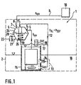
- the fuel delivery module 1 shows a fuel delivery module 1 which can be used to increase the starting pressure in a gasoline direct feed.
- the fuel delivery module 1 is arranged in a tank 2.
- the fuel delivery module 1 has an electric fuel pump 3.
- a pressure line 4 runs from the electric fuel pump 3 to a diaphragm valve 5, the pressure line 4 opening into the first space 7 of the diaphragm valve 5 at an inlet 6.
- Via a first outlet 8 a fuel flow can flow from the first space 7 via a fuel feed line 9 to an internal combustion engine 10 with a gasoline direct feed.
- the system pressure p sys applied by the electric fuel pump 3 prevails.
- fuel is drawn in by a regulated suction jet pump 13 via a fuel return line 12.
- the suction jet pump 13 which is controlled by means of a control valve 14, also sucks fuel 16 from a bottom region of the tank 2 when the fuel is returned from the fuel return line 12 to a reservoir 15 of the fuel delivery module 1.
- the electric fuel pump 3 then in turn sucks in the fuel that flows into the pressure line 4 from the reservoir 15.
- a branch 17 runs from the fuel return line 12 to an on-off valve 18.
- the on-off valve 18 is in turn connected via a first connection 19 to a second space 20 of the diaphragm valve 5. Furthermore, the second space 20 has a second connection 21, to which a pressure relief line 22 is connected.
- a throttle 23 is in turn located in the pressure relief line.
- This throttle 23 and thus the second connection 21 can be closed in a controlled manner or opens in dependence on a control system (not shown here).
- the membrane valve 5 also has a spiral spring 25. This is arranged in the second space 20 and supports the membrane 24 in its effect.
- the membrane valve 5 with membrane 24 and coil spring 25 controls the system pressure p sys with these means during the normal operating state of the running internal combustion engine. However, if this is started, an additional pressure is generated in the first space 7 by the on-off valve 18 the pressure p RL from the fuel return line 12, which is also the suction pressure p SSP of the suction jet pump 13, via the first connection 19 in the second Space 20 on the spring side of the diaphragm valve 5 additionally impresses.
- FIG. 2 shows an embodiment of the fuel delivery module 1, in which the additional pressure is not generated by a suction jet pump. Rather, this is done via a pressure generating device 26, which is connected to the on-off valve 18 connected.
- the pressure generating device 26 can be a pump 27 or a low or high pressure circuit line 28 of the motor vehicle his. Both alternatives are shown in dashed lines.
- the on-off valve 18 is connected to a control device 30 via a first line 29.
- the Control unit 30 is part of an engine control 31, which has a second Line 32 is connected to the internal combustion engine 10.
- the throttle 23 in turn is also connected to the control unit 30 via a third line 33 connected.
- the on-off valve 18 can be electrical, pneumatic, hydraulic, mechanical or other Ways are actuated, the control impulses depending on different Engine parameters such as temperature, fuel, air pressure, etc. can.
- the use of a timing element 34 is also possible, which is indicated by dashed lines.
- the timer 34 for example activates and releases suitable control pulses when turning an ignition key for the throttle 23 or the on-off valve 26 from. That way too it is possible that the on-off valve 18 again after the starting process is closed to the lower operating pressure by reducing the additional pressure to achieve via the throttle 23.
Landscapes
- Engineering & Computer Science (AREA)
- Chemical & Material Sciences (AREA)
- Combustion & Propulsion (AREA)
- Mechanical Engineering (AREA)
- General Engineering & Computer Science (AREA)
- Life Sciences & Earth Sciences (AREA)
- Sustainable Development (AREA)
- Sustainable Energy (AREA)
- Transportation (AREA)
- Fuel-Injection Apparatus (AREA)
- Electrical Control Of Air Or Fuel Supplied To Internal-Combustion Engine (AREA)
Description
- Fig. 1
- eine Prinzipskizze eines besonders bevorzugten Kraftstoff-Fördermoduls gemäß der Erfindung unter Verwendung einer Saugstrahlpumpe; und
- Fig. 2
- eine weitere Prinzipskizze, die einen vereinfachten Aufbau des Kraftstoff-Fördermoduls aufzeigt.
Claims (12)
- Kraftstoff-Fördermodul (1) für eine Benzindirekteinspeisung einer Brennkraftmaschine (10) eines Kraftfahrzeuges, aufweisend eine Elektrokraftstoffpumpe (3) und ein mit einer Druckleitung (4) der Elektrokraftstoffpumpe (3) verbundenes Ventil (5) mit einem ersten Raum (7), durch den Kraftstoff (16) von der Druckleitung zur Brennkraftmaschine (10) hin strömen kann, dadurch gekennzeichnet, dass das Ventil (5) ein Kraftstoffdruckregler ist, der einen Zusatzdruck (Δp) in dem ersten Raum (7) erzeugt, und dass der Kraftstoffdruckregler zwischen der Elektrokraftstoffpumpe (3) und der Brennkraftmaschine (10) angeordnet ist.
- Kraftstoff-Fördermodul (1) nach Anspruch 1, dadurch gekennzeichnet, daß der Kraftstoffdruckregler ein Membranventil (5) ist.
- Kraftstoff-Fördermodul (1) nach Anspruch 1 oder 2, dadurch gekennzeichnet, daß das Ventil (5) einen ersten Anschluß (19) zur Aufbringung des Zusatzdruckes (Δp) hat.
- Kraftstoff-Fördermodul (1) nach Anspruch 1, 2 oder 3, dadurch gekennzeichnet, daß ein Ein-Aus-Ventil (18) den Zusatzdruck (Δp) steuert.
- Kraftstoff-Fördermodul (1) nach Anspruch 4, dadurch gekennzeichnet, daß das Ein-Aus-Ventil (18) mit einem Steuergerät (30) verbunden ist.
- Kraftstoff-Fördermodul (1) nach Anspruch 4, dadurch gekennzeichnet, daß das Steuergerät (30) eine Motorsteuerung (31) ist.
- Kraftstoff-Fördermodul (1) nach einem der vorhergehenden Ansprüche, dadurch gekennzeichnet, daß eine Pumpe (27) zur Erzeugung des Zusatzdrucks (Δp) angeschlossen ist.
- Kraftstoff-Fördermodul (1) nach einem der Ansprüche 1 bis 6, dadurch gekennzeichnet, daß der Kraftstoffdruckregler eine Verbindung zu einem Nieder- oder Hochdruckkreislauf (28) hat.
- Kraftstoff-Fördermodul (1) nach einem der vorhergehenden Ansprüche, dadurch gekennzeichnet, daß das Ventil (5) einen zweiten Anschluß (21) als Auslaß hat.
- Kraftstoff-Fördermodul (1) nach Anspruch 9, dadurch gekennzeichnet, daß an dem zweiten Anschluß (21) eine Drossel (23) angeordnet ist.
- Kraftstoff-Fördermodul (1) nach Anspruch 9 oder 10, dadurch gekennzeichnet, daß der zweite Anschluß (21) gesteuert verschließbar ist.
- Kraftstoff-Fördermodul (1) nach einem der vorhergehenden Ansprüche, dadurch gekennzeichnet, daß das Ventil (5) ein mit einer Spiralfeder (25) in einem zweiten Raum (20) unterstütztes Membranventil (5) ist, wobei im zweiten Raum (5) der erste (19) und der zweite (21) Anschluß münden.
Applications Claiming Priority (3)
| Application Number | Priority Date | Filing Date | Title |
|---|---|---|---|
| DE19805070A DE19805070C2 (de) | 1998-02-09 | 1998-02-09 | Kraftstoff-Fördermodul für eine Benzindirekteinspeisung einer Brennkraftmaschine mit einem Ventil |
| DE19805070 | 1998-02-09 | ||
| PCT/DE1999/000110 WO1999040313A1 (de) | 1998-02-09 | 1999-01-19 | Kraftstoff-fördermodul für eine benzindirekteinspeisung einer brennkraftmaschine mit einem ventil |
Publications (2)
| Publication Number | Publication Date |
|---|---|
| EP0974005A1 EP0974005A1 (de) | 2000-01-26 |
| EP0974005B1 true EP0974005B1 (de) | 2003-08-27 |
Family
ID=7857065
Family Applications (1)
| Application Number | Title | Priority Date | Filing Date |
|---|---|---|---|
| EP99934225A Expired - Lifetime EP0974005B1 (de) | 1998-02-09 | 1999-01-19 | Kraftstoff-fördermodul für eine benzindirekteinspeisung einer brennkraftmaschine mit einem ventil |
Country Status (4)
| Country | Link |
|---|---|
| EP (1) | EP0974005B1 (de) |
| JP (1) | JP2001520721A (de) |
| DE (2) | DE19805070C2 (de) |
| WO (1) | WO1999040313A1 (de) |
Families Citing this family (10)
| Publication number | Priority date | Publication date | Assignee | Title |
|---|---|---|---|---|
| DE10127834A1 (de) | 2001-06-08 | 2002-12-12 | Bosch Gmbh Robert | Vorrichtung und Verfahren zur Dosierung eines Reduktionsmittels zur Entfernung von Stickoxiden aus Abgasen |
| DE10129437A1 (de) * | 2001-06-19 | 2003-01-02 | Bosch Gmbh Robert | Kraftstoffversorgungseinrichtung für ein Kraftfahrzeug |
| DE10143892A1 (de) * | 2001-09-07 | 2003-03-27 | Pierburg Gmbh | Vorducksteueranordnung |
| DE10143891A1 (de) * | 2001-09-07 | 2003-03-27 | Pierburg Gmbh | Druckregelanordnung |
| US6712037B2 (en) * | 2002-01-09 | 2004-03-30 | Visteon Global Technologies, Inc. | Low pressure direct injection engine system |
| DE102004007878A1 (de) * | 2004-02-18 | 2005-09-15 | Ti Automotive (Neuss) Gmbh | Kraftstoffversorgungssystem und Verfahren zur Regelung der Kraftstoffversorgung |
| DE102004020941B9 (de) * | 2004-04-28 | 2006-05-04 | Pierburg Gmbh | Druckregelanordnung |
| DE102005036188A1 (de) * | 2005-08-02 | 2007-02-08 | Robert Bosch Gmbh | Kraftstoffversorgunssystem |
| DE102010044468A1 (de) * | 2010-09-06 | 2012-03-08 | Albonair Gmbh | Reduktionsmitteldosiersystem zur Eindüsung eines Reduktionsmittels in den Abgasstrom eines Verbrennungsmotors |
| US11754028B2 (en) * | 2021-06-23 | 2023-09-12 | Ford Global Technologies, Llc | Fuel system diaphragm valve |
Family Cites Families (6)
| Publication number | Priority date | Publication date | Assignee | Title |
|---|---|---|---|---|
| GB2070802B (en) * | 1980-01-31 | 1984-08-22 | Nissan Motor | Control of fuel supply to an ic engine |
| US4543935A (en) * | 1984-08-21 | 1985-10-01 | Walbro Corporation | Pressure regulator with variable response |
| JPH02136561A (ja) * | 1988-11-17 | 1990-05-25 | Yamaha Motor Co Ltd | 内燃機関の燃料噴射装置 |
| US5279327A (en) * | 1992-08-31 | 1994-01-18 | Orbital Walbro Corporation | Pressure regulator |
| DE4242242C2 (de) * | 1992-12-15 | 2003-04-30 | Bosch Gmbh Robert | Vorrichtung zum Versorgen der Brennkraftmaschine eines Kraftfahrzeuges mit in einem Vorratstank vorhandenem Kraftstoff |
| DE19510497A1 (de) * | 1995-03-23 | 1996-09-26 | Pierburg Gmbh | Brennstoffversorgungssystem für Brennkraftmaschinen |
-
1998
- 1998-02-09 DE DE19805070A patent/DE19805070C2/de not_active Expired - Fee Related
-
1999
- 1999-01-19 WO PCT/DE1999/000110 patent/WO1999040313A1/de not_active Ceased
- 1999-01-19 EP EP99934225A patent/EP0974005B1/de not_active Expired - Lifetime
- 1999-01-19 JP JP53983299A patent/JP2001520721A/ja active Pending
- 1999-01-19 DE DE59906747T patent/DE59906747D1/de not_active Expired - Fee Related
Also Published As
| Publication number | Publication date |
|---|---|
| DE59906747D1 (de) | 2003-10-02 |
| DE19805070C2 (de) | 1999-11-25 |
| EP0974005A1 (de) | 2000-01-26 |
| DE19805070A1 (de) | 1999-08-12 |
| WO1999040313A1 (de) | 1999-08-12 |
| JP2001520721A (ja) | 2001-10-30 |
Similar Documents
| Publication | Publication Date | Title |
|---|---|---|
| DE4231731C2 (de) | Auf Druck ansprechendes Kraftstoffzuführsystem | |
| DE69027829T2 (de) | Druckgesteuerte Kraftstoffördervorrichtung | |
| DE1122326B (de) | Vorrichtung fuer Niederdruck-Kraftstoffeinspritzung | |
| DE3126393A1 (de) | Kraftstoffeinspritzanlage fuer einen dieselmotor | |
| DE3603808A1 (de) | Elektronisches und mechanisches brennstoffeingabesystem | |
| DE68910065T2 (de) | System für die Steuerung der Kraftstoffzufuhr in einer Hochdruckeinspritzdüse. | |
| DE19961755A1 (de) | Kraftstoff-Zuführvorrichtung | |
| EP0974005B1 (de) | Kraftstoff-fördermodul für eine benzindirekteinspeisung einer brennkraftmaschine mit einem ventil | |
| DE3718607A1 (de) | Kraftstoffeinspritzpumpenanordnung | |
| DE3628815A1 (de) | Brennstoffsystem fuer ein gasturbinentriebwerk | |
| DE10222693B4 (de) | Verfahren und System zum Steuern der Kraftstoffeinspritzung | |
| EP1068435B1 (de) | Kraftstoffversorgungssystem für eine brennkraftmaschine insbesondere eines kraftfahrzeugs | |
| DE4443836A1 (de) | Einrichtung zur Kraftstoffversorgung für eine Brennkraftmaschine | |
| EP0483301B1 (de) | Kraftstoffversorgungssystem für eine brennkraftmaschine | |
| EP0185183A2 (de) | Elektronisch gesteuertes Kraftstoffeinspritzsystem für eine Brennkraftmaschine | |
| DE69507318T2 (de) | Brennstoffzufuhrvorrichtung mit druckregelung für fahrzeuge | |
| DE69020029T2 (de) | Einrichtung zur Kraftstoff-Einspritzung für einen elektronisch gesteuerten Brennkraftmotor. | |
| DE3516456A1 (de) | Kraftstoffeinspritzpumpe fuer brennkraftmaschinen | |
| DE69610442T2 (de) | Fahrzeuggeschwindigkeitsbegrenzungssystem | |
| DE10335698A1 (de) | Kraftstoffversorgungsanlage einer Brennkraftmaschine sowie Betriebsverfahren hierfür | |
| DE19946908A1 (de) | Verfahren zum Abbau des Rail-Drucks in einem Common-Rail-System für Brennkraftmaschinen | |
| WO2000011342A1 (de) | Verfahren zum schnellen aufbau des kraftstoffdruckes in einem kraftstoffspeicher | |
| DE10324958B4 (de) | Verfahren und Vorrichtung zum Betreiben einer Brennkraftmaschine eines Fahrzeugs | |
| EP0191930B1 (de) | Kraftstoffeinspritzpumpe für Brennkraftmaschinen | |
| DE69227044T2 (de) | Wasserzufuhr in einer brennkraftmaschine |
Legal Events
| Date | Code | Title | Description |
|---|---|---|---|
| PUAI | Public reference made under article 153(3) epc to a published international application that has entered the european phase |
Free format text: ORIGINAL CODE: 0009012 |
|
| 17P | Request for examination filed |
Effective date: 19991109 |
|
| AK | Designated contracting states |
Kind code of ref document: A1 Designated state(s): DE FR IT |
|
| 17Q | First examination report despatched |
Effective date: 20020226 |
|
| RTI1 | Title (correction) |
Free format text: FUEL SUPPLY MODULE WITH A VALVE FOR GASOLINE DIRECT INJECTION IN AN INTERNAL COMBUSTION ENGINE |
|
| GRAH | Despatch of communication of intention to grant a patent |
Free format text: ORIGINAL CODE: EPIDOS IGRA |
|
| GRAH | Despatch of communication of intention to grant a patent |
Free format text: ORIGINAL CODE: EPIDOS IGRA |
|
| GRAA | (expected) grant |
Free format text: ORIGINAL CODE: 0009210 |
|
| AK | Designated contracting states |
Designated state(s): DE FR IT |
|
| REF | Corresponds to: |
Ref document number: 59906747 Country of ref document: DE Date of ref document: 20031002 Kind code of ref document: P |
|
| ET | Fr: translation filed | ||
| PLBE | No opposition filed within time limit |
Free format text: ORIGINAL CODE: 0009261 |
|
| STAA | Information on the status of an ep patent application or granted ep patent |
Free format text: STATUS: NO OPPOSITION FILED WITHIN TIME LIMIT |
|
| 26N | No opposition filed |
Effective date: 20040528 |
|
| PGFP | Annual fee paid to national office [announced via postgrant information from national office to epo] |
Ref country code: FR Payment date: 20060119 Year of fee payment: 8 |
|
| PGFP | Annual fee paid to national office [announced via postgrant information from national office to epo] |
Ref country code: DE Payment date: 20070313 Year of fee payment: 9 |
|
| REG | Reference to a national code |
Ref country code: FR Ref legal event code: ST Effective date: 20070930 |
|
| PG25 | Lapsed in a contracting state [announced via postgrant information from national office to epo] |
Ref country code: FR Free format text: LAPSE BECAUSE OF NON-PAYMENT OF DUE FEES Effective date: 20070131 |
|
| PGFP | Annual fee paid to national office [announced via postgrant information from national office to epo] |
Ref country code: IT Payment date: 20080126 Year of fee payment: 10 |
|
| PG25 | Lapsed in a contracting state [announced via postgrant information from national office to epo] |
Ref country code: DE Free format text: LAPSE BECAUSE OF NON-PAYMENT OF DUE FEES Effective date: 20080801 |
|
| PG25 | Lapsed in a contracting state [announced via postgrant information from national office to epo] |
Ref country code: IT Free format text: LAPSE BECAUSE OF NON-PAYMENT OF DUE FEES Effective date: 20090119 |