EP1090713B1 - Fräshilfe mit einer Handoberfräse - Google Patents
Fräshilfe mit einer Handoberfräse Download PDFInfo
- Publication number
- EP1090713B1 EP1090713B1 EP99120105A EP99120105A EP1090713B1 EP 1090713 B1 EP1090713 B1 EP 1090713B1 EP 99120105 A EP99120105 A EP 99120105A EP 99120105 A EP99120105 A EP 99120105A EP 1090713 B1 EP1090713 B1 EP 1090713B1
- Authority
- EP
- European Patent Office
- Prior art keywords
- base
- milling
- router
- base body
- template
- Prior art date
- Legal status (The legal status is an assumption and is not a legal conclusion. Google has not performed a legal analysis and makes no representation as to the accuracy of the status listed.)
- Expired - Lifetime
Links
- 230000003068 static effect Effects 0.000 claims description 2
- 238000003801 milling Methods 0.000 description 41
- MOVRNJGDXREIBM-UHFFFAOYSA-N aid-1 Chemical compound O=C1NC(=O)C(C)=CN1C1OC(COP(O)(=O)OC2C(OC(C2)N2C3=C(C(NC(N)=N3)=O)N=C2)COP(O)(=O)OC2C(OC(C2)N2C3=C(C(NC(N)=N3)=O)N=C2)COP(O)(=O)OC2C(OC(C2)N2C3=C(C(NC(N)=N3)=O)N=C2)COP(O)(=O)OC2C(OC(C2)N2C(NC(=O)C(C)=C2)=O)COP(O)(=O)OC2C(OC(C2)N2C3=C(C(NC(N)=N3)=O)N=C2)COP(O)(=O)OC2C(OC(C2)N2C3=C(C(NC(N)=N3)=O)N=C2)COP(O)(=O)OC2C(OC(C2)N2C3=C(C(NC(N)=N3)=O)N=C2)COP(O)(=O)OC2C(OC(C2)N2C(NC(=O)C(C)=C2)=O)COP(O)(=O)OC2C(OC(C2)N2C3=C(C(NC(N)=N3)=O)N=C2)COP(O)(=O)OC2C(OC(C2)N2C3=C(C(NC(N)=N3)=O)N=C2)COP(O)(=O)OC2C(OC(C2)N2C3=C(C(NC(N)=N3)=O)N=C2)COP(O)(=O)OC2C(OC(C2)N2C(NC(=O)C(C)=C2)=O)COP(O)(=O)OC2C(OC(C2)N2C3=C(C(NC(N)=N3)=O)N=C2)COP(O)(=O)OC2C(OC(C2)N2C3=C(C(NC(N)=N3)=O)N=C2)COP(O)(=O)OC2C(OC(C2)N2C3=C(C(NC(N)=N3)=O)N=C2)CO)C(O)C1 MOVRNJGDXREIBM-UHFFFAOYSA-N 0.000 description 7
- 238000000034 method Methods 0.000 description 2
- XAGFODPZIPBFFR-UHFFFAOYSA-N aluminium Chemical compound [Al] XAGFODPZIPBFFR-UHFFFAOYSA-N 0.000 description 1
- 229910052782 aluminium Inorganic materials 0.000 description 1
- 239000000463 material Substances 0.000 description 1
- 239000004033 plastic Substances 0.000 description 1
- 229920003023 plastic Polymers 0.000 description 1
- 239000010875 treated wood Substances 0.000 description 1
Images
Classifications
-
- B—PERFORMING OPERATIONS; TRANSPORTING
- B27—WORKING OR PRESERVING WOOD OR SIMILAR MATERIAL; NAILING OR STAPLING MACHINES IN GENERAL
- B27C—PLANING, DRILLING, MILLING, TURNING OR UNIVERSAL MACHINES FOR WOOD OR SIMILAR MATERIAL
- B27C5/00—Machines designed for producing special profiles or shaped work, e.g. by rotary cutters; Equipment therefor
- B27C5/10—Portable hand-operated wood-milling machines; Routers
-
- B—PERFORMING OPERATIONS; TRANSPORTING
- B23—MACHINE TOOLS; METAL-WORKING NOT OTHERWISE PROVIDED FOR
- B23Q—DETAILS, COMPONENTS, OR ACCESSORIES FOR MACHINE TOOLS, e.g. ARRANGEMENTS FOR COPYING OR CONTROLLING; MACHINE TOOLS IN GENERAL CHARACTERISED BY THE CONSTRUCTION OF PARTICULAR DETAILS OR COMPONENTS; COMBINATIONS OR ASSOCIATIONS OF METAL-WORKING MACHINES, NOT DIRECTED TO A PARTICULAR RESULT
- B23Q9/00—Arrangements for supporting or guiding portable metal-working machines or apparatus
- B23Q9/0014—Portable machines provided with or cooperating with guide means supported directly by the workpiece during action
Definitions
- the present invention relates to a milling aid with a Hand router against unintentional tipping of the Router during the milling process.
- the present invention is therefore based on the object Propose milling aid at which the milling process is much easier.
- the milling aid then has a circular base body with the same thickness as the template. At the edge of this base body there is a recess at least at one point, the depth of which must be at least as great as the copying sleeve, which is located concentrically to the milling tool on the underside of the milling table.
- the recess is curved towards the center of the base body, the radius of the curvature corresponding to the outer radius of the copying sleeve.
- the recess in the base body is designed such that it has the shape of a segment of a circle and is two-stage.
- the recess with the smaller radius which corresponds approximately to the size of the inner radius of the copying sleeve, extends over the entire thickness of the base body.
- the second part of the also radial recess is slightly larger than the outer radius of the copying sleeve and at least so deep that the copying sleeve does not stand up at the bottom of the recess.
- a pipe segment serving as a holding element is fastened in this way, preferably by means of a screw that its outer curvature is tight against the smaller radius of the recess.
- the length of the pipe segment corresponds to the thickness of the Body.
- milling aids with an at least partially circular green body such as, for example, an elliptical or semicircular base
- Workpiece-facing side This ensures that the milling aid can slide on the workpiece while it adheres to the underside of the milling table. If the milling aid touches the inner edge of the template during the milling process, it swivels out of the corner area as in the other embodiments.
- more effort is required than in the previously described embodiments. In order to keep this effort to a minimum, both surfaces and the edge of the milling aid are highly slidable in the circular designs, which is achieved using materials such as aluminum, plastics or treated wood.
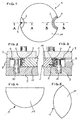
- the milling aid designated overall by 1, has one at least partially circular base body 11, the has the same thickness as the template 8 and a recess 2 with a radius of approximately the same size as that of the copying sleeve 6.
- FIG. 2 shows the milling table 7 of a router, not shown, which rests on one side on the milling aid 1 and on the other on a template 8.
- the copying sleeve 6 attached to the milling table 7 slides along the edge of the template 8 during the milling process and at the same time engages in the recess 2, where it engages behind the pin 4.
- the milling table 7 thus has a constant one Rest on the milling aid 1, causing the router to tip over is avoided.
- a pipe segment 3 is shown, which means a screw 5 in the recess 2 on the base body 11 is attached.
- the Kopierhülse6 engages behind the pipe segment 3, whose outer radius corresponds to the inner radius of the copying sleeve 6
- the copying sleeve 6 sits between the upper one Stage of the recess 2 and the pipe segment 3 that a perfect Turn the milling aid 1 around the copying sleeve 6
- the contact between milling tool 10 and Milling aid 1 is excluded here is processed without any problems.
Landscapes
- Engineering & Computer Science (AREA)
- Mechanical Engineering (AREA)
- Life Sciences & Earth Sciences (AREA)
- Wood Science & Technology (AREA)
- Forests & Forestry (AREA)
- Milling Processes (AREA)
- Adjustment And Processing Of Grains (AREA)
- Gripping Jigs, Holding Jigs, And Positioning Jigs (AREA)
Description
Die Länge des Stiftes ist etwa so groß,daß sein Ende in einer Ebene mit der Fläche des Grundkörpers liegt.Die so gestaltete Ausnehmung gewährleistet,daß die Fräshilfe,die mit der Seite,die die durchgehende Kreisfläche aufweist, auf dem Werkstück aufliegt,während des Fräsvorgangs einerseits zwischen Frästischunterseite und Werkstück befindlich mitbewegt wird,andererseits beim Berühren des Schabloneninnenrandes anfängt sich um die Kopierhülse zu drehen.
Der zweite Teil der ebenfalls radienförmigen Ausnehmung ist geringfügig größer als der Außenradius der Kopierhülse und geringstens so tief,daß die Kopierhülse am Grund der Ausnehmung nicht aufsteht.In dem Teil der Ausnehmung mit dem kleineren Radius ist ein als Halteelement dienendes Rohrsegment derart befestigt,vorzugsweise mittels einer Schraube,daß dessen äußere Wölbung fest am kleineren Radius der Ausnehmung anliegt.
Hierdurch wird erreicht,daß die Fräshilfe auf dem Werkstück gleiten kann,während sie an der Unterseite des Frästisches haftet.
Berührt die Fräshilfe beim Fräsvorgang den Innenrand der Schablone,schwenkt sie wie bei den anderen Ausführungsformen aus dem Eckbereich.
Es ist jedoch ein größerer Kraftaufwand erforderlich als bei vorher beschriebenen Ausführungsformen.
Um diesen Kraftaufwand minimal zu halten,sind bei den kreisförmigen Ausgestaltungen sowohl beide Flächen als auch der Rand der Fräshilfe hoch gleitfähig,was unter Verwendung von Materialien wie Aluminium,Kunststoffen oder behandeltem Holz erreicht wird.
- Fig.1
- eine Draufsicht der Fräshilfe ohne Werkstück und Oberfräse und Schablone
- Fig.2
- eine schematische Querschnittdarstellung der Fräshilfe mit Schablone,Oberfräse und Werkstück entlang der Linie A-A gemäß der Fig.1
- Fig.3
- eine schematische Querschnittdarstellung der Fräshilfe mit Schablone,Oberfräse und Werkstück entlang der Linie B-B gemäß der Fig.1
- Fig.4
- und Fig.5 zwei Fräshilfen mit teilweisen kreisförmigem Grundkörper.
Die am Frästisch 7 befestigte Kopierhülse 6 gleitet während des Fräsvorganges am Rand der Schablone 8 entlang und greift zugleich in die Ausnehmung 2,wo sie den Stift 4 hintergreift.
Bei Berührung des so gestalteten Grundkörpers 11 mit der Schablone 8 ,dreht sich die Fräshilfe 1 um die Kopierhülse 6 und schwnkt dabei aus dem Eckbereich der Schablone 8.
Claims (4)
- Fräshilfe mit einer Handoberfräse mit einer Schablone (8) gegen unbeabsichtigtes Abkippen der Oberfräse, mit einem mindestens teilweisen kreisförmigen Grundkörper (11) mit derselben Dicke wie die Schablone (8), wobei eine das Fräswerkzeug umgebende Kopierhülse (6) der Handoberfräse an der Schablone (8) entlang geführt wird, eine die Kopierhülse (6) derart aufnehmende, zur Mitte des Grundkörpers (11) hin gewölbte Ausnehmung (2), daß die Kopierhülse (6) ein an dem Grundkörper (11) im Bereich der Ausnehmung (2) angeordnetes Halteelement (3,4) hintergreift und eine sämtliche Seiten des Grundkörpers (11) betreffende hochgleitfähige Oberfläche.
- Vorrichtung nach Anspruch 1, dadurch gekennzeichnet, daß die Fläche des Grundkörpers (11) als Vollkreis ausgebildet ist.
- Vorrichtung nach Anspruch 1, dadurch gekennzeichnet, daß der Grundkörper (11) elipsen-, kreissegment-, ring-, oder sichelförmig ausgebildet ist.
- Vorrichtung nach Anspruch 3, dadurch gekennzeichnet, daß die dem Frästisch (7) zugewandte Seite des Grundkörpers (11) eine höhere Haftreibung aufweist als die dem Werkstück (9) zugewandte Seite.
Priority Applications (3)
| Application Number | Priority Date | Filing Date | Title |
|---|---|---|---|
| EP99120105A EP1090713B1 (de) | 1999-10-08 | 1999-10-08 | Fräshilfe mit einer Handoberfräse |
| DE59909600T DE59909600D1 (de) | 1999-10-08 | 1999-10-08 | Fräshilfe mit einer Handoberfräse |
| AT99120105T ATE267665T1 (de) | 1999-10-08 | 1999-10-08 | Fräshilfe mit einer handoberfräse |
Applications Claiming Priority (1)
| Application Number | Priority Date | Filing Date | Title |
|---|---|---|---|
| EP99120105A EP1090713B1 (de) | 1999-10-08 | 1999-10-08 | Fräshilfe mit einer Handoberfräse |
Publications (2)
| Publication Number | Publication Date |
|---|---|
| EP1090713A1 EP1090713A1 (de) | 2001-04-11 |
| EP1090713B1 true EP1090713B1 (de) | 2004-05-26 |
Family
ID=8239156
Family Applications (1)
| Application Number | Title | Priority Date | Filing Date |
|---|---|---|---|
| EP99120105A Expired - Lifetime EP1090713B1 (de) | 1999-10-08 | 1999-10-08 | Fräshilfe mit einer Handoberfräse |
Country Status (3)
| Country | Link |
|---|---|
| EP (1) | EP1090713B1 (de) |
| AT (1) | ATE267665T1 (de) |
| DE (1) | DE59909600D1 (de) |
Family Cites Families (4)
| Publication number | Priority date | Publication date | Assignee | Title |
|---|---|---|---|---|
| US1745780A (en) * | 1925-09-25 | 1930-02-04 | William P Casey | Woodworking machine |
| DE9000210U1 (de) * | 1990-01-10 | 1990-02-22 | Festo KG, 7300 Esslingen | Zentriervorrichtung für Oberfräsen |
| US5094279A (en) * | 1991-01-07 | 1992-03-10 | Dickey John W | Coping jig |
| US5318082A (en) * | 1992-09-11 | 1994-06-07 | Von Hollen Henry J | Universal jointer |
-
1999
- 1999-10-08 EP EP99120105A patent/EP1090713B1/de not_active Expired - Lifetime
- 1999-10-08 DE DE59909600T patent/DE59909600D1/de not_active Expired - Lifetime
- 1999-10-08 AT AT99120105T patent/ATE267665T1/de not_active IP Right Cessation
Also Published As
| Publication number | Publication date |
|---|---|
| DE59909600D1 (de) | 2004-07-01 |
| EP1090713A1 (de) | 2001-04-11 |
| ATE267665T1 (de) | 2004-06-15 |
Similar Documents
| Publication | Publication Date | Title |
|---|---|---|
| DE2847135C3 (de) | Ständer für eine ein kastenförmiges Gehäuse aufweisende Informationsdarstellungseinheit | |
| EP0223981B1 (de) | Werkstückhaltevorrichtung | |
| EP0558692B1 (de) | Schutz- und führungsvorrichtung für holzfräsmaschinen | |
| DE3928582C2 (de) | ||
| DE9113337U1 (de) | Behälter für Gebrauchsgegenstände, insbesondere Schreibgeräte | |
| EP1090713B1 (de) | Fräshilfe mit einer Handoberfräse | |
| DE3140905A1 (de) | "planmesserkopf, insbesondere schlichtkopf" | |
| DE102009011148A1 (de) | Mobile Maschine zur Kantenbearbeitung | |
| DE8812623U1 (de) | Andruckeinrichtung für eine Bearbeitungsmaschine, vorzugsweise eine Holzbearbeitungsmaschine, insbesondere eine Kehlmaschine | |
| DE20215022U1 (de) | Utensilienhalter | |
| DE3738000A1 (de) | Bohrwerkzeug | |
| DE8531554U1 (de) | Maschinelles Küchengerät mit Getreidemühlenvorsatz | |
| DE1477355A1 (de) | Werkzeughalter fuer Schneidwerkzeuge | |
| DE10109137A1 (de) | Tisch, insbesondere Arbeitstisch | |
| DE3328875C2 (de) | ||
| EP0805007B1 (de) | Anlaufleiste | |
| DE2621687A1 (de) | Vorrichtung zum runden ausschneiden von bildern | |
| EP0621926A1 (de) | Anlaufleiste für eine schutzhaube an holzfräsmaschinen. | |
| EP0382897B1 (de) | Schreib- oder Arbeitstisch | |
| DE29601840U1 (de) | Schleifvorrichtung | |
| EP0440121B1 (de) | Zwingenanordnung | |
| DE102013004201B4 (de) | Tragbare Maschine zur Bearbeitung von Ecken | |
| DE953007C (de) | Holzhobel- bzw. Kehlmaschine mit einem in der Hoehe und der Waagerechten verstellbaren Arbeitstisch | |
| EP1068819A1 (de) | Schreibmöbel mit integrierter Fussstütze | |
| DE4230856A1 (de) | Schulterstativ |
Legal Events
| Date | Code | Title | Description |
|---|---|---|---|
| PUAI | Public reference made under article 153(3) epc to a published international application that has entered the european phase |
Free format text: ORIGINAL CODE: 0009012 |
|
| AK | Designated contracting states |
Kind code of ref document: A1 Designated state(s): AT BE CH CY DE DK ES FI FR GB GR IE IT LI LU MC NL PT SE |
|
| AX | Request for extension of the european patent |
Free format text: AL;LT;LV;MK;RO;SI |
|
| 17P | Request for examination filed |
Effective date: 20011011 |
|
| AKX | Designation fees paid |
Free format text: AT BE CH CY DE DK ES FI FR GB GR IE IT LI LU MC NL PT SE |
|
| GRAP | Despatch of communication of intention to grant a patent |
Free format text: ORIGINAL CODE: EPIDOSNIGR1 |
|
| RTI1 | Title (correction) |
Free format text: ACCESSORY WITH A HAND ROUTING MACHINES |
|
| RTI1 | Title (correction) |
Free format text: ACCESSORY WITH A HAND ROUTING MACHINE |
|
| GRAS | Grant fee paid |
Free format text: ORIGINAL CODE: EPIDOSNIGR3 |
|
| RAP1 | Party data changed (applicant data changed or rights of an application transferred) |
Owner name: TTS TOOLTECHNIC SYSTEMS AG & CO. KG |
|
| RIN1 | Information on inventor provided before grant (corrected) |
Inventor name: ARLART, GERHARD |
|
| GRAA | (expected) grant |
Free format text: ORIGINAL CODE: 0009210 |
|
| AK | Designated contracting states |
Kind code of ref document: B1 Designated state(s): AT BE CH CY DE DK ES FI FR GB GR IE IT LI LU MC NL PT SE |
|
| PG25 | Lapsed in a contracting state [announced via postgrant information from national office to epo] |
Ref country code: NL Free format text: LAPSE BECAUSE OF FAILURE TO SUBMIT A TRANSLATION OF THE DESCRIPTION OR TO PAY THE FEE WITHIN THE PRESCRIBED TIME-LIMIT Effective date: 20040526 Ref country code: IT Free format text: LAPSE BECAUSE OF FAILURE TO SUBMIT A TRANSLATION OF THE DESCRIPTION OR TO PAY THE FEE WITHIN THE PRESCRIBED TIME-LIMIT;WARNING: LAPSES OF ITALIAN PATENTS WITH EFFECTIVE DATE BEFORE 2007 MAY HAVE OCCURRED AT ANY TIME BEFORE 2007. THE CORRECT EFFECTIVE DATE MAY BE DIFFERENT FROM THE ONE RECORDED. Effective date: 20040526 Ref country code: IE Free format text: LAPSE BECAUSE OF FAILURE TO SUBMIT A TRANSLATION OF THE DESCRIPTION OR TO PAY THE FEE WITHIN THE PRESCRIBED TIME-LIMIT Effective date: 20040526 Ref country code: GB Free format text: LAPSE BECAUSE OF FAILURE TO SUBMIT A TRANSLATION OF THE DESCRIPTION OR TO PAY THE FEE WITHIN THE PRESCRIBED TIME-LIMIT Effective date: 20040526 Ref country code: FR Free format text: LAPSE BECAUSE OF NON-PAYMENT OF DUE FEES Effective date: 20040526 Ref country code: FI Free format text: LAPSE BECAUSE OF FAILURE TO SUBMIT A TRANSLATION OF THE DESCRIPTION OR TO PAY THE FEE WITHIN THE PRESCRIBED TIME-LIMIT Effective date: 20040526 Ref country code: CY Free format text: LAPSE BECAUSE OF FAILURE TO SUBMIT A TRANSLATION OF THE DESCRIPTION OR TO PAY THE FEE WITHIN THE PRESCRIBED TIME-LIMIT Effective date: 20040526 |
|
| REG | Reference to a national code |
Ref country code: GB Ref legal event code: FG4D Free format text: NOT ENGLISH |
|
| REG | Reference to a national code |
Ref country code: CH Ref legal event code: EP |
|
| REG | Reference to a national code |
Ref country code: IE Ref legal event code: FG4D Free format text: GERMAN |
|
| REF | Corresponds to: |
Ref document number: 59909600 Country of ref document: DE Date of ref document: 20040701 Kind code of ref document: P |
|
| PG25 | Lapsed in a contracting state [announced via postgrant information from national office to epo] |
Ref country code: SE Free format text: LAPSE BECAUSE OF FAILURE TO SUBMIT A TRANSLATION OF THE DESCRIPTION OR TO PAY THE FEE WITHIN THE PRESCRIBED TIME-LIMIT Effective date: 20040826 Ref country code: GR Free format text: LAPSE BECAUSE OF FAILURE TO SUBMIT A TRANSLATION OF THE DESCRIPTION OR TO PAY THE FEE WITHIN THE PRESCRIBED TIME-LIMIT Effective date: 20040826 Ref country code: DK Free format text: LAPSE BECAUSE OF FAILURE TO SUBMIT A TRANSLATION OF THE DESCRIPTION OR TO PAY THE FEE WITHIN THE PRESCRIBED TIME-LIMIT Effective date: 20040826 |
|
| PG25 | Lapsed in a contracting state [announced via postgrant information from national office to epo] |
Ref country code: ES Free format text: LAPSE BECAUSE OF FAILURE TO SUBMIT A TRANSLATION OF THE DESCRIPTION OR TO PAY THE FEE WITHIN THE PRESCRIBED TIME-LIMIT Effective date: 20040906 |
|
| PG25 | Lapsed in a contracting state [announced via postgrant information from national office to epo] |
Ref country code: LU Free format text: LAPSE BECAUSE OF NON-PAYMENT OF DUE FEES Effective date: 20041008 Ref country code: AT Free format text: LAPSE BECAUSE OF NON-PAYMENT OF DUE FEES Effective date: 20041008 |
|
| PG25 | Lapsed in a contracting state [announced via postgrant information from national office to epo] |
Ref country code: MC Free format text: LAPSE BECAUSE OF NON-PAYMENT OF DUE FEES Effective date: 20041031 Ref country code: LI Free format text: LAPSE BECAUSE OF NON-PAYMENT OF DUE FEES Effective date: 20041031 Ref country code: CH Free format text: LAPSE BECAUSE OF NON-PAYMENT OF DUE FEES Effective date: 20041031 Ref country code: BE Free format text: LAPSE BECAUSE OF NON-PAYMENT OF DUE FEES Effective date: 20041031 |
|
| GBV | Gb: ep patent (uk) treated as always having been void in accordance with gb section 77(7)/1977 [no translation filed] |
Effective date: 20040526 |
|
| NLV1 | Nl: lapsed or annulled due to failure to fulfill the requirements of art. 29p and 29m of the patents act | ||
| REG | Reference to a national code |
Ref country code: IE Ref legal event code: FD4D |
|
| PLBE | No opposition filed within time limit |
Free format text: ORIGINAL CODE: 0009261 |
|
| STAA | Information on the status of an ep patent application or granted ep patent |
Free format text: STATUS: NO OPPOSITION FILED WITHIN TIME LIMIT |
|
| BERE | Be: lapsed |
Owner name: TTS TOOLTECHNIC SYSTEMS A.G. & CO. KG Effective date: 20041031 |
|
| 26N | No opposition filed |
Effective date: 20050301 |
|
| EN | Fr: translation not filed | ||
| REG | Reference to a national code |
Ref country code: CH Ref legal event code: PL |
|
| BERE | Be: lapsed |
Owner name: *TTS TOOLTECHNIC SYSTEMS A.G. & CO. K.G. Effective date: 20041031 |
|
| PG25 | Lapsed in a contracting state [announced via postgrant information from national office to epo] |
Ref country code: PT Free format text: LAPSE BECAUSE OF NON-PAYMENT OF DUE FEES Effective date: 20041026 |
|
| PGFP | Annual fee paid to national office [announced via postgrant information from national office to epo] |
Ref country code: DE Payment date: 20180720 Year of fee payment: 20 |
|
| REG | Reference to a national code |
Ref country code: DE Ref legal event code: R071 Ref document number: 59909600 Country of ref document: DE |