EP1090704A1 - Hydrodehnspannfutter - Google Patents
Hydrodehnspannfutter Download PDFInfo
- Publication number
- EP1090704A1 EP1090704A1 EP00106502A EP00106502A EP1090704A1 EP 1090704 A1 EP1090704 A1 EP 1090704A1 EP 00106502 A EP00106502 A EP 00106502A EP 00106502 A EP00106502 A EP 00106502A EP 1090704 A1 EP1090704 A1 EP 1090704A1
- Authority
- EP
- European Patent Office
- Prior art keywords
- hydraulic
- sleeve
- chuck according
- piston
- tool
- Prior art date
- Legal status (The legal status is an assumption and is not a legal conclusion. Google has not performed a legal analysis and makes no representation as to the accuracy of the status listed.)
- Granted
Links
- 238000007789 sealing Methods 0.000 claims description 6
- 238000005476 soldering Methods 0.000 description 5
- 239000012530 fluid Substances 0.000 description 2
- 241000209035 Ilex Species 0.000 description 1
- 230000005540 biological transmission Effects 0.000 description 1
- 238000006073 displacement reaction Methods 0.000 description 1
- 239000013013 elastic material Substances 0.000 description 1
- 230000002427 irreversible effect Effects 0.000 description 1
- 230000014759 maintenance of location Effects 0.000 description 1
- 238000004519 manufacturing process Methods 0.000 description 1
- 230000035945 sensitivity Effects 0.000 description 1
- 238000000926 separation method Methods 0.000 description 1
- 229910000679 solder Inorganic materials 0.000 description 1
Images
Classifications
-
- B—PERFORMING OPERATIONS; TRANSPORTING
- B23—MACHINE TOOLS; METAL-WORKING NOT OTHERWISE PROVIDED FOR
- B23B—TURNING; BORING
- B23B31/00—Chucks; Expansion mandrels; Adaptations thereof for remote control
- B23B31/02—Chucks
- B23B31/08—Chucks holding tools yieldably
- B23B31/083—Chucks holding tools yieldably axially
-
- B—PERFORMING OPERATIONS; TRANSPORTING
- B23—MACHINE TOOLS; METAL-WORKING NOT OTHERWISE PROVIDED FOR
- B23B—TURNING; BORING
- B23B31/00—Chucks; Expansion mandrels; Adaptations thereof for remote control
- B23B31/008—Chucks; Expansion mandrels; Adaptations thereof for remote control with arrangements for transmitting torque
-
- B—PERFORMING OPERATIONS; TRANSPORTING
- B23—MACHINE TOOLS; METAL-WORKING NOT OTHERWISE PROVIDED FOR
- B23B—TURNING; BORING
- B23B31/00—Chucks; Expansion mandrels; Adaptations thereof for remote control
- B23B31/02—Chucks
- B23B31/24—Chucks characterised by features relating primarily to remote control of the gripping means
- B23B31/30—Chucks characterised by features relating primarily to remote control of the gripping means using fluid-pressure means in the chuck
- B23B31/305—Chucks characterised by features relating primarily to remote control of the gripping means using fluid-pressure means in the chuck the gripping means is a deformable sleeve
Definitions
- the invention relates to a hydraulic chuck with at least one Shaft of a clamping blanket that is clamped and clamped in Form of an elastic sleeve that delimits a hydraulic chamber, the volume of which is changeable by a piston, especially for taps.
- the stretch ceiling is in the middle provided with a thick-walled stiffening so that only two axially spaced relatively short span lengths are available, which in turn are only one allow very short span, since the deflection is not too large can, to always be able to spring back elastically.
- the reason for this central stiffening and the resulting two short spaced Clamping sections is, on the one hand, the design of the previously known hydraulic expansion chuck for the transmission of radial and axial forces (pull-out forces) as well as the driving forces. This latter transfer also of the driving forces in the rotating movement requires specially restricted tolerances, so that hydraulic expansion chucks are only used up to h6.
- the invention is therefore based on the object, a hydraulic chuck type mentioned so that it is more universal and in particular can also be used for taps with large shank tolerances.
- the invention provides that behind the hydraulic expansion point a square drive for the end with a square section provided tool is arranged and that the stretch ceiling is soft and elastic is formed with a large span, in particular such that the The stretch ceiling extends across the entire span of the tool extends.
- the driving force during the rotary movement is achieved by a form fit through the square drive, do not need extremely high driving forces due to the tensioning of the stretch ceiling be applied, but the tension across the stretch ceiling needs only the axial forces and, in this context, those against the driving forces intercept much smaller pull-out forces.
- the adapter sleeve with a very low radial rigidity be carried out. This in turn means that the stretch ceiling is very much can be made more elastic, which in turn has the advantage that larger clamping paths are available and consequently also large manufacturing tolerances are allowed, for example tools of the class h9 can be cocked.
- the invention dispenses with the stiffening between two axially spaced short span lengths in which the stretch ceiling is thin and was thus elastic.
- Preventing stretch ceiling can be provided in a further development of the invention be that the piston is preferably adjustable via a tensioning screw is provided with a travel limiter which, for example, thereby realizes can be that the piston protrudes beyond a sealing body surrounding it Has stop mandrel, which is located on the end face of the hydraulic cylinder bore can support.
- the sleeve of a hydraulic expansion chuck that forms the hydraulic expansion point soldered into the holder of the chuck body to the necessary Obtain sealing of the annulus, in which the hydraulic fluid for The stretched ceiling is pressed in.
- solder joint is compatible but not well with the hardening of the chuck body, the hardening starting out from soldering, i.e. from room temperature to the soldering temperature to the hardening temperature must be done. You have to make unnecessary compromises since neither the optimal conditions for hardening nor the optimal Soldering conditions can be met.
- the missing press-fit bracket results only with an O-ring seal at the other, preferably inner, end of the Sleeve a slidability of this end, giving the radial extension of the Stretch ceiling positive in the desired sense of catching larger tolerances influenced. It has proven to be useful, even on Press-fit end of the sleeve is still an annular groove for inserting an O-ring to be provided as a seal.
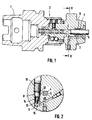
- the one formed by a thin section extends Stretch ceiling 7 of the sleeve 3 over a large axial section and is not like in known hydraulic chucks in the middle by a thick ring section stiffened.
- a piston 8 which in a hydraulic cylinder bore 9 via a Clamping screw 10 is adjustable.
- the hydraulic cylinder bore with oil or another hydraulic fluid is filled, communicates with the annular space 11, the surrounds the stretch ceiling 7.
- the piston is in the embodiment shown from a pressure piece 12 with a molded thinner mandrel 13 on which a Sealing body 14 made of rubber-elastic material, plastic or the like sits.
- the thorn 13 protrudes from the front over the sealing body 14 and can be used as a limit stop serve so that the screw 8 of the piston 8 is not shifted too far can be and then the stretch ceiling is overloaded.
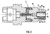
- Fig. 3 is to achieve a safe Sealing the sleeve 3 in the receiving space 15 of the hydraulic expansion chuck 2 an O-ring seal selected.
- the sleeve 3 is on both sides of the Stretch ceiling 7 provided with annular grooves 16 open to the outside, in which O-rings 17 are inserted, which provide a secure seal to the inner wall 18 of the receiving space guarantee.
- the sleeve section is preferably on the right the outer end of the sleeve 3 is non-displaceably held in the receptacle 15, while such an interference fit is missing at the inner end.
- the edge is correspondingly radially reset and there can be no damage when inserting the O-ring 17.
Landscapes
- Engineering & Computer Science (AREA)
- Mechanical Engineering (AREA)
- Gripping On Spindles (AREA)
- Clamps And Clips (AREA)
Abstract
Description
- Fig. 1
- einen Schnitt durch ein erfindungsgemäßes Hydrodehnspannfutter,
- Fig. 2
- einen Querschnitt längs der Linie II-II in Fig. 1, und
- Fig. 3
- einen der Fig. 1 entsprechenden Schnitt durch ein abgewandeltes Hydrodehnspannfutter mit O-Ringabdichtung der Hülse.
Claims (7)
- Hydrodehnspannfutter mit wenigstens einer den Schaft eines zu spannenden Werkzeugs klemmend umfassenden Spanndecke in Form einer elastischen Hülse, die eine Hydraulikkammer begrenzt, deren Volumen durch einen Kolben veränderbar ist, insbesondere für Gewindebohrer, dadurch gekennzeichnet, dass hinter der Hydrodehnspannstelle eine Vierkantmitnahme (4) für das endseitig mit einem Vierkantabschnitt (5) versehene Werkzeug (6) angeordnet ist und dass die Spanndecke (7) weichelastisch mit großem Spannweg ausgebildet ist.
- Hydrodehnspannfutter nach Anspruch 1, dadurch gekennzeichnet, dass die Spanndecke (7) sich durchgehend über die gesamte Spannlänge des Werkzeugs erstreckt.
- Hydrodehnspannfutter nach Anspruch 1 oder 2, dadurch gekennzeichnet, dass der vorzugsweise über eine Spannschraube (10) verstellbare Kolben (3) mit einem Wegbegrenzer versehen ist.
- Hydrodehnspannfutter nach Anspruch 3, dadurch gekennzeichnet, dass der Kolben (8) einen über einen ihn umgebenden Dichtkörper (14) überstehenden Anschlagdorn (13) aufweist, der sich an der Stirnfläche (15) der Hydraulikzylinderbohrung (9) abstützen kann.
- Hydrodehnspannfutter nach einem der Ansprüche 1 bis 4, dadurch gekennzeichnet, dass die Hülse (3) wenigstens an einer Seite, vorzugsweise beidends, neben der Spanndecke durch O-Ringe (17) gegen die Aufnahmewand (18) des Futterkörpers (19) abgedichtet ist.
- Hydrodehnspannfutter nach Anspruch 5, dadurch gekennzeichnet, dass die Hülse (3) ein einends, vorzugsweise am äußeren Ende, mit Presssitz in der Aufnahme (15) des Futterkörpers (19) unverschiebbar gehalten ist.
- Hydrodehnspannfutter nach Anspruch 5 oder 6, dadurch gekennzeichnet, dass die Hülse (3) mit Ringnuten (16) zum Einlegen der O-Ringe (17) versehen ist.
Applications Claiming Priority (2)
| Application Number | Priority Date | Filing Date | Title |
|---|---|---|---|
| DE19947941A DE19947941A1 (de) | 1999-10-06 | 1999-10-06 | Hydrodehnspannfutter |
| DE19947941 | 1999-10-06 |
Publications (2)
| Publication Number | Publication Date |
|---|---|
| EP1090704A1 true EP1090704A1 (de) | 2001-04-11 |
| EP1090704B1 EP1090704B1 (de) | 2004-12-15 |
Family
ID=7924562
Family Applications (1)
| Application Number | Title | Priority Date | Filing Date |
|---|---|---|---|
| EP00106502A Expired - Lifetime EP1090704B1 (de) | 1999-10-06 | 2000-03-25 | Hydrodehnspannfutter |
Country Status (2)
| Country | Link |
|---|---|
| EP (1) | EP1090704B1 (de) |
| DE (2) | DE19947941A1 (de) |
Cited By (6)
| Publication number | Priority date | Publication date | Assignee | Title |
|---|---|---|---|---|
| EP1201341A1 (de) * | 2000-10-16 | 2002-05-02 | Makino Milling Machine Co. Ltd. | Werkzeugmaschinenspindel |
| EP1882537A1 (de) * | 2006-07-25 | 2008-01-30 | Schunk GmbH & Co. KG Spann- und Greiftechnik | Hydraulische Dehnspanneinrichtung |
| EP2174736A1 (de) * | 2008-10-08 | 2010-04-14 | Schunk GmbH & Co. KG Spann- und Greiftechnik | Hydraulische Dehnspanneinrichtung |
| EP2650067A1 (de) | 2012-04-13 | 2013-10-16 | Gühring OHG | Werkzeugaufnahme, insbesondere für ein Gewindeerzeugungswerkzeug |
| WO2014167669A1 (ja) * | 2013-04-10 | 2014-10-16 | 大昭和精機株式会社 | ハイドロチャック |
| CN108587844A (zh) * | 2018-05-18 | 2018-09-28 | 安徽金种子酒业股份有限公司 | 一种白酒酿酒用带压蒸料及蒸汽回收循环装置 |
Families Citing this family (2)
| Publication number | Priority date | Publication date | Assignee | Title |
|---|---|---|---|---|
| DE102010035770B4 (de) | 2010-08-19 | 2012-11-08 | Ewald Schneider | Vorderradgabel für Motorräder |
| DE202011051044U1 (de) | 2011-08-19 | 2012-11-28 | Rainer Pfister | Hydrodehnspannfutter |
Citations (3)
| Publication number | Priority date | Publication date | Assignee | Title |
|---|---|---|---|---|
| US3592482A (en) * | 1968-05-27 | 1971-07-13 | Scully Jones Co | Hydraulic chuck |
| DE3716313A1 (de) * | 1987-05-15 | 1988-11-24 | F X Marquart Gmbh | Ueberlastkupplung fuer einen gewindeschneider |
| DE4317170A1 (de) * | 1993-05-22 | 1994-11-24 | Schunk Fritz Gmbh | Dehnspannwerkzeug zum Spannen und Zentrieren von Werkstücken und/oder Werkzeugen mit Paßdurchmesser und wenigstens einer Plananlage |
-
1999
- 1999-10-06 DE DE19947941A patent/DE19947941A1/de not_active Withdrawn
-
2000
- 2000-03-25 EP EP00106502A patent/EP1090704B1/de not_active Expired - Lifetime
- 2000-03-25 DE DE50008949T patent/DE50008949D1/de not_active Expired - Fee Related
Patent Citations (3)
| Publication number | Priority date | Publication date | Assignee | Title |
|---|---|---|---|---|
| US3592482A (en) * | 1968-05-27 | 1971-07-13 | Scully Jones Co | Hydraulic chuck |
| DE3716313A1 (de) * | 1987-05-15 | 1988-11-24 | F X Marquart Gmbh | Ueberlastkupplung fuer einen gewindeschneider |
| DE4317170A1 (de) * | 1993-05-22 | 1994-11-24 | Schunk Fritz Gmbh | Dehnspannwerkzeug zum Spannen und Zentrieren von Werkstücken und/oder Werkzeugen mit Paßdurchmesser und wenigstens einer Plananlage |
Cited By (12)
| Publication number | Priority date | Publication date | Assignee | Title |
|---|---|---|---|---|
| EP1201341A1 (de) * | 2000-10-16 | 2002-05-02 | Makino Milling Machine Co. Ltd. | Werkzeugmaschinenspindel |
| EP1882537A1 (de) * | 2006-07-25 | 2008-01-30 | Schunk GmbH & Co. KG Spann- und Greiftechnik | Hydraulische Dehnspanneinrichtung |
| EP2174736A1 (de) * | 2008-10-08 | 2010-04-14 | Schunk GmbH & Co. KG Spann- und Greiftechnik | Hydraulische Dehnspanneinrichtung |
| WO2010040427A1 (de) * | 2008-10-08 | 2010-04-15 | Schunk Gmbh & Co. Kg Spann- Und Greiftechnik | Hydraulische dehnspanneinrichtung |
| EP2650067A1 (de) | 2012-04-13 | 2013-10-16 | Gühring OHG | Werkzeugaufnahme, insbesondere für ein Gewindeerzeugungswerkzeug |
| DE102012215039A1 (de) | 2012-04-13 | 2013-10-17 | Gühring Ohg | Werkzeugaufnahme, insbesondere für ein Gewindeerzeugungswerkzeug |
| WO2014167669A1 (ja) * | 2013-04-10 | 2014-10-16 | 大昭和精機株式会社 | ハイドロチャック |
| EP2985099A4 (de) * | 2013-04-10 | 2016-11-30 | Daishowa Seiki | Hydraulisches spannfutter |
| JPWO2014167669A1 (ja) * | 2013-04-10 | 2017-02-16 | 大昭和精機株式会社 | ハイドロチャック |
| US9676040B2 (en) | 2013-04-10 | 2017-06-13 | Daishowa Seiki Kabushiki Kaisha | Hydraulic chuck |
| CN105121078B (zh) * | 2013-04-10 | 2017-11-28 | 大昭和精机株式会社 | 液压卡盘 |
| CN108587844A (zh) * | 2018-05-18 | 2018-09-28 | 安徽金种子酒业股份有限公司 | 一种白酒酿酒用带压蒸料及蒸汽回收循环装置 |
Also Published As
| Publication number | Publication date |
|---|---|
| EP1090704B1 (de) | 2004-12-15 |
| DE50008949D1 (de) | 2005-01-20 |
| DE19947941A1 (de) | 2001-04-12 |
Similar Documents
| Publication | Publication Date | Title |
|---|---|---|
| DE60308014T2 (de) | Dämpfungsvorrichtung zur dämpfung von schwingungen | |
| DE19729249C2 (de) | Spannfutter | |
| DE102010009172B4 (de) | Dehnspanndorn und Dehnspannfutter | |
| EP0171358A2 (de) | Bohrwerkzeug für Handbohrmaschinen | |
| WO2005044491A1 (de) | Dehnspanneinrichtung | |
| WO2005097384A2 (de) | Dehnspanneinrichtung | |
| EP1090704B1 (de) | Hydrodehnspannfutter | |
| EP0768151B1 (de) | Werkzeughalter | |
| DE2501020A1 (de) | Klemmkupplung zum starren verbinden einer antriebsbuchse mit einer darin verschiebbar gefuehrten spindel | |
| DE2614834A1 (de) | Vorrichtung zum zusammenkuppeln von motoren | |
| DE2710236C3 (de) | Schraubenpumpe | |
| CH668723A5 (de) | Revolverkopf fuer eine drehmaschine und hierzu passende werkzeughalter. | |
| DE436453T1 (de) | Werkzeugeinheit mit fuehler. | |
| EP0464335A2 (de) | Schnellwechselfutter mit Längenausgleichsvorrichtung und achszentraler Kühlmittelzuführung | |
| EP0817704B1 (de) | Futter mit kupplung | |
| DE10083312B4 (de) | Dichtungsvorrichtung | |
| DD297089A5 (de) | Werkzeug fuer den einsatz in werkzeugmaschinen | |
| DE3131639A1 (de) | "hydraulisches spaltgeraet" | |
| DE3911159A1 (de) | Kupplung fuer gestaenge mit kraftuebertragung | |
| DE102007041937B4 (de) | Spannfutter | |
| DE2107526C3 (de) | Zahnärztliches Ultraschallgerät | |
| DE102019123665A1 (de) | Pendelhalter-Spannhülse | |
| EP1882537A1 (de) | Hydraulische Dehnspanneinrichtung | |
| DE8910822U1 (de) | Mit der Arbeitsspindel einer handgeführten Elektrowerkzeugmaschine vereinigbarer Adapter | |
| DE4429085C1 (de) | Bohrerschaftverlängerung |
Legal Events
| Date | Code | Title | Description |
|---|---|---|---|
| PUAI | Public reference made under article 153(3) epc to a published international application that has entered the european phase |
Free format text: ORIGINAL CODE: 0009012 |
|
| AK | Designated contracting states |
Kind code of ref document: A1 Designated state(s): DE FR GB IT |
|
| AX | Request for extension of the european patent |
Free format text: AL;LT;LV;MK;RO;SI |
|
| 17P | Request for examination filed |
Effective date: 20010502 |
|
| AKX | Designation fees paid |
Free format text: DE FR GB IT |
|
| GRAP | Despatch of communication of intention to grant a patent |
Free format text: ORIGINAL CODE: EPIDOSNIGR1 |
|
| RAP1 | Party data changed (applicant data changed or rights of an application transferred) |
Owner name: EMUGE-WERK RICHARD GLIMPEL GMBH & CO.KG FABRIK |
|
| GRAS | Grant fee paid |
Free format text: ORIGINAL CODE: EPIDOSNIGR3 |
|
| GRAA | (expected) grant |
Free format text: ORIGINAL CODE: 0009210 |
|
| AK | Designated contracting states |
Kind code of ref document: B1 Designated state(s): DE FR GB IT |
|
| REG | Reference to a national code |
Ref country code: GB Ref legal event code: FG4D Free format text: NOT ENGLISH |
|
| REF | Corresponds to: |
Ref document number: 50008949 Country of ref document: DE Date of ref document: 20050120 Kind code of ref document: P |
|
| PG25 | Lapsed in a contracting state [announced via postgrant information from national office to epo] |
Ref country code: IT Free format text: LAPSE BECAUSE OF NON-PAYMENT OF DUE FEES;WARNING: LAPSES OF ITALIAN PATENTS WITH EFFECTIVE DATE BEFORE 2007 MAY HAVE OCCURRED AT ANY TIME BEFORE 2007. THE CORRECT EFFECTIVE DATE MAY BE DIFFERENT FROM THE ONE RECORDED. Effective date: 20050325 |
|
| GBT | Gb: translation of ep patent filed (gb section 77(6)(a)/1977) |
Effective date: 20050317 |
|
| ET | Fr: translation filed | ||
| PLBE | No opposition filed within time limit |
Free format text: ORIGINAL CODE: 0009261 |
|
| STAA | Information on the status of an ep patent application or granted ep patent |
Free format text: STATUS: NO OPPOSITION FILED WITHIN TIME LIMIT |
|
| 26N | No opposition filed |
Effective date: 20050916 |
|
| PGFP | Annual fee paid to national office [announced via postgrant information from national office to epo] |
Ref country code: FR Payment date: 20060328 Year of fee payment: 7 |
|
| GBPC | Gb: european patent ceased through non-payment of renewal fee |
Effective date: 20070325 |
|
| REG | Reference to a national code |
Ref country code: FR Ref legal event code: ST Effective date: 20071130 |
|
| PG25 | Lapsed in a contracting state [announced via postgrant information from national office to epo] |
Ref country code: GB Free format text: LAPSE BECAUSE OF NON-PAYMENT OF DUE FEES Effective date: 20070325 |
|
| PG25 | Lapsed in a contracting state [announced via postgrant information from national office to epo] |
Ref country code: FR Free format text: LAPSE BECAUSE OF NON-PAYMENT OF DUE FEES Effective date: 20070402 |
|
| PGFP | Annual fee paid to national office [announced via postgrant information from national office to epo] |
Ref country code: DE Payment date: 20080325 Year of fee payment: 9 |
|
| PGFP | Annual fee paid to national office [announced via postgrant information from national office to epo] |
Ref country code: GB Payment date: 20060316 Year of fee payment: 7 |
|
| PGRI | Patent reinstated in contracting state [announced from national office to epo] |
Ref country code: IT Effective date: 20091001 |
|
| PG25 | Lapsed in a contracting state [announced via postgrant information from national office to epo] |
Ref country code: DE Free format text: LAPSE BECAUSE OF NON-PAYMENT OF DUE FEES Effective date: 20091001 |
|
| PGFP | Annual fee paid to national office [announced via postgrant information from national office to epo] |
Ref country code: IT Payment date: 20060331 Year of fee payment: 7 |
|
| PGRI | Patent reinstated in contracting state [announced from national office to epo] |
Ref country code: IT Effective date: 20091001 |