EP1088751A2 - Wheel speed detecting device - Google Patents
Wheel speed detecting device Download PDFInfo
- Publication number
- EP1088751A2 EP1088751A2 EP00121130A EP00121130A EP1088751A2 EP 1088751 A2 EP1088751 A2 EP 1088751A2 EP 00121130 A EP00121130 A EP 00121130A EP 00121130 A EP00121130 A EP 00121130A EP 1088751 A2 EP1088751 A2 EP 1088751A2
- Authority
- EP
- European Patent Office
- Prior art keywords
- pulsar ring
- wheel speed
- detecting device
- pulse
- counting sensor
- Prior art date
- Legal status (The legal status is an assumption and is not a legal conclusion. Google has not performed a legal analysis and makes no representation as to the accuracy of the status listed.)
- Granted
Links
Images


Classifications
-
- B—PERFORMING OPERATIONS; TRANSPORTING
- B60—VEHICLES IN GENERAL
- B60T—VEHICLE BRAKE CONTROL SYSTEMS OR PARTS THEREOF; BRAKE CONTROL SYSTEMS OR PARTS THEREOF, IN GENERAL; ARRANGEMENT OF BRAKING ELEMENTS ON VEHICLES IN GENERAL; PORTABLE DEVICES FOR PREVENTING UNWANTED MOVEMENT OF VEHICLES; VEHICLE MODIFICATIONS TO FACILITATE COOLING OF BRAKES
- B60T1/00—Arrangements of braking elements, i.e. of those parts where braking effect occurs specially for vehicles
- B60T1/02—Arrangements of braking elements, i.e. of those parts where braking effect occurs specially for vehicles acting by retarding wheels
- B60T1/06—Arrangements of braking elements, i.e. of those parts where braking effect occurs specially for vehicles acting by retarding wheels acting otherwise than on tread, e.g. employing rim, drum, disc, or transmission or on double wheels
- B60T1/065—Arrangements of braking elements, i.e. of those parts where braking effect occurs specially for vehicles acting by retarding wheels acting otherwise than on tread, e.g. employing rim, drum, disc, or transmission or on double wheels employing disc
-
- B—PERFORMING OPERATIONS; TRANSPORTING
- B60—VEHICLES IN GENERAL
- B60T—VEHICLE BRAKE CONTROL SYSTEMS OR PARTS THEREOF; BRAKE CONTROL SYSTEMS OR PARTS THEREOF, IN GENERAL; ARRANGEMENT OF BRAKING ELEMENTS ON VEHICLES IN GENERAL; PORTABLE DEVICES FOR PREVENTING UNWANTED MOVEMENT OF VEHICLES; VEHICLE MODIFICATIONS TO FACILITATE COOLING OF BRAKES
- B60T8/00—Arrangements for adjusting wheel-braking force to meet varying vehicular or ground-surface conditions, e.g. limiting or varying distribution of braking force
- B60T8/17—Using electrical or electronic regulation means to control braking
- B60T8/1701—Braking or traction control means specially adapted for particular types of vehicles
- B60T8/1706—Braking or traction control means specially adapted for particular types of vehicles for single-track vehicles, e.g. motorcycles
-
- B—PERFORMING OPERATIONS; TRANSPORTING
- B60—VEHICLES IN GENERAL
- B60T—VEHICLE BRAKE CONTROL SYSTEMS OR PARTS THEREOF; BRAKE CONTROL SYSTEMS OR PARTS THEREOF, IN GENERAL; ARRANGEMENT OF BRAKING ELEMENTS ON VEHICLES IN GENERAL; PORTABLE DEVICES FOR PREVENTING UNWANTED MOVEMENT OF VEHICLES; VEHICLE MODIFICATIONS TO FACILITATE COOLING OF BRAKES
- B60T8/00—Arrangements for adjusting wheel-braking force to meet varying vehicular or ground-surface conditions, e.g. limiting or varying distribution of braking force
- B60T8/17—Using electrical or electronic regulation means to control braking
- B60T8/171—Detecting parameters used in the regulation; Measuring values used in the regulation
-
- B—PERFORMING OPERATIONS; TRANSPORTING
- B60—VEHICLES IN GENERAL
- B60T—VEHICLE BRAKE CONTROL SYSTEMS OR PARTS THEREOF; BRAKE CONTROL SYSTEMS OR PARTS THEREOF, IN GENERAL; ARRANGEMENT OF BRAKING ELEMENTS ON VEHICLES IN GENERAL; PORTABLE DEVICES FOR PREVENTING UNWANTED MOVEMENT OF VEHICLES; VEHICLE MODIFICATIONS TO FACILITATE COOLING OF BRAKES
- B60T8/00—Arrangements for adjusting wheel-braking force to meet varying vehicular or ground-surface conditions, e.g. limiting or varying distribution of braking force
- B60T8/32—Arrangements for adjusting wheel-braking force to meet varying vehicular or ground-surface conditions, e.g. limiting or varying distribution of braking force responsive to a speed condition, e.g. acceleration or deceleration
- B60T8/321—Arrangements for adjusting wheel-braking force to meet varying vehicular or ground-surface conditions, e.g. limiting or varying distribution of braking force responsive to a speed condition, e.g. acceleration or deceleration deceleration
- B60T8/329—Systems characterised by their speed sensor arrangements
-
- B—PERFORMING OPERATIONS; TRANSPORTING
- B62—LAND VEHICLES FOR TRAVELLING OTHERWISE THAN ON RAILS
- B62J—CYCLE SADDLES OR SEATS; AUXILIARY DEVICES OR ACCESSORIES SPECIALLY ADAPTED TO CYCLES AND NOT OTHERWISE PROVIDED FOR, e.g. ARTICLE CARRIERS OR CYCLE PROTECTORS
- B62J45/00—Electrical equipment arrangements specially adapted for use as accessories on cycles, not otherwise provided for
- B62J45/40—Sensor arrangements; Mounting thereof
- B62J45/41—Sensor arrangements; Mounting thereof characterised by the type of sensor
- B62J45/412—Speed sensors
-
- B—PERFORMING OPERATIONS; TRANSPORTING
- B62—LAND VEHICLES FOR TRAVELLING OTHERWISE THAN ON RAILS
- B62J—CYCLE SADDLES OR SEATS; AUXILIARY DEVICES OR ACCESSORIES SPECIALLY ADAPTED TO CYCLES AND NOT OTHERWISE PROVIDED FOR, e.g. ARTICLE CARRIERS OR CYCLE PROTECTORS
- B62J45/00—Electrical equipment arrangements specially adapted for use as accessories on cycles, not otherwise provided for
- B62J45/40—Sensor arrangements; Mounting thereof
- B62J45/42—Sensor arrangements; Mounting thereof characterised by mounting
- B62J45/423—Sensor arrangements; Mounting thereof characterised by mounting on or besides the wheel
-
- B—PERFORMING OPERATIONS; TRANSPORTING
- B62—LAND VEHICLES FOR TRAVELLING OTHERWISE THAN ON RAILS
- B62L—BRAKES SPECIALLY ADAPTED FOR CYCLES
- B62L1/00—Brakes; Arrangements thereof
-
- G—PHYSICS
- G01—MEASURING; TESTING
- G01P—MEASURING LINEAR OR ANGULAR SPEED, ACCELERATION, DECELERATION, OR SHOCK; INDICATING PRESENCE, ABSENCE, OR DIRECTION, OF MOVEMENT
- G01P1/00—Details of instruments
- G01P1/04—Special adaptations of driving means
-
- G—PHYSICS
- G01—MEASURING; TESTING
- G01P—MEASURING LINEAR OR ANGULAR SPEED, ACCELERATION, DECELERATION, OR SHOCK; INDICATING PRESENCE, ABSENCE, OR DIRECTION, OF MOVEMENT
- G01P3/00—Measuring linear or angular speed; Measuring differences of linear or angular speeds
- G01P3/42—Devices characterised by the use of electric or magnetic means
- G01P3/44—Devices characterised by the use of electric or magnetic means for measuring angular speed
- G01P3/48—Devices characterised by the use of electric or magnetic means for measuring angular speed by measuring frequency of generated current or voltage
- G01P3/481—Devices characterised by the use of electric or magnetic means for measuring angular speed by measuring frequency of generated current or voltage of pulse signals
- G01P3/488—Devices characterised by the use of electric or magnetic means for measuring angular speed by measuring frequency of generated current or voltage of pulse signals delivered by variable reluctance detectors
-
- G—PHYSICS
- G01—MEASURING; TESTING
- G01P—MEASURING LINEAR OR ANGULAR SPEED, ACCELERATION, DECELERATION, OR SHOCK; INDICATING PRESENCE, ABSENCE, OR DIRECTION, OF MOVEMENT
- G01P3/00—Measuring linear or angular speed; Measuring differences of linear or angular speeds
- G01P3/42—Devices characterised by the use of electric or magnetic means
- G01P3/50—Devices characterised by the use of electric or magnetic means for measuring linear speed
Definitions
- This invention relates to a wheel speed detecting device which detects the rotational speed of a wheel.
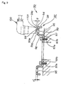
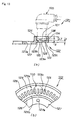
- Fig. 18 is a side view of a prior art wheel speed detecting device.
- the wheel speed detecting device mounted on the rear wheel of a motorcycle will be explained below.
- a sensor ring (hereinafter referred to as the "pulsar ring") 154 is attached on a spoke portion 152 of a rear wheel 151; and a pulse counting sensor 156 (e.g., an electromagnetic rotary sensor) is attached on a swing arm 155 which supports the rear wheel 151, oppositely to teeth 154 of the pulsar ring 153.
- a pulse counting sensor 156 e.g., an electromagnetic rotary sensor
- the pulsar ring 153 also rotates together with the rear wheel 151, while the teeth 154 of the pulsar ring 153 are passing the pulse counting sensor 156.
- the pulse counting sensor 156 counts the teeth 154 that have passed, thus detecting the wheel speed of the rear wheel 151 (the rotational speed of the rear wheel 151).
- the pulse counting sensor 156 To improve the detection accuracy of the teeth 154 by the pulse counting sensor 156, it is desirable to mount the pulse counting sensor 156 close to the teeth 154. To mount the pulse counting sensor 156 close to the teeth 154, it is necessary to set the flatness of the pulsar ring 153 (particularly, the teeth 154 ).
- the teeth 154 of the pulsar ring 153 therefore, have been formed by a cutting process to set the flatness of the pulsar ring 153 (especially the teeth 154 ) within the permissible range.
- the processing of the pulsar ring 153 needs time and labor, becoming a factor for increasing the cost.
- Forming the pulsar ring 153 by pressing is also considered. However, because the teeth 154 are relatively long and slender, the pulsar ring 153, if processed by pressing, the teeth 154 will be subject to warpage.
- the wheel speed detecting device comprises a pulsar ring attached on the wheel side and a pulse counting sensor attached on the vehicle body side.
- the pulsar ring comprises a disc, and pulse detecting holes or pulse detecting recesses provided at a predetermined pitch on a pitch circle drawn in a radially inward circumferential position spaced at a distance from an outer edge of the disc.
- the pulse detecting hole is opened in a position on the center side off from an outer edge of the pulsar ring, whereby the outer edge of the pulsar ring can be left in a circular shape. Therefore, it is possible to restrain the warpage of the pulsar ring by the outer edge if the pulse detecting hole is formed by pressing. The flatness of the pulsar ring, therefore, can be held within the permissible range.
- a stiffening rib is provided in the vicinity of, or on the back side of, the sensing surface.
- the sensing surface can be increased in rigidity by providing the stiffening rib in the vicinity of, or on the back side of, the sensing surface. Therefore, if the pulsar ring is set to a little plate thickness, it is possible to hold the flatness of the sensing surface within the permissible range, thereby enabling reduction of pulsar ring weight.
- a third aspect is characterized in that the stiffening rib is provided along the sensing surface, and the height of this stiffening rib is set larger than the clearance from the sensing surface to the pulse counting sensor.
- the stiffening rib is provided along the sensing surface and the height of this stiffening rib is increased larger than the clearance from the sensing surface to the pulse counting sensor. Therefore, it is possible to cover the clearance between the sensing surface and the pulse counting sensor with the stiffening rib; the stiffening rib being usable as the protective cover. Therefore, the clearance between the sensing surface and the pulse counting sensor is protected by the stiffening rib, so that the clearance can be prevented from biting a flying substance such as a flying rock.
- stiffening rib is usable as a protective cover, no individual protective cover is needed, thereby preventing an increase in component count and furthermore time and effort for installing the protective cover can be dispensed with.
- the stiffening rib is formed by bending the outer edge of the disc.
- the wheel speed detecting device can be improved in quality by increasing the rigidity of the pulsar ring with the outer edge of the disc bent.
- the pulsar ring of predetermined thickness being usable, can be decreased in weight, making it possible to decrease cost and to improve vehicle performance.
- a fifth aspect is characterized in that the pulsar ring is prepared from a pressed part with punched pulse detecting holes; and where one of both sides of the pulsar ring which faces to a punch is called the first side and the other is the second side, the pulsar ring is attached so that the second surface will face the pulse counting sensor.
- the pulsar ring is attached with the second side having sharp-edge holes directed toward the pulse counting sensor.
- the sensing performance of the pulse counting sensor can be improved.
- This invention of the above-described configuration has the following advantages.
- the pulse detecting holes is formed in a radially inward position apart from the outer edge of the pulsar ring, and therefore the outer edge of the pulsar ring can be left in a circular form. Therefore, it is possible to prevent pulsar ring warpage by the outer edge if the pulse detecting hole is made by pressing.
- the flatness of the pulsar ring can be kept within the permissible range, thereby lowering the pulsar ring cost.
- the detecting accuracy of the wheel speed detecting device can be enhanced.
- the rigidity of the sensing surface can be increased by forming the stiffening rib in the vicinity of, or on the back side of, the sensing surface. Consequently, it is possible to keep the flatness of the sensing surface within the permissible range if the plate thickness of the pulsar ring is set small, and accordingly to reduce the weight of the pulsar ring.
- the flatness of the pulsar ring can be kept within the permissible range, the detecting accuracy of the wheel speed detecting device can be improved.
- the stiffening rib is provided along the sensing surface; and the stiffening rib has been increased in height larger than the distance from the sensing surface to the pulse counting sensor. Therefore, the clearance between the sensing surface and the pulse counting sensor can be covered with the stiffening rib, which is usable as a protective cover.
- the clearance between the sensing surface and the pulse counting sensor is protected with the stiffening rib, it is possible to prevent entrance of a flying substance, such as a flying rock, into the clearance, and accordingly to enhance the detecting accuracy of the wheel speed detecting device.
- stiffening rib is usable as a protective cover, no separate protective cover is needed; and therefore it is possible to prevent an increase in the component count, to dispense with protective cover installation, and therefore to lower cost.
- the outer edge of the disc is bent to increase the rigidity of the pulsar ring, thereby improving disc quality and enabling wheel speed detection accuracy.
- the edge portion of the punched hole in the first surface becomes round, while the edge portion of the punched hole in the second surface becomes sharp.
- the pulsar ring is placed with the second surface having the sharp edge facing toward the pulse counting sensor.
- the sensing performance of the pulse counting sensor can be improved. As a result, it is possible to enhance the detecting accuracy of the wheel speed detecting device.
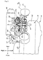
- Fig. 1 is the left side view of a motorcycle of the invention.
- the motorcycle 10 is, a scooter-type vehicle comprising such prime constituents as a vehicle frame 11, a front fork 13 attached to a head pipe 12 of the vehicle frame 11, a front wheel 14 attached on the front fork 13, a handlebar 15 connected to the front fork 13, a swing unit 16 (engine 16a and transmission 16b) attached on the rear upper part of the vehicle frame 11, a rear wheel 17 attached on the rear part of the swing unit 16, a seat 19 mounted on the rear upper part of the vehicle frame 11, and a body cover 20 covering the vehicle frame 11.
- a scooter-type vehicle comprising such prime constituents as a vehicle frame 11, a front fork 13 attached to a head pipe 12 of the vehicle frame 11, a front wheel 14 attached on the front fork 13, a handlebar 15 connected to the front fork 13, a swing unit 16 (engine 16a and transmission 16b) attached on the rear upper part of the vehicle frame 11, a rear wheel 17 attached on the rear part of the swing unit 16, a seat 19 mounted on the rear upper part of the vehicle frame 11, and a body cover 20
- the body cover 20 comprises a front cover 21 covering the front part of the head pipe 12 and the upper part of the front wheel 14, an inner cover 22 covering the rear part of the front cover 21, right and left floor steps 23 (only the left floor step 23 is shown in Fig. 1 and the following) as low-floor type foot rests for the driver, right and left floor skirt 24 extended downward from the outer edge of the floor step 23, an under cover 25 covering the lower edge of the floor skirt 24, a center cover 26 extended to the rear from the inner cover 22 to cover the central part in the longitudinal direction of the vehicle frame 11, and a side cover 27 extended to the rear from the center cover 26 to cover both sides of the rear part of the vehicle frame 11.
- reference numeral 28 denotes a hydraulic front disc brake; 29a, a front fender; 29b, a headlight; 29c, a windshield; 29d, a handle cover; 29e, a handle grip; 29f, a mirror; 29g, a fuel tank; 29h, an engine cooling radiator; 29j, a foldable bar step for a rear seat passenger; 29k, a main stand; 29m, an air cleaner,; 29n, a taillight; 29p, a rear fender; 29q, a storage box; 29s, rear brake operating member; and 29t, a rear suspension.
- Fig. 2 is a plan view of a motorcycle with the wheel speed detecting device (of the first embodiment) according to this invention mounted on the rear wheel.
- the left rear part of the swing unit 16 that is, the left rear part 32 of the transmission case 31, on the left side of the vehicle centerline (CL) (the center of vehicle width) extends to the rear along the vehicle CL. Therefore, the left rear part 32 of the transmission case 31 is extended longer to the rear than the right rear end part 33.
- the swing arm 35 is attached at the front part by a bolt 36 midway in the longitudinal direction of the swing unit 16, that is, at the right rear end part 33 of the transmission case 31; the swing arm 35 is extended to the rear, so that a rear axle 37 is rotatably supported by the left rear part 32 of the transmission case 31 and the rear part of the swing arm 35; and the rear wheel 17 is mounted to the rear axle 37.
- the rear wheel 17 can be supported between the rear part of the swing unit 16 and the rear part of the swing arm 35.
- Reference numeral 46 denotes a muffler; 47, a bolt; and 48, a bracket.
- a rear brake 40 and a wheel speed detecting device 50 (for the rear wheel) of the invention are mounted at the rear part of the motorcycle10 at the rear part of the motorcycle10 at the rear part of the motorcycle10 at the rear part of the motorcycle10 at the rear part of the motorcycle10.
- the rear brake 40 is a hydraulic rear disc brake comprising a disc-like brake disc 41 bolted to the right side of a hub 18 of the rear wheel 17, and a caliper 42 bolted to the swing arm 35 for brake control of the brake disc 41.
- the wheel speed detecting device (for the rear wheel) 50 comprises a pulsar ring 52 bolted to the right side of the wheel side (the hub 18 of the rear wheel 17), and a pulse counting sensor 60 bolted to the vehicle body side (the swing arm 35).
- the wheel speed detecting device (for the rear wheel) 50 of the invention will now be described in detail.
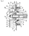
- Fig. 3 is an enlarged view of the section 3 in Fig. 2, that is, a sectional view of the wheel speed detecting device (for the rear wheel) of the invention.
- the wheel speed detecting device (for the rear wheel) 50 functions to count pulse detecting holes 57 made in the pulsar ring 52 by means of the pulse counting sensor 60, and to detect the rotational speed (wheel speed) of the rear wheel 17 (shown in Fig. 2).
- the pulsar ring 52 is comprised of a cylindrical portion 53 which can be fitted in the recess portion 18a of the hub 18, a seat plate 54 formed on the bottom the cylindrical portion 53, a disc 55 formed on the top of the cylindrical portion 53, pulse detecting holes 57 made at predetermined pitches near the center of a predetermined distance from the outer edge 56 of the disc 55 (see Fig. 4 also), and a bent portion (hereinafter referred to as the "bent portion 56") formed by bending the outer edge 56 of the disc 55.
- the pulsar ring 52 has four bolt holes 54a made in the seat plate 54, and is installed to the recess portion 18a of the hub 18 by inserting the bolts 59 into the bolt holes 54a and tightening the bolts 59 into the hub 18.
- the hub 18 is positioned properly in a predetermined position in the direction of vehicle width in order to position the rear wheel in a predetermined position in the direction of the wheel width. Therefore, the pulsar ring 52 can readily be located in a desired position in the direction of the vehicle width by mounting the pulsar ring 52 in the recess portion 18a of the hub 18. The pulsar ring, therefore, can be installed in a short time.
- the pulse counting sensor 60 is an electromagnetic rotary sensor, including a body 62 inserted into a mounting hole 35b of the swing arm 35, and an overhanging plate 63 extended unitarily from the body 62 and pressed against the swing arm 35 by the bolts 65, 65.
- the detecting portion 62a of the pulse counting sensor 60 can be mounted at a predetermined spacing ⁇ correspondingly to the pulse detecting holes 57 of the pulsar ring 52 by attaching the pulse counting sensor 60 to the swing arm 35.
- the predetermined spacing ⁇ can be made smaller by using the electromagnetic rotary sensor as the pulse counting sensor 60, thereby improving the detecting accuracy. Therefore, it is necessary to set the flatness of the pulsar ring 52 within the permissible range.
- Fig. 4 is a sectional view taken along line 4-4 of Fig. 2.
- the swing arm 35 (an approximately triangular plate tapering toward the rear as viewed from side) is attached at the base portion by two upper and lower bolts 38, 38 to the swing unit 16; and at the lower slanting portion is formed a recess portion 35a, which is curved upward. In this recess portion 35a the caliper 41 is mounted.
- the pulse counting sensor 60 is attached by bolts 65, 65.
- the pitch circle PD is drawn near the center of a predetermined distance from the outer edge 56 of the disc 55 of the pulsar ring 52.
- the pulse detecting holes 57 are made at a predetermined pitch P.
- the pulse detecting hole 57 is a slit (a narrow clearance).
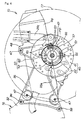
- Fig. 5 is an exploded perspective view of the wheel speed detecting device (for the rear wheel) (the first embodiment) according to this invention.
- the bolts 59 are inserted into the bolt holes 54a of the seat plate 54 of the pulsar ring 52, to thereby attach the pulsar ring 52 to the hub 18.
- the brake disk 41 Outside of the pulsar ring 52 is mounted the brake disk 41.
- the bolts 45 are inserted into the bolt holes 41a of the brake disk 41, to attach the brake disc 41 to the hub 18.
- the body 62 of the pulse counting sensor 60 protrudes out of the hole 35b of the swing arm 35.
- the pulse counting sensor 60 is placed in the vicinity of the side of the pulsar ring 52. It is, therefore, possible to layout the wheel speed detecting device (for the rear wheel) 50 in compact design.
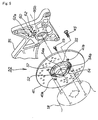
- Figs. 6 (a) and (b) are drawings explaining the method of fabricating the pulsar ring of the wheel speed detecting device (for the rear wheel) of the first embodiment according to this invention.
- a blank is pressed into a shaped body 58 unitarily including the cylindrical portion 53, seat plate 54, disc 54, and bent portion 55.
- the pulsar ring can be enhanced in rigidity by forming the bent portion 56 (see Fig. 4 also) on the outer edge of the disc 55. Therefore, it is possible to decrease the plate thickness of the pulsar ring.
- the shaped body 58 is pressed to form a plurality of pulse detecting holes 57 in the disc 55, and four bolt holes 54a (only two holes are shown) in the seat plate 54, thus completing the fabricating process of the pulsar ring 52.
- the outer edge (i.e., the bent portion) of the pulsar ring 52 can be left in a circular shape. Therefore, the disc 55 of the pulsar ring 52 can be prevented from warping by the outer edge 56 if the pulse detecting holes 57 are made by pressing in the disc 55, thereby enabling to keep the flatness of the disc 55 within the permissible range.
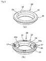
- Figs. 7 are a drawing explaining the pulsar ring of the wheel speed detecting device (for the rear wheel) (the first embodiment) according to this invention.
- (a) to (b) are shown the embodiment of the pulsar ring 52 shaped by pressing, and (c) to (d) show an example for comparison of the prior art pulsar ring 153 (see Fig. 18).
- FIG. 5 shows the pulsar ring 52 with a plurality of pulse detecting holes 57 formed by pressing along the outer edge 56. It is possible to connect the pulse detecting holes 57 at the forward end of the wall portions 57a by the outer edge 57, that is, to form the outer edge of the pulsar ring 52 in a circular shape.
- the distance ⁇ between the pulse counting sensor 60 and the pulsar ring 52 can be set in a desired position.
- (c) shows the pulsar ring 153 with a plurality of teeth 154 formed by pressing along the outer edge thereof. In this state, the plurality of teeth 154 protrude along the outer edge of the pulsar ring 153.
- (d) shows the pulsar ring 153 with the teeth 154 warped at the time of pressing the teeth 154.
- the flatness of the pulsar ring 153 therefore, can not be kept within the permissible range; and accordingly the clearance between the pulse counting sensor 156 and the pulsar ring 153 increases to ( ⁇ +2 ⁇ a ), making it difficult to improve the detecting accuracy.
- the wheel speed detecting device 80 for the front wheel will be explained. It should be noted that the same members as those in the wheel speed detecting device 50 for the rear wheel are designated by the same reference numerals and will not be described.
- Fig. 8 is a side view of the wheel speed detecting device for the front wheel (the second embodiment) according to this invention.
- a front axle 70 is attached by a nut 71 to the front fork 13; the front wheel 14 is rotatably attached to the front fork 13; a brake disc 73 of the hydraulic front disc brake 28 is attached by bolts 74 to the front wheel hub (not shown); a bracket 5 is attached by bolts 76, 76 to the front fork 13; and a brake caliper 77 is attached to the bracket 75, thus being located on the outer peripheral side of the brake disc 73.
- the wheel speed detecting device 80 for the front wheel is comprised of the pulsar ring 52 attached on the front wheel 14 side (an unillustrated front wheel hub), and the pulse counting sensor 60 attached on the vehicle body side (the bracket 75).
- the wheel speed detecting device 80 for the front wheel functions to detect the rotational speed (the wheel speed) of the front wheel 14 by counting the pulse detecting holes 57 in the pulsar ring 52 by means of the pulse counting sensor 60.
- the pulsar ring 52 is located inside of the brake disk 73, and in the vicinity of the side thereof is placed the pulse counting sensor 60. Therefore, it is possible to realize the compact layout of the wheel speed detecting device 80 for the front wheel.
- the pulse counting sensor 60 for the front wheel is an electromagnetic rotary sensor in which the body 62 is inserted into the mounting hole in the bracket 75 and then the overhanging plate 63 is attached by bolts 65, 65 to the bracket 75.
- attaching the pulse counting sensor 60 to the bracket 75 makes it possible to position the detecting portion of the pulse counting sensor 60 for the front wheel oppositely to the pulse detecting holes 57 of the pulsar ring 52.
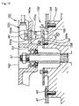
- Fig. 9 is a sectional view of the wheel speed detecting device (the third embodiment) of the invention mounted to the rear wheel.
- a wheel speed detecting device 90 for the rear wheel is comprised of a pulsar ring 92 mounted on the wheel side and a pulse counting sensor 100 mounted on the vehicle body side.
- the pulsar ring 92 includes a disc 93 with a sensing surface 93a directed toward the pulse counting sensor 100, pulse detecting holes 95 formed in the disc at predetermined pitches near the center of a predetermined distance from the outer edge 94 of the disc 93, a stiffening rib (inner rib) 96 formed along the vicinity of the inner periphery 93b of the disc 93, a seat plate 97 formed on the bottom of the inner rib 96, and a stiffening rib (outer rib) formed along the vicinity of the outer region 93c of the disc 93.
- the inner rib 96 is an annular portion formed by bending along the vicinity of the sensing surface 93a, that is, along the vicinity of the inner periphery 93b of the sensing surface 93a.
- the outer rib 98 is an annular portion formed by bending along the vicinity of the sensing surface 93a, that is, along the vicinity of the outer region 93c of the sensing surface 93a.
- the pulsar ring 92 like the pulsar ring 52 of the first embodiment, is provided with four bolt holes 97a (only two holes are shown) in the seat plate 97. Bolts 97b are inserted into these bolt holes 97a and tightened into the hub 99, thereby installing the pulsar ring 92 to the hub 99.
- the hub 99 is properly positioned in a predetermined position in the direction of vehicle width in order to position the rear wheel 17 (shown in Fig. 2) in a predetermined position in the direction of the wheel width. Therefore, it is possible to place the pulsar ring 92 in a desired position in the direction of vehicle width by mounting the pulsar ring 92 on the hub 99.
- the pulse counting sensor 100 like the pulse counting sensor 60 of the first embodiment, is an electromagnetic rotary sensor attached on an unillustrated swing arm, and has a like function as the pulse counting sensor 60.
- the inner and outer ribs 96 and 98 are formed in the vicinity of the sensing surface 93a, that is, along the inner periphery 93b and the outer region 93c of the sensing surface 93a respectively, thereby enabling to improve the rigidity of the disc 93 having the sensing surface 93a.
- the flatness of the sensing surface 93a can be kept within the permissible range even if the plate thickness t of the pulsar ring 92 is set at a small value. It is, therefore, possible to keep a high-accuracy distance ⁇ between the sensing surface 93a and the detecting surface 101 of the pulse counting sensor 100. Therefore, the weight of the pulsar ring 92 can be reduced, thereby decreasing cost and enhancing vehicle performance.
- the detection accuracy of the wheel speed detecting device 90 can be improved.
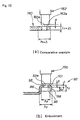
- FIGs. 10 are explanatory views of the rigidity of the wheel speed detecting device (the third embodiment) according to this invention.
- (a) shows a pulsar ring 160 as an example for comparison and
- (b) shows the pulsar ring 92 as an example of the invention, explaining the setting of the plate thickness t of the pulsar ring 92 at one-sixth of the plate thickness t 1 of the pulsar ring 160.
- Equation (3) Equation (3)
- Z 2 h x (10) 2 /6 - (h - 2) x (9) 3 /(6 x 10)
- the modulus of section Z 2 of the pulsar ring 92 can be kept equal to the modulus of section Z 1 of the pulsar ring 160 of (a) if the plate thickness t of the pulsar ring 92 of (b) is reduced to one-sixth of the plate thickness t 1 of the pulsar ring 160 of (a).
- the plate thickness t of the pulsar ring 92 and the length of the inner and outer ribs 96 and 98 may be set to optional values.
- Figs. 11 (a) and (b) are sectional views of the wheel speed detecting device (the fourth embodiment) according to this invention mounted on the rear wheel.
- the wheel speed detecting device 102 for the rear wheel includes a pulsar ring 103 mounted on the wheel side and the pulse counting sensor 100 mounted on the vehicle body side.
- the pulsar ring 103 is comprised of a disc 104 the sensing surface 104a of which is directed toward the pulse counting sensor 100, pulse detecting holes 106 formed at a predetermined pitch near the center of a predetermined distance from the outer edge 105 of the disc 104, a stiffening rib (inner rib) 107 formed along the vicinity of the inner periphery 104b of the disc 104, a seat plate 108 formed at the bottom of the inner rib 107, and a stiffening rib (outer rib) 109 formed along the vicinity of the outer periphery 104c of the disc 104.
- the inner rib 107 is an annular portion formed along the vicinity of the sensing surface 104a, that is, along the vicinity of the inner periphery 104b of the sensing surface 104a.
- the outer rib 109 is an annular portion formed along the vicinity of the sensing surface 104a, that is, along the vicinity of the outer periphery 104c of the sensing surface 104a.
- Reference numeral 108a denotes a bolt hole, which is a hole for bolting the pulsar ring 103 to the hub.
- the inner and outer ribs 107 and 109 are formed in the vicinity of the sensing surface 104a, that is, along the inner periphery 104b and outer periphery 104c of the sensing surface 104a. Therefore, like the third embodiment, the disc 104 constituting the sensing surface 104a can be increased in rigidity.
- the plate thickness t of the pulsar ring 103 is set small, the flatness of the sensing surface 104a can be kept within the permissible range; it is, therefore, possible to accurately keep the distance ⁇ between the sensing surface 104a and the detecting surface 101 of the pulse counting sensor 100. Therefore, it is possible to reduce the weight of the pulsar ring 103.
- the detecting accuracy of the wheel speed detecting device 102 can be enhanced.
- Figs. 12 (a) and (b) are sectional views of the wheel speed detecting device (the fifth embodiment) according to this invention mounted on the rear wheel.
- the wheel speed detecting device 110 for the rear wheel includes a pulsar ring 112mounted on the wheel side and the pulse counting sensor 100 mounted on the vehicle body side.
- the pulsar ring 112 comprises a disc 113 with its sensing surface 113a directed toward the pulse counting sensor 100, pulse detecting recesses 115 formed at a predetermined pitch near the center of a predetermined distance from the outer edge 114 of the disc 113, a stiffening rib 116 formed on the back side 113b (i.e., the back side of the sensing surface 113a) of the disc 113, and a seat plate 117 formed in the inside of the disc 113.
- the stiffening rib 116 is an annular body formed on the back side 113b of the sensing surface 113a.
- Reference numeral 117a denotes a bolt hole, through which the pulsar ring 112 is attached by a bolt to the hub.
- the plate thickness t of the pulsar ring 112 is set small, the flatness of the sensing surface 113a can be held within the permissible range, thus enabling to keep an accurate distance ⁇ between the sensing surface 113a and the detecting surface 101 of the pulse counting sensor 100. It, therefore, is possible to decrease the weight of the pulsar ring 112 and to lower cost.
- the detecting accuracy of the wheel speed detecting device 110 can be enhanced.
- Figs. 13 (a) and (b) are sectional views of the wheel speed detecting device (the sixth embodiment) of the invention mounted on the rear wheel.
- the wheel speed detecting device 120 for the rear wheel comprises a pulsar ring 122 mounted on the wheel side and the pulse counting sensor 100 mounted on the vehicle body side.
- the pulsar ring 122 comprises a disc 123 with its sensing surface 123a directed toward the pulse counting sensor 100, pulse detecting holes 125 opened at a predetermined pitch near the center of a predetermined distance from the outer edge 124 of the disc 123, a stiffening rib (the inner rib) 126 formed along the vicinity of the inner periphery 123b of the disc 123, a seat plate 127 formed on the bottom of the inner rib 126 and inside of the disc 123, and a stiffening rib (the outer rib) 128 formed along the vicinity of the outer periphery 123c of the disc 123.
- the inner rib 126 is an annular body formed along the inner periphery 123b of the sensing surface 123a, with its height L1 being set greater than the distance ⁇ from the sensing surface 123a to the detecting surface 101 of the pulse counting sensor 100.
- the outer rib 128 is an annular body formed along the outer periphery 123c of the sensing surface 123a, with its height L1 being set greater than the distance ⁇ from the sensing surface 123a to the detecting surface 101 of the pulse counting sensor 100.
- the clearance between the sensing surface 123a and the pulse counting sensor 100 i.e., a clearance corresponding to the distance ⁇
- the inner and outer ribs 126 and 128 can be covered with the inner and outer ribs 126 and 128. Therefore, it is possible to keep the clearance between the sensing surface 123a and the pulse counting sensor 100 by the inner and outer ribs 126 and 128, thereby preventing entry of a flying substance such as a flying rock into the clearance.
- Reference numeral 127a denotes a bolt hole, which is used to bolt the pulsar ring 122 to the hub.
- the pulsar ring 122 is provided with inner and outer ribs 126 and 128 formed in the vicinity of the sensing surface 123a, that is, along the inner periphery 123b and outer periphery 123c of the sensing surface 123a, whereby the disc 123 having the sensing surface 123a can be enhanced in rigidity.
- the plate thickness t of the pulsar ring 122 is set small, the flatness of the sensing surface 123a can be held within the permissible range. It is, therefore, possible to accurately keep the distance ⁇ between the sensing surface 123a and the detecting surface 101 of the pulse counting sensor 100, and accordingly to decrease the weight of the pulsar ring 122 and lower the cost.
- the detecting accuracy of the wheel speed detecting device 120 can be improved.
- the inner and outer ribs 126 and 128 are provided along the sensing surface 123a, and the height L1 of the inner and outer ribs 126 and 128 is set greater than the distance ⁇ from the sensing surface 123a to the pulse counting sensor 100. Therefore, the clearance (i.e., the clearance corresponding to the distance ⁇ ) between the sensing surface 123a and the pulse counting sensor 100 can be covered with the inner and outer ribs 126 and 128. That is, the inner and outer ribs 126 and 128 are usable as protective covers.
- the clearance between the sensing surface 123a and the pulse counting sensor 100 is covered by the inner and outer ribs 126 and 128, a flying substance like a flying rock can be prevented from entering the clearance. As a result, the detecting accuracy of the wheel speed detecting device 120 can be further improved.
- the inner and outer ribs 126 and 128 are able to serve also as protective covers, it is unnecessary to provide a separate protective cover, thereby enabling to prevent an increase in the component count, and furthermore to dispense with installation of a protective cover, and consequently to lower the cost.
- the inner and outer ribs 126 and 128 as the stiffening ribs have been explained.
- a similar effect is obtainable also when only either of the inner ribs 126 or outer ribs 128 is provided.
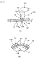
- Fig. 14 is a sectional view of the wheel speed detecting device (the seventh embodiment) of the invention mounted on the rear wheel.
- the pulse detecting holes 135 made in the pulsar ring 132 are counted by means of the pulse counting sensor 100, to thereby detect the rotational speed (the wheel speed) of the rear wheel 17 (shown in Fig. 2).
- the pulsar ring 132 is comprised of a disc 133 mounted by a bolt 138 to the hub 137, and a pulse detecting hole 135 formed at a predetermined pitch on a pitch circle drawn near the center of a predetermined distance from the outer edge 134 of the disc 133.
- the pulsar ring 132 is produced of a pressed part with the pulse detecting hole 135 punched by a punch 139 (shown in Fig.16). Of both sides of the pulsar ring 132, the side directed to the punch 139 is the first surface 132a, and the other side is the second surface 132b. The pulsar ring 132 is attached to the hub 137 in with the second surface 132b directed toward the pulse counting sensor 100.
- the hub 137 is properly positioned in a predetermined position in the direction of vehicle width for the purpose of positioning the rear wheel in the predetermined position in the direction of the wheel width. Therefore, it is possible to mount the pulsar ring 132 in a desired position on the hub 137 in the direction of vehicle width.
- the pulse counting sensor 100 is an electromagnetic rotary sensor of such a configuration that the body 100a is inserted in a mounting hole 140a of a swing arm 140; and the mounting overhanging plate 100b extended unitarily from the body 100a is pressed against the swing arm 140; the overhanging plate 100b being attached by a bolt 141 to the swing arm 140b.
- the detecting surface 101 of the detecting portion 100c is directed toward the second surface 132b of the pulsar ring 132 by attaching the pulse counting sensor 100 to the swing arm 140, and the clearance between the detecting surface 101 and the second surface 132b is set to the predetermined clearance ⁇ .
- Fig. 15 is a sectional view taken along line 15-15 of Fig.14, in which, when the side facing to the punch 139 is called the first surface 132a, and the other side is called the second surface 132b, the pulsar ring 132 is attached with the second surface 132b directed to the pulse counting sensor 100.
- the pulse detecting hole 135 formed by punching with the punch 139 is provided with a sharp square edge 136a on the second surface 132b side (i.e., a part where a hole wall surface 135a of the pulse detecting hole 135 and the sensing surface 133a mutually intersect). Therefore, it is possible to clearly distinguish the sensing surface 133a from the pulse detecting hole 135. Therefore, the sensing performance of the pulse counting sensor 100 can be improved and accordingly the detecting accuracy of the wheel speed detecting device 130 can be enhanced.
- Figs. 16 (a) and (b) are explanatory views of a fabricating process for fabricating the wheel speed detecting device (the seventh embodiment) according to this invention.
- the punch 139 is set on the first surface 132a of the blank 145 and fed down into the first surface 132a.
- the first surface 132a is depressed. At this time, the first surface 132a is slightly depressed at an area within the range H along the outer surface of the punch 139, and there takes place a so-called "droop" 136b along the outer surface of the punch 139.
- the pulsar ring 132 is obtained by punching the pulse detecting hole 135 in the blank 145 by the use of the punch 139.
- the droop 136a occurs along the outer periphery of the pulse detecting hole 135 being made in the first surface 132a.
- Figs. 17 (a) and (b) are explanatory views of operation of the wheel speed detecting device (the seventh embodiment) according to this invention.
- the pulse detecting hole 172 is detected by the pulse counting sensor 175 with the pulsar ring 170 turned in the direction of the arrow. In this case, since the droop 172a of the pulse detecting hole 172 is exposed to the pulse counting sensor 175, the pulse counting sensor 175 detects the depression of the droop 172a.
- the magnetic variation of the pulse counting sensor 100 becomes indefinite, resulting in a failure in accurate detection of the pulse detecting hole 172.
- the pulse detecting hole 135 is detected by the pulse counting sensor 100 with the pulsar ring 132 turned in the direction of the arrow.
- the droop 136b of the pulse detecting hole 135 is positioned on the opposite side of the pulse counting sensor 100, and the detecting hole edge 136a faces to the pulse counting sensor 100.
- the detecting hole edge 136a is formed sharp and square in section, so that the pulse detecting hole 135 is clearly distinguishable from the sensing surface 133a, and accordingly can be accurately detected. Therefore, the magnetic variation of the pulse counting sensor 100 is made clear, enhancing the sensing performance by the pulse counting sensor 100 and accordingly improve the detecting accuracy of the wheel speed detecting device 130.
- the wheel speed detecting device applied to a motorcycle. It should be noticed, however, that the wheel speed detecting device is applicable to other types of motor vehicles.
- the pulse detecting hole 57 of the pulsar ring 52 is a slit and may be a round hole, and furthermore a recess such as a hole may be adopted in place of the pulse detecting hole.
- the adoption of the electromagnetic rotary sensor as the pulse counting sensor 60 is the adoption of the electromagnetic rotary sensor as the pulse counting sensor 60.
- other types of sensors such as a photo sensor, may be used.
- the wheel speed detecting device comprises the pulsar ring mounted on the rear wheel hub , and a pulse counting sensor mounted on the swing arm .
- the pulsar ring comprises the disc , and the pulse detecting holes formed at a predetermined pitch on a pitch circle drawn at a radially inward circumferential position spaced at a predetermined distance from the outer edge of the disc.
- the pulse detecting hole is formed in a position on the center side apart from the outer edge of the pulsar ring, leaving the outer edge of the pulsar ring in a circular form. It is, therefore, possible to prevent warpage of the pulsar ring by the outer edge portion if the pulse detecting holes are made by pressing.
Abstract
Description
- This invention relates to a wheel speed detecting device which detects the rotational speed of a wheel.
- Motorcycles adopting for instance the Antilock Brake System (ABS) are equipped with a wheel speed detecting device for detecting the rotational speed of front and rear wheels. As a prior art wheel speed detecting device, the "Wheel Speed Detecting Device in Motorcycles" disclosed in Japanese Patent Laid-Open No. H8-133154 has been known. This prior art will be explained in detail by referring to Fig. 18.
- Fig. 18 is a side view of a prior art wheel speed detecting device. The wheel speed detecting device mounted on the rear wheel of a motorcycle will be explained below.
- In a wheel speed detecting device 150, a sensor ring (hereinafter referred to as the "pulsar ring") 154 is attached on a spoke portion 152 of a rear wheel 151; and a pulse counting sensor 156 (e.g., an electromagnetic rotary sensor) is attached on a swing arm 155 which supports the rear wheel 151, oppositely to teeth 154 of the pulsar ring 153.
- According to the wheel speed detecting device 150, with the rotation of the rear wheel 151, the pulsar ring 153 also rotates together with the rear wheel 151, while the teeth 154 of the pulsar ring 153 are passing the pulse counting sensor 156. The pulse counting sensor 156 counts the teeth 154 that have passed, thus detecting the wheel speed of the rear wheel 151 (the rotational speed of the rear wheel 151).
- To improve the detection accuracy of the teeth 154 by the pulse counting sensor 156, it is desirable to mount the pulse counting sensor 156 close to the teeth 154. To mount the pulse counting sensor 156 close to the teeth 154, it is necessary to set the flatness of the pulsar ring 153 (particularly, the teeth 154 ).
- In case the flatness of the pulsar ring 153 exceeds the permissible range, unevenness of the pulsar ring 153 increases. It is, therefore, necessary set the pulse counting sensor 156 apart from the teeth 154 with the unevenness taken into account. The detection accuracy of the teeth 154 is hard to improve by the pulse counting sensor 156.
- The teeth 154 of the pulsar ring 153, therefore, have been formed by a cutting process to set the flatness of the pulsar ring 153 (especially the teeth 154 ) within the permissible range. The processing of the pulsar ring 153 needs time and labor, becoming a factor for increasing the cost.
- Forming the pulsar ring 153 by pressing is also considered. However, because the teeth 154 are relatively long and slender, the pulsar ring 153, if processed by pressing, the teeth 154 will be subject to warpage.
- Therefore, it is necessary to correct the warpage of the teeth 154 after pressing the pulsar ring 153, which, however, makes much time and labor, resulting in a factor for increasing cost.
- It, therefore, has been desired to put into practice the wheel speed detecting device capable of enhancing the detecting accuracy and lower cost.
- It is therefore an object of the invention to provide an art which can enhance the detecting accuracy of the wheel speed detecting device and lower the cost.
- In view of the above-described problems, the wheel speed detecting device according to a first aspect of the invention comprises a pulsar ring attached on the wheel side and a pulse counting sensor attached on the vehicle body side. The pulsar ring comprises a disc, and pulse detecting holes or pulse detecting recesses provided at a predetermined pitch on a pitch circle drawn in a radially inward circumferential position spaced at a distance from an outer edge of the disc.
- The pulse detecting hole is opened in a position on the center side off from an outer edge of the pulsar ring, whereby the outer edge of the pulsar ring can be left in a circular shape. Therefore, it is possible to restrain the warpage of the pulsar ring by the outer edge if the pulse detecting hole is formed by pressing. The flatness of the pulsar ring, therefore, can be held within the permissible range.
- According to a second aspect of the invention, when the disc has a sensing surface on the side directed toward the pulse counting sensor, a stiffening rib is provided in the vicinity of, or on the back side of, the sensing surface.
- The sensing surface can be increased in rigidity by providing the stiffening rib in the vicinity of, or on the back side of, the sensing surface. Therefore, if the pulsar ring is set to a little plate thickness, it is possible to hold the flatness of the sensing surface within the permissible range, thereby enabling reduction of pulsar ring weight.
- A third aspect is characterized in that the stiffening rib is provided along the sensing surface, and the height of this stiffening rib is set larger than the clearance from the sensing surface to the pulse counting sensor.
- The stiffening rib is provided along the sensing surface and the height of this stiffening rib is increased larger than the clearance from the sensing surface to the pulse counting sensor. Therefore, it is possible to cover the clearance between the sensing surface and the pulse counting sensor with the stiffening rib; the stiffening rib being usable as the protective cover. Therefore, the clearance between the sensing surface and the pulse counting sensor is protected by the stiffening rib, so that the clearance can be prevented from biting a flying substance such as a flying rock.
- Furthermore, since the stiffening rib is usable as a protective cover, no individual protective cover is needed, thereby preventing an increase in component count and furthermore time and effort for installing the protective cover can be dispensed with.
- In a fourth aspect, the stiffening rib is formed by bending the outer edge of the disc.
- The wheel speed detecting device can be improved in quality by increasing the rigidity of the pulsar ring with the outer edge of the disc bent.
- Furthermore, the pulsar ring of predetermined thickness, being usable, can be decreased in weight, making it possible to decrease cost and to improve vehicle performance.
- A fifth aspect is characterized in that the pulsar ring is prepared from a pressed part with punched pulse detecting holes; and where one of both sides of the pulsar ring which faces to a punch is called the first side and the other is the second side, the pulsar ring is attached so that the second surface will face the pulse counting sensor.
- When the pulse detecting hole is punched from the first side though to the second side, the edge of the hole in the first side becomes round, while the hole in the second side has a sharp edge.
- In the fifth aspect, therefore, the pulsar ring is attached with the second side having sharp-edge holes directed toward the pulse counting sensor.
- By using the pulsar ring having the sharp-edge holes, the sensing performance of the pulse counting sensor can be improved.
- This invention of the above-described configuration has the following advantages.
- According to the first aspect, the pulse detecting holes is formed in a radially inward position apart from the outer edge of the pulsar ring, and therefore the outer edge of the pulsar ring can be left in a circular form. Therefore, it is possible to prevent pulsar ring warpage by the outer edge if the pulse detecting hole is made by pressing.
- Consequently, the flatness of the pulsar ring can be kept within the permissible range, thereby lowering the pulsar ring cost.
- Furthermore the flatness of the pulsar ring that can be kept within the permissible range, the detecting accuracy of the wheel speed detecting device can be enhanced.
- According to the second aspect, the rigidity of the sensing surface can be increased by forming the stiffening rib in the vicinity of, or on the back side of, the sensing surface. Consequently, it is possible to keep the flatness of the sensing surface within the permissible range if the plate thickness of the pulsar ring is set small, and accordingly to reduce the weight of the pulsar ring.
- Furthermore, because the flatness of the pulsar ring can be kept within the permissible range, the detecting accuracy of the wheel speed detecting device can be improved.
- According to the third aspect, the stiffening rib is provided along the sensing surface; and the stiffening rib has been increased in height larger than the distance from the sensing surface to the pulse counting sensor. Therefore, the clearance between the sensing surface and the pulse counting sensor can be covered with the stiffening rib, which is usable as a protective cover.
- Therefore, since the clearance between the sensing surface and the pulse counting sensor is protected with the stiffening rib, it is possible to prevent entrance of a flying substance, such as a flying rock, into the clearance, and accordingly to enhance the detecting accuracy of the wheel speed detecting device.
- Furthermore, because the stiffening rib is usable as a protective cover, no separate protective cover is needed; and therefore it is possible to prevent an increase in the component count, to dispense with protective cover installation, and therefore to lower cost.
- According to the fourth aspect, the outer edge of the disc is bent to increase the rigidity of the pulsar ring, thereby improving disc quality and enabling wheel speed detection accuracy.
- Furthermore, it is possible to prevent an increase in the plate thickness of the pulsar ring by increasing the rigidity of the pulsar ring. Consequently, cost reduction and enhanced vehicle performance are realized by reducing the weight of the pulsar ring.
- According to the fifth aspect, when the pulsar ring is punched through from the first surface to the second surface, the edge portion of the punched hole in the first surface becomes round, while the edge portion of the punched hole in the second surface becomes sharp.
- In the fifth aspect, therefore, the pulsar ring is placed with the second surface having the sharp edge facing toward the pulse counting sensor.
- In the case of the pulsar ring having the sharp, square edge hole, the sensing performance of the pulse counting sensor can be improved. As a result, it is possible to enhance the detecting accuracy of the wheel speed detecting device.
- Preferred embodiments of the invention will be explained with reference to the accompanying drawings. In the drawings, the "front", "rear", "left", "right", "upper" and "lower" designations refer to the orientation of the motorcycle in relation to the driver when sitting normally in the driver's seat. The drawings are to be viewed in the direction of reference numerals.
-
- Fig. 1 is a left side view of a motorcycle of the invention;
- Fig. 2 is a plan view of a motorcycle with a wheel speed detecting device (the first embodiment) of the invention mounted to the rear wheel;
- Fig. 3 is an enlarged view of the section 3 in Fig. 2;
- Fig. 4 is a sectional view taken along line 4-4 of Fig. 2;
- Fig. 5 is an exploded perspective view of the wheel speed detecting device (the first embodiment) for the rear wheel of the invention;
- Fig. 6 is a view explaining the method of fabricating a pulsar ring of the wheel speed detecting device (the first embodiment) for the rear wheel of the invention;
- Fig. 7 is a view explaining the pulsar ring of the wheel speed detecting device (the first embodiment) for the rear wheel of the invention;
- Fig. 8 is a side view of the wheel speed detecting device (the second embodiment) for the front wheel of the invention;
- Fig. 9 is a sectional view of the wheel speed detecting device (the third embodiment) of the invention mounted on the rear wheel;
- Fig. 10 is an explanatory view of rigidity of the wheel speed detecting device (the third embodiment) of the invention;
- Fig. 11 is a sectional view of the wheel speed detecting device (the fourth embodiment) of the invention mounted on the rear wheel;
- Fig. 12 is a sectional view of the wheel speed detecting device (the fifth embodiment) of the invention mounted on the rear wheel;
- Fig. 13 is a sectional view of the wheel speed detecting device (the sixth embodiment) of the invention mounted on the rear wheel;
- Fig. 14 a sectional view of the wheel speed detecting device (the seventh embodiment) of the invention mounted on the rear wheel;
- Fig. 15 is a sectional view taken along line 15-15 of Fig. 14;
- Fig. 16 is an explanatory view of a fabricating process of the wheel speed detecting device (the seventh embodiment) of the invention;
- Fig. 17 is an explanatory view of operation of the wheel speed detecting device (the seventh embodiment) of the invention;
- Fig. 18 is a side view of a conventional wheel speed detecting device.
-
- Fig. 1 is the left side view of a motorcycle of the invention.
- The motorcycle 10 is, a scooter-type vehicle comprising such prime constituents as a vehicle frame 11, a front fork 13 attached to a head pipe 12 of the vehicle frame 11, a front wheel 14 attached on the front fork 13, a handlebar 15 connected to the front fork 13, a swing unit 16 (engine 16a and transmission 16b) attached on the rear upper part of the vehicle frame 11, a rear wheel 17 attached on the rear part of the swing unit 16, a seat 19 mounted on the rear upper part of the vehicle frame 11, and a body cover 20 covering the vehicle frame 11.
- The body cover 20 comprises a front cover 21 covering the front part of the head pipe 12 and the upper part of the front wheel 14, an inner cover 22 covering the rear part of the front cover 21, right and left floor steps 23 (only the left floor step 23 is shown in Fig. 1 and the following) as low-floor type foot rests for the driver, right and left floor skirt 24 extended downward from the outer edge of the floor step 23, an under cover 25 covering the lower edge of the floor skirt 24, a center cover 26 extended to the rear from the inner cover 22 to cover the central part in the longitudinal direction of the vehicle frame 11, and a side cover 27 extended to the rear from the center cover 26 to cover both sides of the rear part of the vehicle frame 11.
- In the drawing, reference numeral 28 denotes a hydraulic front disc brake; 29a, a front fender; 29b, a headlight; 29c, a windshield; 29d, a handle cover; 29e, a handle grip; 29f, a mirror; 29g, a fuel tank; 29h, an engine cooling radiator; 29j, a foldable bar step for a rear seat passenger; 29k, a main stand; 29m, an air cleaner,; 29n, a taillight; 29p, a rear fender; 29q, a storage box; 29s, rear brake operating member; and 29t, a rear suspension.
- Fig. 2 is a plan view of a motorcycle with the wheel speed detecting device (of the first embodiment) according to this invention mounted on the rear wheel.
- The left rear part of the swing unit 16, that is, the left rear part 32 of the transmission case 31, on the left side of the vehicle centerline (CL) (the center of vehicle width) extends to the rear along the vehicle CL. Therefore, the left rear part 32 of the transmission case 31 is extended longer to the rear than the right rear end part 33.
- In this drawing, the swing arm 35 is attached at the front part by a bolt 36 midway in the longitudinal direction of the swing unit 16, that is, at the right rear end part 33 of the transmission case 31; the swing arm 35 is extended to the rear, so that a rear axle 37 is rotatably supported by the left rear part 32 of the transmission case 31 and the rear part of the swing arm 35; and the rear wheel 17 is mounted to the rear axle 37. As a result, the rear wheel 17 can be supported between the rear part of the swing unit 16 and the rear part of the swing arm 35.
- Reference numeral 46 denotes a muffler; 47, a bolt; and 48, a bracket.
- At the rear part of the motorcycle10 are mounted a rear brake 40 and a wheel speed detecting device 50 (for the rear wheel) of the invention.
- The rear brake 40 is a hydraulic rear disc brake comprising a disc-like brake disc 41 bolted to the right side of a hub 18 of the rear wheel 17, and a caliper 42 bolted to the swing arm 35 for brake control of the brake disc 41.
- The wheel speed detecting device (for the rear wheel) 50 comprises a pulsar ring 52 bolted to the right side of the wheel side (the hub 18 of the rear wheel 17), and a pulse counting sensor 60 bolted to the vehicle body side (the swing arm 35).
- The wheel speed detecting device (for the rear wheel) 50 of the invention will now be described in detail.
- Fig. 3 is an enlarged view of the section 3 in Fig. 2, that is, a sectional view of the wheel speed detecting device (for the rear wheel) of the invention.
- The wheel speed detecting device (for the rear wheel) 50 functions to count pulse detecting holes 57 made in the pulsar ring 52 by means of the pulse counting sensor 60, and to detect the rotational speed (wheel speed) of the rear wheel 17 (shown in Fig. 2).
- The pulsar ring 52 is comprised of a cylindrical portion 53 which can be fitted in the recess portion 18a of the hub 18, a seat plate 54 formed on the bottom the cylindrical portion 53, a disc 55 formed on the top of the cylindrical portion 53, pulse detecting holes 57 made at predetermined pitches near the center of a predetermined distance from the outer edge 56 of the disc 55 (see Fig. 4 also), and a bent portion (hereinafter referred to as the "bent portion 56") formed by bending the outer edge 56 of the disc 55.
- The pulsar ring 52 has four bolt holes 54a made in the seat plate 54, and is installed to the recess portion 18a of the hub 18 by inserting the bolts 59 into the bolt holes 54a and tightening the bolts 59 into the hub 18.
- The hub 18 is positioned properly in a predetermined position in the direction of vehicle width in order to position the rear wheel in a predetermined position in the direction of the wheel width. Therefore, the pulsar ring 52 can readily be located in a desired position in the direction of the vehicle width by mounting the pulsar ring 52 in the recess portion 18a of the hub 18. The pulsar ring, therefore, can be installed in a short time.
- The pulse counting sensor 60 is an electromagnetic rotary sensor, including a body 62 inserted into a mounting hole 35b of the swing arm 35, and an overhanging plate 63 extended unitarily from the body 62 and pressed against the swing arm 35 by the bolts 65, 65.
- The detecting portion 62a of the pulse counting sensor 60 can be mounted at a predetermined spacing δ correspondingly to the pulse detecting holes 57 of the pulsar ring 52 by attaching the pulse counting sensor 60 to the swing arm 35.
- The predetermined spacing δ can be made smaller by using the electromagnetic rotary sensor as the pulse counting sensor 60, thereby improving the detecting accuracy. Therefore, it is necessary to set the flatness of the pulsar ring 52 within the permissible range.
- The flatness of the pulsar ring 52 will be explained in detail by referring to Fig. 7.
- Fig. 4 is a sectional view taken along line 4-4 of Fig. 2. In this drawing, the swing arm 35 (an approximately triangular plate tapering toward the rear as viewed from side) is attached at the base portion by two upper and lower bolts 38, 38 to the swing unit 16; and at the lower slanting portion is formed a recess portion 35a, which is curved upward. In this recess portion 35a the caliper 41 is mounted. At the rear end the pulse counting sensor 60 is attached by bolts 65, 65.
- Furthermore, the pitch circle PD is drawn near the center of a predetermined distance from the outer edge 56 of the disc 55 of the pulsar ring 52. On the pitch circle PD the pulse detecting holes 57 are made at a predetermined pitch P. The pulse detecting hole 57 is a slit (a narrow clearance).
- Fig. 5 is an exploded perspective view of the wheel speed detecting device (for the rear wheel) (the first embodiment) according to this invention. In this drawing, the bolts 59 are inserted into the bolt holes 54a of the seat plate 54 of the pulsar ring 52, to thereby attach the pulsar ring 52 to the hub 18. Outside of the pulsar ring 52 is mounted the brake disk 41. Then the bolts 45 are inserted into the bolt holes 41a of the brake disk 41, to attach the brake disc 41 to the hub 18. In this state, the body 62 of the pulse counting sensor 60 protrudes out of the hole 35b of the swing arm 35.
- Inside of the brake disc 41 is mounted the pulsar ring 52. The pulse counting sensor 60 is placed in the vicinity of the side of the pulsar ring 52. It is, therefore, possible to layout the wheel speed detecting device (for the rear wheel) 50 in compact design.
- Next, the method of fabricating the pulsar ring of the wheel speed detecting device (for the rear wheel) described above will be explained.
- Figs. 6 (a) and (b) are drawings explaining the method of fabricating the pulsar ring of the wheel speed detecting device (for the rear wheel) of the first embodiment according to this invention.
- In (a), a blank is pressed into a shaped body 58 unitarily including the cylindrical portion 53, seat plate 54, disc 54, and bent portion 55.
- The pulsar ring can be enhanced in rigidity by forming the bent portion 56 (see Fig. 4 also) on the outer edge of the disc 55. Therefore, it is possible to decrease the plate thickness of the pulsar ring.
- In (b), the shaped body 58 is pressed to form a plurality of pulse detecting holes 57 in the disc 55, and four bolt holes 54a (only two holes are shown) in the seat plate 54, thus completing the fabricating process of the pulsar ring 52.
- Since the portion to be detected of the pulsar ring 52 has been changed from a conventional tooth to the pulse detecting holes 57, the outer edge (i.e., the bent portion) of the pulsar ring 52 can be left in a circular shape. Therefore, the disc 55 of the pulsar ring 52 can be prevented from warping by the outer edge 56 if the pulse detecting holes 57 are made by pressing in the disc 55, thereby enabling to keep the flatness of the disc 55 within the permissible range.
- Figs. 7 (a) and (b) are a drawing explaining the pulsar ring of the wheel speed detecting device (for the rear wheel) (the first embodiment) according to this invention. (a) to (b) are shown the embodiment of the pulsar ring 52 shaped by pressing, and (c) to (d) show an example for comparison of the prior art pulsar ring 153 (see Fig. 18).
- (b) is a view seen from the arrow b in (a), and (d) is a view seen from the arrow d in (c).
- (a) shows the pulsar ring 52 with a plurality of pulse detecting holes 57 formed by pressing along the outer edge 56. It is possible to connect the pulse detecting holes 57 at the forward end of the wall portions 57a by the outer edge 57, that is, to form the outer edge of the pulsar ring 52 in a circular shape.
- (b) shows the outer edge of the pulsar ring 52 having no warpage even after pressing the pulse detecting holes 57. Therefore, it is possible to keep the flatness of the pulsar ring 52 within the permissible range.
- The distance δ between the pulse counting sensor 60 and the pulsar ring 52 can be set in a desired position.
- (c) shows the pulsar ring 153 with a plurality of teeth 154 formed by pressing along the outer edge thereof. In this state, the plurality of teeth 154 protrude along the outer edge of the pulsar ring 153.
- (d) shows the pulsar ring 153 with the teeth 154 warped at the time of pressing the teeth 154. The flatness of the pulsar ring 153, therefore, can not be kept within the permissible range; and accordingly the clearance between the pulse counting sensor 156 and the pulsar ring 153 increases to (
- It is, therefore, necessary set the flatness of the pulsar ring 153 within the permissible range by correcting the warpage a of the teeth 154 after pressing the pulsar ring 153.
- Next, the wheel speed detecting device 80 for the front wheel will be explained. It should be noted that the same members as those in the wheel speed detecting device 50 for the rear wheel are designated by the same reference numerals and will not be described.
- Fig. 8 is a side view of the wheel speed detecting device for the front wheel (the second embodiment) according to this invention. In this drawing, a front axle 70 is attached by a nut 71 to the front fork 13; the front wheel 14 is rotatably attached to the front fork 13; a brake disc 73 of the hydraulic front disc brake 28 is attached by bolts 74 to the front wheel hub (not shown); a bracket 5 is attached by bolts 76, 76 to the front fork 13; and a brake caliper 77 is attached to the bracket 75, thus being located on the outer peripheral side of the brake disc 73.
- The wheel speed detecting device 80 for the front wheel, like the wheel speed detecting device 50 for the rear wheel, is comprised of the pulsar ring 52 attached on the front wheel 14 side (an unillustrated front wheel hub), and the pulse counting sensor 60 attached on the vehicle body side (the bracket 75).
- The wheel speed detecting device 80 for the front wheel functions to detect the rotational speed (the wheel speed) of the front wheel 14 by counting the pulse detecting holes 57 in the pulsar ring 52 by means of the pulse counting sensor 60.
- The pulsar ring 52 is located inside of the brake disk 73, and in the vicinity of the side thereof is placed the pulse counting sensor 60. Therefore, it is possible to realize the compact layout of the wheel speed detecting device 80 for the front wheel.
- The pulse counting sensor 60 for the front wheel, like the pulse counting sensor 60 for the rear wheel, is an electromagnetic rotary sensor in which the body 62 is inserted into the mounting hole in the bracket 75 and then the overhanging plate 63 is attached by bolts 65, 65 to the bracket 75.
- Also like in the wheel speed detecting device 50 for the rear wheel, attaching the pulse counting sensor 60 to the bracket 75 makes it possible to position the detecting portion of the pulse counting sensor 60 for the front wheel oppositely to the pulse detecting holes 57 of the pulsar ring 52.
- Next, the third to seventh embodiments will be explained. The same members as those in the first embodiment are designated by the same reference numerals and will not be described.
- Fig. 9 is a sectional view of the wheel speed detecting device (the third embodiment) of the invention mounted to the rear wheel.
- A wheel speed detecting device 90 for the rear wheel is comprised of a pulsar ring 92 mounted on the wheel side and a pulse counting sensor 100 mounted on the vehicle body side.
- The pulsar ring 92 includes a disc 93 with a sensing surface 93a directed toward the pulse counting sensor 100, pulse detecting holes 95 formed in the disc at predetermined pitches near the center of a predetermined distance from the outer edge 94 of the disc 93, a stiffening rib (inner rib) 96 formed along the vicinity of the inner periphery 93b of the disc 93, a seat plate 97 formed on the bottom of the inner rib 96, and a stiffening rib (outer rib) formed along the vicinity of the outer region 93c of the disc 93.
- The inner rib 96 is an annular portion formed by bending along the vicinity of the sensing surface 93a, that is, along the vicinity of the inner periphery 93b of the sensing surface 93a. The outer rib 98 is an annular portion formed by bending along the vicinity of the sensing surface 93a, that is, along the vicinity of the outer region 93c of the sensing surface 93a.
- The pulsar ring 92, like the pulsar ring 52 of the first embodiment, is provided with four bolt holes 97a (only two holes are shown) in the seat plate 97. Bolts 97b are inserted into these bolt holes 97a and tightened into the hub 99, thereby installing the pulsar ring 92 to the hub 99.
- The hub 99 is properly positioned in a predetermined position in the direction of vehicle width in order to position the rear wheel 17 (shown in Fig. 2) in a predetermined position in the direction of the wheel width. Therefore, it is possible to place the pulsar ring 92 in a desired position in the direction of vehicle width by mounting the pulsar ring 92 on the hub 99.
- The pulse counting sensor 100, like the pulse counting sensor 60 of the first embodiment, is an electromagnetic rotary sensor attached on an unillustrated swing arm, and has a like function as the pulse counting sensor 60.
- According to the pulsar ring 92, the inner and outer ribs 96 and 98 are formed in the vicinity of the sensing surface 93a, that is, along the inner periphery 93b and the outer region 93c of the sensing surface 93a respectively, thereby enabling to improve the rigidity of the disc 93 having the sensing surface 93a.
- Therefore, the flatness of the sensing surface 93a can be kept within the permissible range even if the plate thickness t of the pulsar ring 92 is set at a small value. It is, therefore, possible to keep a high-accuracy distance δ between the sensing surface 93a and the detecting surface 101 of the pulse counting sensor 100. Therefore, the weight of the pulsar ring 92 can be reduced, thereby decreasing cost and enhancing vehicle performance.
- Furthermore, since the flatness of the pulsar ring 92 is kept within the permissible range, the detection accuracy of the wheel speed detecting device 90 can be improved.
- Figs. 10 (a) and (b) are explanatory views of the rigidity of the wheel speed detecting device (the third embodiment) according to this invention. (a) shows a pulsar ring 160 as an example for comparison and (b) shows the pulsar ring 92 as an example of the invention, explaining the setting of the plate thickness t of the pulsar ring 92 at one-sixth of the plate thickness t1 of the pulsar ring 160.
- In (a), setting a great plate thickness t1 of the pulsar ring 160 increases the rigidity of the pulsar ring 160 and also improves the accuracy of the predetermined clearance δ from the detecting surface 162 of the pulse counting sensor 162a to the sensing surface 160a of the pulsar ring 160.
- Assuming that the plate thickness of the pulsar ring 160 is t1 and the width of the sensing surface 160a is h1, the modulus of section Z1 is given by
- Here, presume t1 = 6 mm and
- In (b), suppose that t is the plate thickness of the pulsar ring 92, h2 is the width of the sensing surface 93a, t2 is a distance from the sensing surface 93a to the end of the outer rib 98 (the length of the outer rib 98), t3 is a distance from the inner surface of the disc 93 to the end of the outer rib 98, and h3 is a distance from the inside surface of the inner rib 96 to the inside surface of the outer rib 98, the modulus of section Z2 is given by the following equation.
- It is understood from the above explanation that since the inner and outer ribs 96 and 98 are provided, the modulus of section Z2 of the pulsar ring 92 can be kept equal to the modulus of section Z1 of the pulsar ring 160 of (a) if the plate thickness t of the pulsar ring 92 of (b) is reduced to one-sixth of the plate thickness t1 of the pulsar ring 160 of (a).
- Therefore the pulsar ring 92 of (b), like the pulsar ring 160 of (a), also can be set accurately at the predetermined distance δ from the detecting surface 101 of the pulse counting sensor 100 to the sensing surface 93a.
- The plate thickness t of the pulsar ring 92 and the length of the inner and outer ribs 96 and 98 may be set to optional values.
- It is to be noticed that, in the third embodiment, an example provided with the inner and outer ribs 96 and 98 adopted as stiffening ribs has been explained, and the same effect is obtained if either one of the inner and outer ribs 96 and 98 is adopted.
- Figs. 11 (a) and (b) are sectional views of the wheel speed detecting device (the fourth embodiment) according to this invention mounted on the rear wheel.
- The wheel speed detecting device 102 for the rear wheel includes a pulsar ring 103 mounted on the wheel side and the pulse counting sensor 100 mounted on the vehicle body side.
- The pulsar ring 103 is comprised of a disc 104 the sensing surface 104a of which is directed toward the pulse counting sensor 100, pulse detecting holes 106 formed at a predetermined pitch near the center of a predetermined distance from the outer edge 105 of the disc 104, a stiffening rib (inner rib) 107 formed along the vicinity of the inner periphery 104b of the disc 104, a seat plate 108 formed at the bottom of the inner rib 107, and a stiffening rib (outer rib) 109 formed along the vicinity of the outer periphery 104c of the disc 104.
- The inner rib 107 is an annular portion formed along the vicinity of the sensing surface 104a, that is, along the vicinity of the inner periphery 104b of the sensing surface 104a. The outer rib 109 is an annular portion formed along the vicinity of the sensing surface 104a, that is, along the vicinity of the outer periphery 104c of the sensing surface 104a.
- Reference numeral 108a denotes a bolt hole, which is a hole for bolting the pulsar ring 103 to the hub.
- In the pulsar ring 103, the inner and outer ribs 107 and 109 are formed in the vicinity of the sensing surface 104a, that is, along the inner periphery 104b and outer periphery 104c of the sensing surface 104a. Therefore, like the third embodiment, the disc 104 constituting the sensing surface 104a can be increased in rigidity.
- Therefore, if the plate thickness t of the pulsar ring 103 is set small, the flatness of the sensing surface 104a can be kept within the permissible range; it is, therefore, possible to accurately keep the distance δ between the sensing surface 104a and the detecting surface 101 of the pulse counting sensor 100. Therefore, it is possible to reduce the weight of the pulsar ring 103.
- Furthermore, since the flatness of the pulsar ring 103 can be kept within the permissible range, the detecting accuracy of the wheel speed detecting device 102 can be enhanced.
- In the fourth embodiment, the provision of the inner and outer ribs 96 and 98 as the stiffening ribs has been explained. It should be noticed that the same effect can be obtained even when either one of the inner and outer ribs 96 and 98 is formed.
- Figs. 12 (a) and (b) are sectional views of the wheel speed detecting device (the fifth embodiment) according to this invention mounted on the rear wheel.
- The wheel speed detecting device 110 for the rear wheel includes a pulsar ring 112mounted on the wheel side and the pulse counting sensor 100 mounted on the vehicle body side.
- The pulsar ring 112 comprises a disc 113 with its sensing surface 113a directed toward the pulse counting sensor 100, pulse detecting recesses 115 formed at a predetermined pitch near the center of a predetermined distance from the outer edge 114 of the disc 113, a stiffening rib 116 formed on the back side 113b (i.e., the back side of the sensing surface 113a) of the disc 113, and a seat plate 117 formed in the inside of the disc 113.
- The stiffening rib 116 is an annular body formed on the back side 113b of the sensing surface 113a.
- Reference numeral 117a denotes a bolt hole, through which the pulsar ring 112 is attached by a bolt to the hub.
- In the pulsar ring 112, since the stiffening rib 116 is formed on the back side 113b of the sensing surface 113a, it is possible to increase the rigidity of the disc 113 which constitutes the sensing surface 113a.
- Therefore, if the plate thickness t of the pulsar ring 112 is set small, the flatness of the sensing surface 113a can be held within the permissible range, thus enabling to keep an accurate distance δ between the sensing surface 113a and the detecting surface 101 of the pulse counting sensor 100. It, therefore, is possible to decrease the weight of the pulsar ring 112 and to lower cost.
- Furthermore, as the flatness of the pulsar ring 112 can be held within the permissible range, the detecting accuracy of the wheel speed detecting device 110 can be enhanced.
- Figs. 13 (a) and (b) are sectional views of the wheel speed detecting device (the sixth embodiment) of the invention mounted on the rear wheel.
- The wheel speed detecting device 120 for the rear wheel comprises a pulsar ring 122 mounted on the wheel side and the pulse counting sensor 100 mounted on the vehicle body side.
- The pulsar ring 122 comprises a disc 123 with its sensing surface 123a directed toward the pulse counting sensor 100, pulse detecting holes 125 opened at a predetermined pitch near the center of a predetermined distance from the outer edge 124 of the disc 123, a stiffening rib (the inner rib) 126 formed along the vicinity of the inner periphery 123b of the disc 123, a seat plate 127 formed on the bottom of the inner rib 126 and inside of the disc 123, and a stiffening rib (the outer rib) 128 formed along the vicinity of the outer periphery 123c of the disc 123.
- The inner rib 126 is an annular body formed along the inner periphery 123b of the sensing surface 123a, with its height L1 being set greater than the distance δ from the sensing surface 123a to the detecting surface 101 of the pulse counting sensor 100.
- The outer rib 128 is an annular body formed along the outer periphery 123c of the sensing surface 123a, with its height L1 being set greater than the distance δ from the sensing surface 123a to the detecting surface 101 of the pulse counting sensor 100.
- Therefore, the clearance between the sensing surface 123a and the pulse counting sensor 100 (i.e., a clearance corresponding to the distance δ) can be covered with the inner and outer ribs 126 and 128. Therefore, it is possible to keep the clearance between the sensing surface 123a and the pulse counting sensor 100 by the inner and outer ribs 126 and 128, thereby preventing entry of a flying substance such as a flying rock into the clearance.
- Reference numeral 127a denotes a bolt hole, which is used to bolt the pulsar ring 122 to the hub.
- According to the sixth embodiment, the pulsar ring 122 is provided with inner and outer ribs 126 and 128 formed in the vicinity of the sensing surface 123a, that is, along the inner periphery 123b and outer periphery 123c of the sensing surface 123a, whereby the disc 123 having the sensing surface 123a can be enhanced in rigidity.
- Therefore, if the plate thickness t of the pulsar ring 122 is set small, the flatness of the sensing surface 123a can be held within the permissible range. It is, therefore, possible to accurately keep the distance δ between the sensing surface 123a and the detecting surface 101 of the pulse counting sensor 100, and accordingly to decrease the weight of the pulsar ring 122 and lower the cost.
- Furthermore, since the flatness of the pulsar ring 122 can be kept within the permissible range, the detecting accuracy of the wheel speed detecting device 120 can be improved.
- Furthermore, according to the sixth embodiment, the inner and outer ribs 126 and 128 are provided along the sensing surface 123a, and the height L1 of the inner and outer ribs 126 and 128 is set greater than the distance δ from the sensing surface 123a to the pulse counting sensor 100. Therefore, the clearance (i.e., the clearance corresponding to the distance δ) between the sensing surface 123a and the pulse counting sensor 100 can be covered with the inner and outer ribs 126 and 128. That is, the inner and outer ribs 126 and 128 are usable as protective covers.
- Therefore, since the clearance between the sensing surface 123a and the pulse counting sensor 100 is covered by the inner and outer ribs 126 and 128, a flying substance like a flying rock can be prevented from entering the clearance. As a result, the detecting accuracy of the wheel speed detecting device 120 can be further improved.
- Furthermore, because the inner and outer ribs 126 and 128 are able to serve also as protective covers, it is unnecessary to provide a separate protective cover, thereby enabling to prevent an increase in the component count, and furthermore to dispense with installation of a protective cover, and consequently to lower the cost.
- According to the sixth embodiment, the inner and outer ribs 126 and 128 as the stiffening ribs have been explained. A similar effect is obtainable also when only either of the inner ribs 126 or outer ribs 128 is provided.
- Fig. 14 is a sectional view of the wheel speed detecting device (the seventh embodiment) of the invention mounted on the rear wheel.
- In the wheel speed detecting device 130 for the rear wheel, the pulse detecting holes 135 made in the pulsar ring 132 are counted by means of the pulse counting sensor 100, to thereby detect the rotational speed (the wheel speed) of the rear wheel 17 (shown in Fig. 2).
- The pulsar ring 132 is comprised of a disc 133 mounted by a bolt 138 to the hub 137, and a pulse detecting hole 135 formed at a predetermined pitch on a pitch circle drawn near the center of a predetermined distance from the outer edge 134 of the disc 133.
- The pulsar ring 132 is produced of a pressed part with the pulse detecting hole 135 punched by a punch 139 (shown in Fig.16). Of both sides of the pulsar ring 132, the side directed to the punch 139 is the first surface 132a, and the other side is the second surface 132b. The pulsar ring 132 is attached to the hub 137 in with the second surface 132b directed toward the pulse counting sensor 100.
- The hub 137 is properly positioned in a predetermined position in the direction of vehicle width for the purpose of positioning the rear wheel in the predetermined position in the direction of the wheel width. Therefore, it is possible to mount the pulsar ring 132 in a desired position on the hub 137 in the direction of vehicle width.
- The pulse counting sensor 100 is an electromagnetic rotary sensor of such a configuration that the body 100a is inserted in a mounting hole 140a of a swing arm 140; and the mounting overhanging plate 100b extended unitarily from the body 100a is pressed against the swing arm 140; the overhanging plate 100b being attached by a bolt 141 to the swing arm 140b.
- The detecting surface 101 of the detecting portion 100c is directed toward the second surface 132b of the pulsar ring 132 by attaching the pulse counting sensor 100 to the swing arm 140, and the clearance between the detecting surface 101 and the second surface 132b is set to the predetermined clearance δ.
- Fig. 15 is a sectional view taken along line 15-15 of Fig.14, in which, when the side facing to the punch 139 is called the first surface 132a, and the other side is called the second surface 132b, the pulsar ring 132 is attached with the second surface 132b directed to the pulse counting sensor 100.
- The pulse detecting hole 135 formed by punching with the punch 139 is provided with a sharp square edge 136a on the second surface 132b side (i.e., a part where a hole wall surface 135a of the pulse detecting hole 135 and the sensing surface 133a mutually intersect). Therefore, it is possible to clearly distinguish the sensing surface 133a from the pulse detecting hole 135. Therefore, the sensing performance of the pulse counting sensor 100 can be improved and accordingly the detecting accuracy of the wheel speed detecting device 130 can be enhanced.
- Figs. 16 (a) and (b) are explanatory views of a fabricating process for fabricating the wheel speed detecting device (the seventh embodiment) according to this invention.
- In (a), the punch 139 is set on the first surface 132a of the blank 145 and fed down into the first surface 132a.
- As the punch 139 is driven downward into the first surface 132a, the first surface 132a is depressed. At this time, the first surface 132a is slightly depressed at an area within the range H along the outer surface of the punch 139, and there takes place a so-called "droop" 136b along the outer surface of the punch 139.
- In (b), the pulsar ring 132 is obtained by punching the pulse detecting hole 135 in the blank 145 by the use of the punch 139. In punching the pulsar ring 132, the droop 136a occurs along the outer periphery of the pulse detecting hole 135 being made in the first surface 132a.
- In the meantime, there takes place no droop along the outer periphery of the pulse detecting hole 135 being made in the second surface 132b where the punch 139 cuts through, whereby, therefore, a sharp square cut detecting hole edge 136a is formed on the pulse detecting hole 135.
- Figs. 17 (a) and (b) are explanatory views of operation of the wheel speed detecting device (the seventh embodiment) according to this invention.
- In (a), the pulse detecting hole 172 is detected by the pulse counting sensor 175 with the pulsar ring 170 turned in the direction of the arrow. In this case, since the droop 172a of the pulse detecting hole 172 is exposed to the pulse counting sensor 175, the pulse counting sensor 175 detects the depression of the droop 172a.
- Therefore, the magnetic variation of the pulse counting sensor 100 becomes indefinite, resulting in a failure in accurate detection of the pulse detecting hole 172.
- In (b), the pulse detecting hole 135 is detected by the pulse counting sensor 100 with the pulsar ring 132 turned in the direction of the arrow. The droop 136b of the pulse detecting hole 135 is positioned on the opposite side of the pulse counting sensor 100, and the detecting hole edge 136a faces to the pulse counting sensor 100.
- The detecting hole edge 136a is formed sharp and square in section, so that the pulse detecting hole 135 is clearly distinguishable from the sensing surface 133a, and accordingly can be accurately detected. Therefore, the magnetic variation of the pulse counting sensor 100 is made clear, enhancing the sensing performance by the pulse counting sensor 100 and accordingly improve the detecting accuracy of the wheel speed detecting device 130.
- In the present embodiment is explained an example of the wheel speed detecting device applied to a motorcycle. It should be noticed, however, that the wheel speed detecting device is applicable to other types of motor vehicles.
- In the example described above, it is to be noted that the pulse detecting hole 57 of the pulsar ring 52 is a slit and may be a round hole, and furthermore a recess such as a hole may be adopted in place of the pulse detecting hole.
- Furthermore, heretofore explained is the adoption of the electromagnetic rotary sensor as the pulse counting sensor 60. In this case also, other types of sensors, such as a photo sensor, may be used.
- It should be noticed that in the third to seventh embodiments the wheel speed detecting device applied to the rear wheel of a motorcycle has been explained, and the same effect is obtainable also when the wheel speed detecting device is applied to the front wheel of a motorcycle.
-
- 10 ... motorcycle; 14 ... wheel side (front wheel); 17 ... wheel side (rear wheel); 18, 19, 137 ... hub; 35 ... body side (swing arm); 50, 90, 102, 110, 120, 130 ... wheel speed detecting device (for the rear wheel); 52, 92, 103, 112, 122, 132 ... pulsar ring; 55, 93, 103, 113, 123, 133 ... disc; 56 ... outer edge (bent portion); 57, 95, 106, 125, 135 ... pulse detecting hole; 60, 100 ... pulse counting sensor; 75 ... wheel body side (bracket); 80 ... wheel speed detecting device (for the front wheel); 93a, 104a, 113a, 123a, 133a ... sensing surface; 94, 105, 115, 124, 134 ... outer edge; 96, 107, 126 ... stiffening rib (inner rib); 98, 109, 128 ... stiffening rib (outer rib); 115 ... pulse detecting recess; 116 ... stiffening rib; 132a ... first surface; 132b ... second surface; 139 ... punch; 140 ... swing arm; PD ... pitch circle; L1 ... rib height; P ... pitch; δ... predetermined clearance from pulsar ring to pulse counting sensor
-
- In summary, it is an object to provide an art capable of enhancing the detection accuracy of a wheel speed detecting device and reducing cost.
- The wheel speed detecting device according to an embodiment for the rear wheel comprises the pulsar ring mounted on the rear wheel hub , and a pulse counting sensor mounted on the swing arm . The pulsar ring comprises the disc , and the pulse detecting holes formed at a predetermined pitch on a pitch circle drawn at a radially inward circumferential position spaced at a predetermined distance from the outer edge of the disc.
- The pulse detecting hole is formed in a position on the center side apart from the outer edge of the pulsar ring, leaving the outer edge of the pulsar ring in a circular form. It is, therefore, possible to prevent warpage of the pulsar ring by the outer edge portion if the pulse detecting holes are made by pressing.
Claims (5)
- A wheel speed detecting device comprising a pulsar ring (52,92,103,112,122,132) mounted on a wheel side (14) and a pulse counting sensor (60,100) mounted on a vehicle body side (35),
wherein the pulsar ring (52,92,103,112,122,132) comprises a disc (55,93,103,113,123,133) and pulse detecting holes or pulse detecting recesses formed in the disc (55,93,103,113,123,133) at predetermined certain pitches (P) on a pitch circle (PD) drawn in a radially inward circumferential position spaced at a predetermined distance from an outer edge of the disc (55,93,103,113,123,133). - A wheel speed detecting device as claimed in claim 1,
wherein the disc (55,93,103,113,123,133) has a sensing surface (93a,104a,113a,123a,133a) directed toward the pulse counting sensor (60,100), and near, or on the back side of, the sensing surface (93a,104a,113a,123a,133a), a stiffening rib is provided. - A wheel speed detecting device as claimed in claim 2,
wherein the stiffening rib is provided along the sensing surface (93a,104a,113a,123a,133a), and the height (L1) of the stiffening rib is set larger than a clearance (δ) from the sensing surface (93a,104a,113a,123a,133a) to the pulse counting sensor (60,100). - A wheel speed detecting device as claimed in claim 2, wherein the stiffening rib is formed by bending the outer edge of the disc ((55,93,103,113,123,133).
- A wheel speed detecting device as claimed in claim 1, wherein the pulsar ring (52,92,103,112,122,132) adopted is a pressed part provided with punched pulse detecting holes; and where one of both sides of the pulsar ring (52,92,103,112,122,132) which faces to a punch is called the first side and the other is the second side, the pulsar ring (52,92,103,112,122,132) is attached so that the second surface will face the pulse counting sensor (60,100).
Priority Applications (1)
| Application Number | Priority Date | Filing Date | Title |
|---|---|---|---|
| EP04029912A EP1514784B1 (en) | 1999-09-30 | 2000-09-28 | Motorcycle with wheel speed detecting device |
Applications Claiming Priority (4)
| Application Number | Priority Date | Filing Date | Title |
|---|---|---|---|
| JP27956899 | 1999-09-30 | ||
| JP27956899 | 1999-09-30 | ||
| JP2000219608A JP2001165949A (en) | 1999-09-30 | 2000-07-19 | Wheel speed detector |
| JP2000219608 | 2000-07-19 |
Related Child Applications (1)
| Application Number | Title | Priority Date | Filing Date |
|---|---|---|---|
| EP04029912A Division EP1514784B1 (en) | 1999-09-30 | 2000-09-28 | Motorcycle with wheel speed detecting device |
Publications (3)
| Publication Number | Publication Date |
|---|---|
| EP1088751A2 true EP1088751A2 (en) | 2001-04-04 |
| EP1088751A3 EP1088751A3 (en) | 2003-05-02 |
| EP1088751B1 EP1088751B1 (en) | 2005-03-30 |
Family
ID=26553388
Family Applications (2)
| Application Number | Title | Priority Date | Filing Date |
|---|---|---|---|
| EP04029912A Expired - Lifetime EP1514784B1 (en) | 1999-09-30 | 2000-09-28 | Motorcycle with wheel speed detecting device |
| EP00121130A Expired - Lifetime EP1088751B1 (en) | 1999-09-30 | 2000-09-28 | Wheel speed detecting device |
Family Applications Before (1)
| Application Number | Title | Priority Date | Filing Date |
|---|---|---|---|
| EP04029912A Expired - Lifetime EP1514784B1 (en) | 1999-09-30 | 2000-09-28 | Motorcycle with wheel speed detecting device |
Country Status (10)
| Country | Link |
|---|---|
| US (1) | US6492805B1 (en) |
| EP (2) | EP1514784B1 (en) |
| JP (1) | JP2001165949A (en) |
| KR (1) | KR100394537B1 (en) |
| CN (1) | CN1291872C (en) |
| DE (2) | DE60027801T2 (en) |
| ES (2) | ES2238956T3 (en) |
| ID (1) | ID27406A (en) |
| MY (1) | MY128738A (en) |
| TW (1) | TW526153B (en) |
Cited By (12)
| Publication number | Priority date | Publication date | Assignee | Title |
|---|---|---|---|---|
| WO2005092683A1 (en) * | 2004-03-04 | 2005-10-06 | Bendix Commercial Vehicle Systems, Llc | Sensor arrangement for use with an air disc brake |
| WO2006008044A1 (en) * | 2004-07-16 | 2006-01-26 | Knorr-Bremse Systeme für Nutzfahrzeuge GmbH | Pole wheel which can be connected to a wheel hub of a motor vehicle |
| FR2879542A1 (en) * | 2004-12-16 | 2006-06-23 | Peugeot Motocycles Sa | Wheel e.g. front wheel, antilocking system for e.g. scooter, has target formed by crenulated peripheral portion of brake disc associated to wheel, and sensor disposed radially in opposite to portion to deliver information of wheel speed |
| WO2013152270A1 (en) * | 2012-04-06 | 2013-10-10 | Dana Heavy Vehicle Systems Group, Llc | Tire inflation system |
| WO2013154976A1 (en) * | 2012-04-09 | 2013-10-17 | Dana Heavy Vehicle Systems Group, Llc | Tire inflation system |
| EP2749465A1 (en) * | 2012-12-25 | 2014-07-02 | Honda Motor Co., Ltd. | Mounting structure of wheel speed sensor ring |
| WO2014132202A1 (en) | 2013-02-26 | 2014-09-04 | Piaggio & C. S.P.A. | Disc brake disc and phonic wheel |
| US9187049B2 (en) | 2012-03-21 | 2015-11-17 | Honda Motor Co., Ltd. | Saddled vehicle |
| EP3299270A1 (en) * | 2016-09-26 | 2018-03-28 | Honda Motor Co., Ltd. | Device for protecting drive wheel speed sensor for power unit |
| US10059156B2 (en) | 2012-04-09 | 2018-08-28 | Dana Heavy Vehicle Systems Group, Llc | Hub assembly for a tire inflation system |
| WO2018172116A1 (en) * | 2017-03-24 | 2018-09-27 | Wabco Gmbh | Pole wheel on a vehicle wheel |
| IT201700090856A1 (en) * | 2017-08-04 | 2019-02-04 | Yamaha Motor Co Ltd | WHEEL FOR MOTORCYCLE AND METHOD OF REALIZING A HUB FOR A WHEEL OF A MOTORCYCLE |
Families Citing this family (63)
| Publication number | Priority date | Publication date | Assignee | Title |
|---|---|---|---|---|
| JP3529738B2 (en) * | 2000-09-08 | 2004-05-24 | 本田技研工業株式会社 | Vehicle parking device layout structure |
| DE10223366A1 (en) * | 2002-05-25 | 2003-12-04 | Bosch Gmbh Robert | Device for detecting motorized two-wheeler seat occupants, has vehicle occupant detection arrangement; at least one vehicle component can be controlled depending on signal from detection arrangement |
| US20040245852A1 (en) * | 2003-05-20 | 2004-12-09 | Quintana Manuel A. | Target wheel cover that emulates motorcycle wheel finish |
| JP4414257B2 (en) * | 2004-03-23 | 2010-02-10 | 本田技研工業株式会社 | Wheel speed sensor mounting structure for motorcycles |
| JP4781650B2 (en) * | 2004-09-17 | 2011-09-28 | 川崎重工業株式会社 | Vehicle shift lever device |
| JP4728618B2 (en) * | 2004-09-30 | 2011-07-20 | 本田技研工業株式会社 | Pulsar ring mounting structure |
| JP4520333B2 (en) * | 2005-03-09 | 2010-08-04 | 本田技研工業株式会社 | Vehicle speed sensor mounting structure |
| KR100750700B1 (en) * | 2005-05-30 | 2007-08-22 | 주식회사 유성에프티 | The manufacturing method and manufacturing apparatus of tone wheel for vehicle and the tone wheel for vehicle manufactured by method thereof |
| JP4690124B2 (en) * | 2005-06-27 | 2011-06-01 | 川崎重工業株式会社 | Speed detection device for motorcycles |
| JP4648135B2 (en) * | 2005-09-06 | 2011-03-09 | 本田技研工業株式会社 | Motorcycle |
| JP4819455B2 (en) * | 2005-09-15 | 2011-11-24 | 川崎重工業株式会社 | VEHICLE ROTATION DETECTION DEVICE AND MOTORCYCLE WITH THE SAME |
| WO2007041518A2 (en) * | 2005-09-30 | 2007-04-12 | Performance Friction Corporation | Brake rotor and abs tone ring attachment assembly that promotes in plane uniform torque transfer distribution |
| US20070222282A1 (en) * | 2006-03-27 | 2007-09-27 | Thurm Kenneth R | Motorcycle brake connector |
| JP5004511B2 (en) * | 2006-06-09 | 2012-08-22 | ヤマハ発動機株式会社 | Motorcycle |
| EP1880934B1 (en) * | 2006-07-19 | 2009-11-25 | Honda Motor Co., Ltd | Motorcycle |
| EP1886839B1 (en) * | 2006-07-31 | 2011-07-13 | Honda Motor Co., Ltd. | Vehicle-wheel speed sensor attachment structure for motorcycle |
| JP4829027B2 (en) * | 2006-07-31 | 2011-11-30 | 本田技研工業株式会社 | Wheel speed sensor mounting structure for motorcycles |
| JP4856495B2 (en) * | 2006-08-22 | 2012-01-18 | 本田技研工業株式会社 | Motorcycle |
| JP4724646B2 (en) * | 2006-11-13 | 2011-07-13 | 本田技研工業株式会社 | Wheel speed sensor mounting structure for motorcycles |
| JP4247721B2 (en) * | 2006-11-17 | 2009-04-02 | いすゞ自動車株式会社 | Wheel rotation sensor mounting structure |
| DE102007021972A1 (en) * | 2007-05-10 | 2008-11-20 | Schaeffler Kg | Drive device with a drive shaft and drive cranks |
| US7975561B1 (en) * | 2008-02-29 | 2011-07-12 | Saris Cycling Group, Inc. | Chain ring power sensor for a bicycle |
| JP5294256B2 (en) * | 2008-06-30 | 2013-09-18 | ヤマハ発動機株式会社 | Saddle riding vehicle |
| IT1395896B1 (en) | 2008-09-30 | 2012-10-26 | Honda Motor Co Ltd | MOTORCYCLE OF THE SHAFT TRANSMISSION TYPE. |
| JP5258487B2 (en) * | 2008-09-30 | 2013-08-07 | 本田技研工業株式会社 | Shaft drive motorcycle |
| JP5258486B2 (en) * | 2008-09-30 | 2013-08-07 | 本田技研工業株式会社 | Shaft drive motorcycle |
| JP2011201344A (en) * | 2010-03-24 | 2011-10-13 | Yutaka Giken Co Ltd | Brake disk for motorcycle and method for manufacturing same |
| KR101134896B1 (en) | 2010-11-12 | 2012-04-13 | 현대자동차주식회사 | Apparatus and method for calculating wheel speed with tire power sensor and chassis control system using thereof |
| JP5654920B2 (en) * | 2011-03-25 | 2015-01-14 | 本田技研工業株式会社 | Wheel assembly structure for saddle-ride type vehicles |
| CN102230942B (en) * | 2011-03-30 | 2012-08-15 | 上海耐思科技有限公司 | General fast-mounting wheel speed sensor and mounting method thereof |
| JP5969179B2 (en) * | 2011-07-31 | 2016-08-17 | 本田技研工業株式会社 | Wheel speed sensor mounting structure |
| JP5531121B2 (en) * | 2013-01-21 | 2014-06-25 | 本田技研工業株式会社 | Shaft drive motorcycle |
| KR101779278B1 (en) * | 2013-03-28 | 2017-09-18 | 혼다 기켄 고교 가부시키가이샤 | Vehicle wheel speed sensor protection structure |
| TWI479155B (en) * | 2013-03-29 | 2015-04-01 | Kwang Yang Motor Co | Locomotive wheel scale induction device |
| CN104097719B (en) * | 2013-04-11 | 2017-03-01 | 光阳工业股份有限公司 | The wheel speed induction installation of motorcycle |
| JP6002080B2 (en) * | 2013-04-26 | 2016-10-05 | 本田技研工業株式会社 | Wheel speed detection mechanism |
| ES2638842T3 (en) * | 2013-07-01 | 2017-10-24 | Yamaha Hatsudoki Kabushiki Kaisha | Vehicle |
| JP6290682B2 (en) * | 2014-03-27 | 2018-03-07 | 本田技研工業株式会社 | Vehicle speed detection device |
| JP2015199477A (en) * | 2014-04-10 | 2015-11-12 | ヤマハ発動機株式会社 | Saddle-riding type vehicle |
| CA2952860C (en) * | 2014-06-20 | 2018-09-04 | Hendrickson Usa, L.L.C. | Reduced-diameter brake rotor for heavy-duty vehicles |
| TW201604545A (en) * | 2014-07-29 | 2016-02-01 | Kwang Yang Motor Co | Vehicle speed sensing device |
| TWI573719B (en) * | 2014-10-21 | 2017-03-11 | Kwang Yang Motor Co | Wheel speed sensing device |
| JP6460461B2 (en) * | 2014-12-26 | 2019-01-30 | いすゞ自動車株式会社 | Wheel speed sensor mounting structure |
| JP6358767B2 (en) * | 2015-03-20 | 2018-07-18 | 本田技研工業株式会社 | Wheel speed detection device and detected ring |
| EP3272633A4 (en) * | 2015-03-20 | 2018-12-26 | Honda Motor Co., Ltd. | Sensor unit mounting structure for saddle-riding type vehicle |
| JP6364664B2 (en) * | 2015-03-20 | 2018-08-01 | 本田技研工業株式会社 | Sensor mounting structure for saddle riding type vehicles |
| WO2016157439A1 (en) * | 2015-03-31 | 2016-10-06 | 本田技研工業株式会社 | Support structure for wheel speed sensor |
| CN104859603B (en) * | 2015-05-13 | 2017-07-14 | 力帆实业(集团)股份有限公司 | Motorcycle ABS front ring gear mounting structures |
| JP2017065532A (en) * | 2015-09-30 | 2017-04-06 | ヤマハ発動機株式会社 | vehicle |
| JP6148305B2 (en) * | 2015-09-30 | 2017-06-14 | 本田技研工業株式会社 | Saddle riding |
| DE102015120656A1 (en) * | 2015-11-27 | 2017-06-01 | Gustav Magenwirth Gmbh & Co. Kg | wheel unit |
| DE102015120657B4 (en) * | 2015-11-27 | 2023-09-28 | Gustav Magenwirth Gmbh & Co. Kg | Bicycle |
| JP6196345B1 (en) | 2016-03-15 | 2017-09-13 | 本田技研工業株式会社 | Wheel speed detection device |
| JP6683027B2 (en) * | 2016-06-14 | 2020-04-15 | スズキ株式会社 | Brake disc and speed sensor ring mounting structure |
| JP6464130B2 (en) * | 2016-11-16 | 2019-02-06 | 本田技研工業株式会社 | Pulsar ring mounting structure |
| BR112019020196A2 (en) * | 2017-03-30 | 2020-04-22 | Honda Motor Co Ltd | internal combustion engine |
| US10513808B2 (en) * | 2017-04-11 | 2019-12-24 | Ming-Cheng Chen | Braiding apparatus capable of generating one rope with different braid densities |
| TWM553421U (en) * | 2017-07-31 | 2017-12-21 | Giant Electric Vehicle Kunshan Co Ltd | Bicycle speed sensor |
| JP6966985B2 (en) * | 2018-09-28 | 2021-11-17 | 本田技研工業株式会社 | Wheel cover structure |
| TWI745685B (en) * | 2019-05-02 | 2021-11-11 | 三陽工業股份有限公司 | Motorcycle with wheel speed sensing mechanism |
| CN110174524A (en) * | 2019-06-21 | 2019-08-27 | 芜湖伯特利汽车安全系统股份有限公司 | Automobile redundancy wheel speed detection system |
| WO2021044542A1 (en) * | 2019-09-04 | 2021-03-11 | 本田技研工業株式会社 | Wheel speed sensor mounting structure |
| CN115214594B (en) * | 2022-07-28 | 2023-10-20 | 重庆长安汽车股份有限公司 | Brake assembly capable of performing jump detection and vehicle |
Citations (1)
| Publication number | Priority date | Publication date | Assignee | Title |
|---|---|---|---|---|
| JPH08133154A (en) | 1994-11-10 | 1996-05-28 | Honda Motor Co Ltd | Wheel speed detecting device in motorcycle |
Family Cites Families (17)
| Publication number | Priority date | Publication date | Assignee | Title |
|---|---|---|---|---|
| US3772548A (en) * | 1972-06-20 | 1973-11-13 | Rockwell International Corp | Wheel speed sensor |
| US3792460A (en) * | 1972-10-13 | 1974-02-12 | Honeywell Inc | Shaft speed monitoring circuit |
| US3961215A (en) * | 1973-12-26 | 1976-06-01 | Eaton Corporation | Rotor for wheel speed sensor assembly |
| US4011478A (en) * | 1975-06-02 | 1977-03-08 | Texas Instruments Incorporated | Magnetic speed sensing mechanism |
| AU550447B2 (en) * | 1984-03-02 | 1986-03-20 | Honda Giken Kogyo Kabushiki Kaisha | Odometer for enduro motorcycle |
| DE3702474C2 (en) * | 1986-02-05 | 2000-05-31 | Volkswagen Ag | Process for producing a pot-shaped impulse wheel |
| US4795278B1 (en) * | 1986-11-28 | 1992-11-03 | Nippon Seiko Kk | Bearing assembly |
| EP0405048B1 (en) * | 1989-06-26 | 1993-03-17 | Forsheda AB | Seal |
| US5027303A (en) * | 1989-07-17 | 1991-06-25 | Witte Don C | Measuring apparatus for pedal-crank assembly |
| US5053656A (en) * | 1989-12-18 | 1991-10-01 | Ina Bearing Company, Inc. | Sensing ring for rotational sensing system |
| US5429550A (en) * | 1990-05-14 | 1995-07-04 | Cummins-Allison Corp. | Coin handling system with controlled coin discharge |
| US5257540A (en) * | 1991-10-04 | 1993-11-02 | Bower Grant L | Portable apparatus for measuring force and power supplied to a pedal-driven cycle |
| JPH05213164A (en) * | 1992-02-07 | 1993-08-24 | Suzuki Motor Corp | Anti-skid brake device |
| JPH06344874A (en) * | 1993-06-11 | 1994-12-20 | Suzuki Motor Corp | Car speed sensor mounting structure |
| DE69725814T2 (en) * | 1996-08-23 | 2004-09-23 | Canon Denshi K.K., Chichibu | Method and device for determining the rotation of wheels |
| JP3449144B2 (en) * | 1996-12-27 | 2003-09-22 | スズキ株式会社 | Motorcycle wheel speed sensor device |
| JP2879042B1 (en) * | 1998-03-09 | 1999-04-05 | プレス工業株式会社 | Sensor ring and manufacturing method thereof |
-
2000
- 2000-07-19 JP JP2000219608A patent/JP2001165949A/en active Pending
- 2000-09-13 TW TW089118756A patent/TW526153B/en not_active IP Right Cessation
- 2000-09-28 MY MYPI20004546A patent/MY128738A/en unknown
- 2000-09-28 ES ES00121130T patent/ES2238956T3/en not_active Expired - Lifetime
- 2000-09-28 DE DE60027801T patent/DE60027801T2/en not_active Expired - Lifetime
- 2000-09-28 EP EP04029912A patent/EP1514784B1/en not_active Expired - Lifetime
- 2000-09-28 EP EP00121130A patent/EP1088751B1/en not_active Expired - Lifetime
- 2000-09-28 DE DE60019054T patent/DE60019054T2/en not_active Expired - Fee Related
- 2000-09-28 ES ES04029912T patent/ES2263103T3/en not_active Expired - Lifetime
- 2000-09-29 ID IDP20000846D patent/ID27406A/en unknown
- 2000-09-29 US US09/675,087 patent/US6492805B1/en not_active Expired - Fee Related
- 2000-09-29 KR KR10-2000-0057488A patent/KR100394537B1/en not_active IP Right Cessation
- 2000-09-29 CN CNB001290916A patent/CN1291872C/en not_active Expired - Fee Related
Patent Citations (1)
| Publication number | Priority date | Publication date | Assignee | Title |
|---|---|---|---|---|
| JPH08133154A (en) | 1994-11-10 | 1996-05-28 | Honda Motor Co Ltd | Wheel speed detecting device in motorcycle |
Cited By (19)
| Publication number | Priority date | Publication date | Assignee | Title |
|---|---|---|---|---|
| WO2005092683A1 (en) * | 2004-03-04 | 2005-10-06 | Bendix Commercial Vehicle Systems, Llc | Sensor arrangement for use with an air disc brake |
| WO2006008044A1 (en) * | 2004-07-16 | 2006-01-26 | Knorr-Bremse Systeme für Nutzfahrzeuge GmbH | Pole wheel which can be connected to a wheel hub of a motor vehicle |
| US7963375B2 (en) | 2004-07-16 | 2011-06-21 | Knorr-Bremse Systeme Fuer Nutzfahrzeuge Gmbh | Pole wheel which can be connected to a wheel hub of a motor vehicle |
| FR2879542A1 (en) * | 2004-12-16 | 2006-06-23 | Peugeot Motocycles Sa | Wheel e.g. front wheel, antilocking system for e.g. scooter, has target formed by crenulated peripheral portion of brake disc associated to wheel, and sensor disposed radially in opposite to portion to deliver information of wheel speed |
| US9187049B2 (en) | 2012-03-21 | 2015-11-17 | Honda Motor Co., Ltd. | Saddled vehicle |
| WO2013152270A1 (en) * | 2012-04-06 | 2013-10-10 | Dana Heavy Vehicle Systems Group, Llc | Tire inflation system |
| US9308786B2 (en) | 2012-04-06 | 2016-04-12 | Dana Heavy Vehicle Systems Group, Llc | Tire inflation system |
| US9592708B2 (en) | 2012-04-09 | 2017-03-14 | Dana Heavy Vehicle Systems Group, Llc | Tire inflation system |
| WO2013154976A1 (en) * | 2012-04-09 | 2013-10-17 | Dana Heavy Vehicle Systems Group, Llc | Tire inflation system |
| RU2586749C2 (en) * | 2012-04-09 | 2016-06-10 | Дана Хеви Виикл Системз Груп, Ллк | Tyre inflation system |
| US9446637B2 (en) | 2012-04-09 | 2016-09-20 | Dana Heavy Vehicle Systems Group, Llc | Tire inflation system |
| US10059156B2 (en) | 2012-04-09 | 2018-08-28 | Dana Heavy Vehicle Systems Group, Llc | Hub assembly for a tire inflation system |
| EP2749465A1 (en) * | 2012-12-25 | 2014-07-02 | Honda Motor Co., Ltd. | Mounting structure of wheel speed sensor ring |
| WO2014132202A1 (en) | 2013-02-26 | 2014-09-04 | Piaggio & C. S.P.A. | Disc brake disc and phonic wheel |
| EP3299270A1 (en) * | 2016-09-26 | 2018-03-28 | Honda Motor Co., Ltd. | Device for protecting drive wheel speed sensor for power unit |
| WO2018172116A1 (en) * | 2017-03-24 | 2018-09-27 | Wabco Gmbh | Pole wheel on a vehicle wheel |
| US11479222B2 (en) | 2017-03-24 | 2022-10-25 | Zf Cv Systems Hannover Gmbh | Pole wheel on a vehicle wheel |
| IT201700090856A1 (en) * | 2017-08-04 | 2019-02-04 | Yamaha Motor Co Ltd | WHEEL FOR MOTORCYCLE AND METHOD OF REALIZING A HUB FOR A WHEEL OF A MOTORCYCLE |
| EP3437896A1 (en) * | 2017-08-04 | 2019-02-06 | Yamaha Motor Co., Ltd. | Wheel for a motorcycle and method for manufacturing a hub of a wheel for a motorcycle |
Also Published As
| Publication number | Publication date |
|---|---|
| KR100394537B1 (en) | 2003-08-09 |
| TW526153B (en) | 2003-04-01 |
| KR20010050774A (en) | 2001-06-25 |
| EP1088751B1 (en) | 2005-03-30 |
| US6492805B1 (en) | 2002-12-10 |
| EP1514784B1 (en) | 2006-05-03 |
| EP1514784A1 (en) | 2005-03-16 |
| CN1291872C (en) | 2006-12-27 |
| CN1290621A (en) | 2001-04-11 |
| DE60027801T2 (en) | 2006-11-02 |
| DE60019054D1 (en) | 2005-05-04 |
| ID27406A (en) | 2001-04-05 |
| EP1088751A3 (en) | 2003-05-02 |
| DE60019054T2 (en) | 2005-08-11 |
| ES2238956T3 (en) | 2005-09-16 |
| MY128738A (en) | 2007-02-28 |
| ES2263103T3 (en) | 2006-12-01 |
| DE60027801D1 (en) | 2006-06-08 |
| JP2001165949A (en) | 2001-06-22 |
Similar Documents
| Publication | Publication Date | Title |
|---|---|---|
| EP1514784B1 (en) | Motorcycle with wheel speed detecting device | |
| US7901013B2 (en) | Motorcycle wheel speed sensor mounting structure | |
| JP6353604B2 (en) | Support structure for wheel speed sensor | |
| US7976047B2 (en) | Speed sensor collision prevention device | |
| US7274188B2 (en) | Pulser ring mounting structure including an annular groove formed on a side surface of a brake disk to which the pulser ring is mounted | |
| JP4819455B2 (en) | VEHICLE ROTATION DETECTION DEVICE AND MOTORCYCLE WITH THE SAME | |
| JP6121788B2 (en) | Wheel speed detection mechanism | |
| US6510838B2 (en) | Anti-rollback system for automatic transmission and method thereof | |
| US20150042062A1 (en) | Saddle-type vehicle | |
| EP3272633A1 (en) | Sensor unit mounting structure for saddle-riding type vehicle | |
| EP2930032B1 (en) | Saddle riding type vehicle | |
| US5739684A (en) | Unitarily formed hub and ABS exciter ring | |
| JP6464130B2 (en) | Pulsar ring mounting structure | |
| JP6364664B2 (en) | Sensor mounting structure for saddle riding type vehicles | |
| JP3000531B2 (en) | Mounting structure of wheel speed sensor for motorcycle | |
| JP2002029395A (en) | Wheel speed detector mounting structure | |
| JP2530283Y2 (en) | Speed detector for motorcycles | |
| EP1150124A2 (en) | Rotation detector in reach cargo vehicle and wheel for reach cargo vehicle | |
| GB2292777A (en) | Arrangement for fastening a line holder and a cooling means on a wheel control element of a braked wheel | |
| JPH0717609Y2 (en) | Anti-lock braking system for motorcycles | |
| CN215180287U (en) | Wheel structure | |
| US7278521B2 (en) | Disc rotor of disc brake device for vehicle and disc brake device | |
| JP4212009B2 (en) | Parking brake device for motorcycles | |
| JP2547045Y2 (en) | Protector for front fork of motorcycle | |
| JP7445637B2 (en) | saddle type vehicle |
Legal Events
| Date | Code | Title | Description |
|---|---|---|---|
| PUAI | Public reference made under article 153(3) epc to a published international application that has entered the european phase |
Free format text: ORIGINAL CODE: 0009012 |
|
| AK | Designated contracting states |
Kind code of ref document: A2 Designated state(s): AT BE CH CY DE DK ES FI FR GB GR IE IT LI LU MC NL PT SE |
|
| AX | Request for extension of the european patent |
Free format text: AL;LT;LV;MK;RO;SI |
|
| PUAL | Search report despatched |
Free format text: ORIGINAL CODE: 0009013 |
|
| AK | Designated contracting states |
Designated state(s): AT BE CH CY DE DK ES FI FR GB GR IE IT LI LU MC NL PT SE |
|
| AX | Request for extension of the european patent |
Extension state: AL LT LV MK RO SI |
|
| RIC1 | Information provided on ipc code assigned before grant |
Ipc: 7B 62J 39/00 A Ipc: 7G 01P 3/44 B Ipc: 7G 01P 3/488 B |
|
| 17P | Request for examination filed |
Effective date: 20030813 |
|
| 17Q | First examination report despatched |
Effective date: 20031007 |
|
| AKX | Designation fees paid |
Designated state(s): DE ES FR IT |
|
| GRAP | Despatch of communication of intention to grant a patent |
Free format text: ORIGINAL CODE: EPIDOSNIGR1 |
|
| GRAS | Grant fee paid |
Free format text: ORIGINAL CODE: EPIDOSNIGR3 |
|
| GRAA | (expected) grant |
Free format text: ORIGINAL CODE: 0009210 |
|
| AK | Designated contracting states |
Kind code of ref document: B1 Designated state(s): DE ES FR IT |
|
| REF | Corresponds to: |
Ref document number: 60019054 Country of ref document: DE Date of ref document: 20050504 Kind code of ref document: P |
|
| REG | Reference to a national code |
Ref country code: IE Ref legal event code: FG4D |
|
| REG | Reference to a national code |
Ref country code: ES Ref legal event code: FG2A Ref document number: 2238956 Country of ref document: ES Kind code of ref document: T3 |
|
| PLBE | No opposition filed within time limit |
Free format text: ORIGINAL CODE: 0009261 |
|
| STAA | Information on the status of an ep patent application or granted ep patent |
Free format text: STATUS: NO OPPOSITION FILED WITHIN TIME LIMIT |
|
| ET | Fr: translation filed | ||
| 26N | No opposition filed |
Effective date: 20060102 |
|
| PGFP | Annual fee paid to national office [announced via postgrant information from national office to epo] |
Ref country code: ES Payment date: 20071024 Year of fee payment: 8 Ref country code: IT Payment date: 20070928 Year of fee payment: 8 |
|
| PGFP | Annual fee paid to national office [announced via postgrant information from national office to epo] |
Ref country code: FR Payment date: 20070914 Year of fee payment: 8 |
|
| PGFP | Annual fee paid to national office [announced via postgrant information from national office to epo] |
Ref country code: DE Payment date: 20081002 Year of fee payment: 9 |
|
| REG | Reference to a national code |
Ref country code: FR Ref legal event code: ST Effective date: 20090529 |
|
| PG25 | Lapsed in a contracting state [announced via postgrant information from national office to epo] |
Ref country code: IT Free format text: LAPSE BECAUSE OF NON-PAYMENT OF DUE FEES Effective date: 20080928 |
|
| PG25 | Lapsed in a contracting state [announced via postgrant information from national office to epo] |
Ref country code: FR Free format text: LAPSE BECAUSE OF NON-PAYMENT OF DUE FEES Effective date: 20080930 |
|
| REG | Reference to a national code |
Ref country code: ES Ref legal event code: FD2A Effective date: 20080929 |
|
| PG25 | Lapsed in a contracting state [announced via postgrant information from national office to epo] |
Ref country code: ES Free format text: LAPSE BECAUSE OF NON-PAYMENT OF DUE FEES Effective date: 20080929 |
|
| PG25 | Lapsed in a contracting state [announced via postgrant information from national office to epo] |
Ref country code: DE Free format text: LAPSE BECAUSE OF NON-PAYMENT OF DUE FEES Effective date: 20100401 |