EP1085601A1 - Elastic cage-type clamp terminal - Google Patents
Elastic cage-type clamp terminal Download PDFInfo
- Publication number
- EP1085601A1 EP1085601A1 EP00410106A EP00410106A EP1085601A1 EP 1085601 A1 EP1085601 A1 EP 1085601A1 EP 00410106 A EP00410106 A EP 00410106A EP 00410106 A EP00410106 A EP 00410106A EP 1085601 A1 EP1085601 A1 EP 1085601A1
- Authority
- EP
- European Patent Office
- Prior art keywords
- cage
- screw
- branch
- connection terminal
- slope
- Prior art date
- Legal status (The legal status is an assumption and is not a legal conclusion. Google has not performed a legal analysis and makes no representation as to the accuracy of the status listed.)
- Granted
Links
Images


Classifications
-
- H—ELECTRICITY
- H01—ELECTRIC ELEMENTS
- H01R—ELECTRICALLY-CONDUCTIVE CONNECTIONS; STRUCTURAL ASSOCIATIONS OF A PLURALITY OF MUTUALLY-INSULATED ELECTRICAL CONNECTING ELEMENTS; COUPLING DEVICES; CURRENT COLLECTORS
- H01R4/00—Electrically-conductive connections between two or more conductive members in direct contact, i.e. touching one another; Means for effecting or maintaining such contact; Electrically-conductive connections having two or more spaced connecting locations for conductors and using contact members penetrating insulation
- H01R4/28—Clamped connections, spring connections
- H01R4/38—Clamped connections, spring connections utilising a clamping member acted on by screw or nut
-
- H—ELECTRICITY
- H01—ELECTRIC ELEMENTS
- H01R—ELECTRICALLY-CONDUCTIVE CONNECTIONS; STRUCTURAL ASSOCIATIONS OF A PLURALITY OF MUTUALLY-INSULATED ELECTRICAL CONNECTING ELEMENTS; COUPLING DEVICES; CURRENT COLLECTORS
- H01R4/00—Electrically-conductive connections between two or more conductive members in direct contact, i.e. touching one another; Means for effecting or maintaining such contact; Electrically-conductive connections having two or more spaced connecting locations for conductors and using contact members penetrating insulation
- H01R4/28—Clamped connections, spring connections
- H01R4/30—Clamped connections, spring connections utilising a screw or nut clamping member
- H01R4/36—Conductive members located under tip of screw
- H01R4/363—Conductive members located under tip of screw with intermediate part between tip and conductive member
Definitions
- Cage terminals of the kind mentioned generate significant tensile forces when moment of tightening of the cable to be connected. These efforts in the terminal can reach 300 daN (see curve A in Figure 5), while values ten times less important would be sufficient to ensure a suitable electrical contact pressure allowing passage current.
- a high initial effort value has the advantage of causing shaping of the cable conductors, but this effort can decrease as the creep and the deformation of the metal of the conductors over time. This results in a loosening effect of the terminals, causing risk of overheating in the contact area.
- the documents FR-A-2696584 and DE-A-19513281 relate to cage terminals equipped with a compression spring intended to store a reserve of elastic energy to ensure correct support of the conductor to be connected during a slight unscrewing the clamping screw.
- Document EP 336251 describes a screw terminal having a clamping frame and a fixing bracket arranged perpendicularly, and allowing a double connection of a contact pad and a wire or cable. A gap is provided between the ends of the open frame.
- the object of the invention is to provide an elastic cage connection terminal permanently ensuring good electrical contact with the cable without using a spring additional inside the cage.
- the cage comprises a lateral branch forming projection of the terminal horizontal branch supporting the screw, and comprising an orifice rectangular in which engages an extension of said horizontal branch, which takes support on the lower edge of the rectangular opening, being separated from the upper edge by the first axial clearance when the bollard is in the loose state.
- a second transversal game is provided between the internal face of the lateral branch and the two rectilinear edges framing the base of the extension.
- the two end branches of the cage are superimposed opposite the bottom, being separated by the first axial clearance.
- the external branch has a smooth circular opening with a diameter greater than the tapped hole in the internal branch.
- the second transverse clearance is provided in this case on the side of the end of the external branch between the circular orifice and the barrel of the screw, the lifting of the branch external causing the engagement engagement against the barrel of the screw when a tightening threshold predetermined is reached, so as to obtain a torque limiter making it possible to generate a constant clamping force.
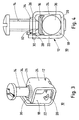
- a connection terminal 10 comprises a cage 12, a screw clamp 14 and a connection pad 16.
- the cage 12 has a one-piece structure produced by cutting and folding a conductive metal strip, so as to form a substantially quadrangular section frame.
- the interior of the cage 12 is provided with a opening 18 delimited by a bottom 20 joined to two vertical branches 22, 24 extending parallel to each other, arm 24 being extended at right angles by an upper branch 26 through which the clamping screw 14 passes.
- the vertical lateral branch 22 is provided at the upper part with a rectangular orifice 28 in which engages a terminal extension 30 in the form of a tenon of the upper branch 26.
- the screw 14 is housed in a tapped hole 32 formed in a collar 34 of the branch upper 26.
- the copper connection pad 16 is housed in the opening 18 of the cage 12 extending parallel to the horizontal branch 26, and is intended to wedge the cable 36 against the bottom 20 when tightening the screw 14.
- connection pad 16 is secured to the end of the rod thread of the screw 14, so as to move in bi-directional vertical translation in the opening 18 during the rotation of the screw 14. If the screw 14 is tightened, the range of connection 16 approaches the fixed bottom 20 causing the cable 36 to jam against it latest.
- connection pad 16 is fixed, and the end of the screw 14 is supported on the upper face of track 16 without being attached to it. If the screw 14, the cage 12 moves upwards, and the bottom 20 wedges the cable 36 against the face lower of range 16.
- the end of the vertical lateral branch 22 projects from the branch 26 horizontal, and the terminal extension 30 is supported on the lower edge of the orifice 28 rectangular by being separated from the upper edge by a first axial clearance J1 when the terminal 10 is in the loose state ( Figures 1 to 3).
- a second transverse J2 game is planned between the internal face of the branch 22 and the two straight edges 38 framing the base of the extension 30, so as to allow the elastic deformation of the cage 12 when tightening screw 14.
- the actuation of the screw 14 causes at the start of tightening an elastic deformation of the cage 12 following the lifting of the terminal extension indicated by the arrow F1.
- This lifting movement is possible thanks to the presence of games J1 and J2, and stops as soon as the terminal extension 30 comes to a stop against the upper edge of the rectangular opening 28.
- the axial clamping force in the cage 12 is relatively moderate during elastic deformation, and is located in the vicinity of a first tightening threshold in a range of 10 to 40 daN.
- the variation of the axial force of tightening during this elastic deformation is represented by the first slope of curve B in FIG. 5.
- the first tightening threshold S1 is reached when the relative displacement of the screw 14 relative to the thread of hole 32 corresponds to the dimension of the first set J1 which is around 0.5mm. This first clamping threshold S1 is perfectly suited to the passage of current between track 16 and cable 36.
- the cage 112 of the terminal 100 comprises, opposite the bottom 120, two end branches 123, 125 superimposed and separated from each other by the first set J1 axial.
- the external curved branch 125 is connected to the vertical lateral branch 124 of straight, and has a smooth circular hole 127 allowing the passage of the screw 14.
- the other internal branch 123 is bent at right angles to the vertical lateral branch 122 of left, and is provided with a tapped hole 132 of smaller diameter for the screw 14.
- the collar 134 is arranged in this case under the underside of the branch 123.
- the second set J2 transverse is provided on the side of the end of the branch 125 between the circular orifice 127 and the barrel of the screw 14.
- the connection range 16 is identical to that of the first embodiment.
- terminal 100 The operation of terminal 100 according to FIGS. 6 to 8 is as follows:
- the horizontal external branch 125 is parallel to the branch 123 internal with a uniform vertical offset corresponding to the first set J1.
- the first tightening threshold S1 is reached at the start of tightening of the screw 14 when the end of the internal branch 123 has caught up with the first set J1, and comes into abutment against the underside of the outer branch 125.
- the first axial clearance J1 adapted to the elastic deformation of the cages 12, 112 extends in the direction of movement of the screw 14.
Landscapes
- Installation Of Indoor Wiring (AREA)
- Connections Effected By Soldering, Adhesion, Or Permanent Deformation (AREA)
- Multi-Conductor Connections (AREA)
- Connections Arranged To Contact A Plurality Of Conductors (AREA)
- Details Of Connecting Devices For Male And Female Coupling (AREA)
- Cable Accessories (AREA)
Abstract
Description
L'invention est relative à une borne de raccordement ayant :
- une cage réalisée par découpage et pliage d'une bande métallique pour former un cadre délimitant une ouverture de section quadrangulaire pour l'insertion d'un câble à raccorder,
- une vis de serrage destinée à serrer le câble entre une plage de connexion et le fond de la cage, ladite vis étant logée dans un trou taraudé ménagé dans une branche supérieure horizontale de ladite cage,
- et deux branches terminales de fermeture du cadre élastique de la cage séparées dans l'état desserré par au moins un premier jeu axial s'étendant dans la direction de déplacement de la vis.
- a cage produced by cutting and folding a metal strip to form a frame delimiting an opening of quadrangular section for the insertion of a cable to be connected,
- a clamping screw intended to clamp the cable between a connection pad and the bottom of the cage, said screw being housed in a tapped hole formed in a horizontal upper branch of said cage,
- and two end branches for closing the elastic frame of the cage separated in the loose state by at least a first axial clearance extending in the direction of movement of the screw.
Les bornes à cages du genre mentionné engendrent des efforts de traction importants au moment du serrage du câble à raccorder. Ces efforts dans la borne peuvent atteindre 300 daN (voir courbe A sur la figure 5), alors que des valeurs dix fois moins importantes seraient suffisantes pour assurer une pression de contact électrique convenable permettant le passage du courant. Une valeur d'effort initial élevé présente l'avantage de provoquer la mise en forme des conducteurs du câble, mais cet effort peut diminuer au fur et à mesure du fluage et de la déformation du métal des conducteurs dans le temps. Il en résulte un effet de desserrage des bornes, entraínant des risques d'échauffement au niveau de la zone de contact.Cage terminals of the kind mentioned generate significant tensile forces when moment of tightening of the cable to be connected. These efforts in the terminal can reach 300 daN (see curve A in Figure 5), while values ten times less important would be sufficient to ensure a suitable electrical contact pressure allowing passage current. A high initial effort value has the advantage of causing shaping of the cable conductors, but this effort can decrease as the creep and the deformation of the metal of the conductors over time. This results in a loosening effect of the terminals, causing risk of overheating in the contact area.
On a déjà proposé des bornes ayant une certaine élasticité pour compenser un éventuel desserrage des vis. Les documents FR-A-2696584 et DE-A-19513281 se rapportent à des bornes à cages équipées d'un ressort de compression destiné à emmagasiner une réserve d'énergie élastique pour assurer un maintien correct du conducteur à raccorder lors d'un léger dévissage de la vis de serrage.We have already proposed terminals having a certain elasticity to compensate for a possible loosening the screws. The documents FR-A-2696584 and DE-A-19513281 relate to cage terminals equipped with a compression spring intended to store a reserve of elastic energy to ensure correct support of the conductor to be connected during a slight unscrewing the clamping screw.
Le document EP 336251 décrit une borne à vis ayant un cadre de serrage et un étrier de fixation disposés perpendiculairement, et autorisant une double connexion d'une plage de contact et d'un fil ou câble. Un intervalle est prévu entre les extrémités du cadre ouvert. Document EP 336251 describes a screw terminal having a clamping frame and a fixing bracket arranged perpendicularly, and allowing a double connection of a contact pad and a wire or cable. A gap is provided between the ends of the open frame.
L'objet de l'invention consiste à réaliser une borne de raccordement à cage élastique garantissant en permanence un bon contact électrique avec le câble sans utiliser de ressort additionnel à l'intérieur de la cage.The object of the invention is to provide an elastic cage connection terminal permanently ensuring good electrical contact with the cable without using a spring additional inside the cage.
Le dispositif selon l'invention est caractérisé en ce que :
- des moyens de butée déterminent un premier seuil de serrage après le rattrapage du premier jeu (J1) en début de serrage de la vis,
- la cage devient plus rigide lors du vissage poursuivi de la vis pour augmenter la force de serrage au-delà dudit premier seuil, et revient ensuite à sa géométrie initiale au desserrage de la vis,
- ladite cage métallique possédant une structure élastique à double pente telle que l'effort axial de traction engendré dans la borne lors du vissage croít plus rapidement dans la deuxième pente que dans la première pente, le passage de la première pente vers le deuxième pente s'effectuant après dépassement du premier seuil de serrage.
- abutment means determine a first tightening threshold after the first clearance (J1) has been taken up at the start of tightening of the screw,
- the cage becomes more rigid during the continued screwing of the screw to increase the tightening force beyond said first threshold, and then returns to its initial geometry when the screw is loosened,
- said metal cage having an elastic structure with a double slope such that the axial tensile force generated in the terminal during screwing increases more rapidly in the second slope than in the first slope, the passage from the first slope to the second slope is performing after exceeding the first tightening threshold.
Une élasticité importante intervient en début de serrage jusqu'à la mise en butée, à partir de laquelle on retrouve le comportement classique d'une cage pour des efforts importants. En cas de léger desserrage de la vis suite au fluage des conducteurs du câble, la cage est sollicitée élastiquement vers l'agencement correspondant au premier seuil de serrage.Significant elasticity occurs at the start of tightening up to the stop, from which we find the classic behavior of a cage for significant efforts. In case slight loosening of the screw due to the creep of the cable conductors, the cage is stressed elastically towards the arrangement corresponding to the first tightening threshold.
Selon un premier mode de réalisation préférentiel, la cage comporte une branche latérale faisant saillie de la branche horizontale terminale supportant la vis, et comprenant un orifice rectangulaire dans lequel s'engage une extension de ladite branche horizontale, laquelle prend appui sur l'arête inférieure de l'orifice rectangulaire en étant séparée de l'arête supérieure par le premier jeu axial lorsque la borne se trouve dans l'état desserré. Un deuxième jeu transversal est prévu entre la face interne de la branche latérale et les deux arêtes rectilignes encadrant la base de l'extension.According to a first preferred embodiment, the cage comprises a lateral branch forming projection of the terminal horizontal branch supporting the screw, and comprising an orifice rectangular in which engages an extension of said horizontal branch, which takes support on the lower edge of the rectangular opening, being separated from the upper edge by the first axial clearance when the bollard is in the loose state. A second transversal game is provided between the internal face of the lateral branch and the two rectilinear edges framing the base of the extension.
Selon un deuxième mode de réalisation, les deux branches terminales de la cage sont superposées à l'opposé du fond en étant séparées par le premier jeu axial. La branche externe est dotée d'un orifice circulaire lisse ayant un diamètre supérieur au trou taraudé ménagé dans la branche interne. Le deuxième jeu transversal est prévu dans ce cas du côté de l'extrémité de la branche externe entre l'orifice circulaire et le fût de la vis, le soulèvement de la branche externe provoquant la venue en engagement contre le fût de la vis lorsqu'un seuil de serrage prédéterminé est atteint, de manière à obtenir un limiteur de couple permettant de générer un effort de serrage constant.According to a second embodiment, the two end branches of the cage are superimposed opposite the bottom, being separated by the first axial clearance. The external branch has a smooth circular opening with a diameter greater than the tapped hole in the internal branch. The second transverse clearance is provided in this case on the side of the end of the external branch between the circular orifice and the barrel of the screw, the lifting of the branch external causing the engagement engagement against the barrel of the screw when a tightening threshold predetermined is reached, so as to obtain a torque limiter making it possible to generate a constant clamping force.
D'autres avantages et caractéristiques ressortiront plus clairement de la description qui va suivre d'un mode de réalisation de l'invention donné à titre d'exemple non limitatif, et représenté aux dessins annexés dans lesquels:
- la figure 1 est une vue en élévation de la borne à cage élastique selon l'invention, la borne étant dans l'état desserré sans la plage de connexion ;
- les figures 2 et 3 montrent des vues en perspective de la borne de la figure 1 ;
- la figure 4 représente une vue identique de la figure 1 lorsque la borne se trouve dans l'état serré ;
- la figure 5 montre les diagrammes de l'effort de serrage en fonction de la déformation d'une borne à cage classique ( courbe A à pente unique), et d'une borne selon l'invention ( courbe B à double pente);
- les figures 6 à 8 sont des vues identiques des figures 1, 2 et 4 d'une variante de réalisation.
- Figure 1 is an elevational view of the elastic cage terminal according to the invention, the terminal being in the loose state without the connection pad;
- Figures 2 and 3 show perspective views of the terminal of Figure 1;
- Figure 4 shows an identical view to Figure 1 when the terminal is in the clamped state;
- FIG. 5 shows the diagrams of the clamping force as a function of the deformation of a conventional cage terminal (curve A with single slope), and of a terminal according to the invention (curve B with double slope);
- Figures 6 to 8 are identical views of Figures 1, 2 and 4 of an alternative embodiment.
En référence aux figures 1 à 4, une borne 10 de raccordement comporte une cage 12, une vis
de serrage 14 et une plage de connexion 16. La cage 12 présente une structure monobloc
réalisée par découpage et pliage d'une bande métallique conductrice, de manière à former un
cadre de section sensiblement quadrangulaire. L'intérieur de la cage 12 est dotée d'une
ouverture 18 délimitée par un fond 20 réuni à deux branches 22, 24 latérales verticales
s'étendant parallèlement l'une par rapport à l'autre, la branche 24 étant prolongée à angle droit
par une branche 26 supérieure traversée par la vis de serrage 14. Referring to Figures 1 to 4, a
La branche latérale 22 verticale est pourvue à la partie supérieure d'un orifice 28 rectangulaire
dans lequel s'engage une extension 30 terminale en forme de tenon de la branche supérieure
26. La vis 14 est logée dans un trou 32 taraudé ménagé dans un collet 34 de la branche
supérieure 26.The vertical
La plage de connexion 16 en cuivre est logée dans l'ouverture 18 de la cage 12 en s'étendant
parallèlement à la branche 26 horizontale, et est destinée à coincer le câble 36 contre le fond 20
lors du serrage de la vis 14.The
Dans le cas d'une cage 12 fixe, la plage de connexion 16 est solidarisée à l'extrémité de la tige
filetée de la vis 14, de manière à se déplacer en translation verticale birectionnelle dans
l'ouverture 18 lors de la rotation de la vis 14. En cas de serrage de la vis 14, la plage de
connexion 16 se rapproche du fond 20 fixe en provoquant le coincement du câble 36 contre ce
dernier.In the case of a
Dans le cas d'une cage 12 mobile, la plage de connexion 16 est fixe, et l'extrémité de la vis 14
prend appui sur la face supérieure de la plage 16 sans y être attachée. En cas de serrage de la
vis 14, la cage 12 se déplace vers le haut, et le fond 20 coince le câble 36 contre la face
inférieure de la plage 16.In the case of a
Selon l'invention, l'extrémité de la branche latérale 22 verticale fait saillie de la branche 26
horizontale, et l'extension 30 terminale prend appui sur l'arête inférieure de l'orifice 28
rectangulaire en étant séparée de l'arête supérieure par un premier jeu J1 axial lorsque la borne
10 se trouve dans l'état desserré ( figures 1 à 3). Un deuxième jeu J2 transversal est prévu entre
la face interne de la branche 22 et les deux arêtes 38 rectilignes encadrant la base de
l'extension 30, de manière à autoriser la déformation élastique de la cage 12 lors du serrage de
la vis 14.According to the invention, the end of the vertical
Pendant la phase de branchement d'un câble 36 illustrée à la figure 4, l'actionnement de la vis
14 provoque en début de serrage une déformation élastique de la cage 12 suite au soulèvement
de l'extension 30 terminale indiqué par la flèche F1. Ce mouvement de soulèvement est possible
grâce à la présence des jeux J1 et J2, et s'arrête dès que l'extension 30 terminale vient en butée
contre l'arête supérieure de l'orifice 28 rectangulaire. L'effort axial de serrage dans la cage 12
est relativement modéré durant la déformation élastique, et est situé au voisinage d'un premier
seuil de serrage se trouvant dans une fourchette de 10 à 40 daN. La variation de l'effort axial de
serrage durant cette déformation élastique est représentée par la première pente de la courbe B
sur la figure 5. Le premier seuil de serrage S1 est atteint lorsque le déplacement relatif de la vis
14 par rapport au taraudage du trou 32 correspond à la dimension du premier jeu J1 qui est de
l'ordre de 0,5mm. Ce premier seuil de serrage S1 est tout à fait adapté au passage du courant
entre la plage 16 et le câble 36.During the connection phase of a
Lorsque le serrage de la vis 14 est poursuivi après la mise en butée de l'extension 30, la cage
12 devient plus rigide, et l'effort axial de traction dans la borne 10 croít rapidement avec la
deuxième pente de la courbe B, laquelle est comparable au comportement d'une cage classique
illustrée par la courbe A. En fonction du couple exercé sur la vis 14, on obtient alors un degré de
serrage intermédiaire situé entre le premier seuil S1 et un deuxième seuil S2 maxi de 300 daN.
La déformation de la cage 12 pendant cette deuxième phase de serrage est inférieure à la
déformation élastique engendrée lors du rattrapage du premier jeu J1.When the tightening of the
La déformation de la cage 12 lors du vissage de la vis 14 se traduit par une fonction de ressort à
double pente. En cas de desserrage suite au tassement et au fluage des conducteurs du câble
36, l'effort axial dans la cage 12 diminue et est ramené vers le premier seuil S1 sur la courbe B.
Cette réserve élastique reste néanmoins suffisante pour maintenir un contact correct entre la
plage 16 et le câble 36.The deformation of the
Sur la variante des figures 6 à 8, la cage 112 de la borne 100 comporte à l'opposé du fond 120,
deux branches d'extrémités 123, 125 superposées et séparées l'une de l'autre par le premier jeu
J1 axial. La branche 125 recourbée externe est reliée à la branche latérale 124 verticale de
droite, et est dotée d'un orifice 127 circulaire lisse autorisant le passage de la vis 14. L'autre
branche 123 interne est pliée en équerre par rapport à la branche latérale 122 verticale de
gauche, et est pourvue d'un trou taraudé 132 de diamètre inférieur pour la vis 14. Le collet 134
est agencé dans ce cas sous la face inférieure de la branche 123. Le deuxième jeu J2
transversal est prévu du côté de l'extrémité de la branche 125 entre l'orifice 127 circulaire et le
fût de la vis 14. La plage de connexion 16 est identique à celle du premier mode de réalisation.In the variant of FIGS. 6 to 8, the
Le fonctionnement de la borne 100 selon les figures 6 à 8 est le suivant : The operation of
Dans l'état desserré de la figure 6, la branche 125 externe horizontale est parallèle à la branche
123 interne avec un décalage vertical uniforme correspondant au premier jeu J1.In the loose state of FIG. 6, the horizontal
Lors du raccordement du câble 36, le premier seuil de serrage S1 est atteint en début de
serrage de la vis 14 lorsque l'extrémité de la branche 123 interne a rattrapé le premier jeu J1, et
arrive en butée contre la face inférieure de la branche 125 externe.When connecting
Sur la figure 8, lorsque le serrage de la vis 14 est poursuivi après la mise en butée de l'extrémité
de la branche 123, la cage 112 devient plus rigide, et l'effort axial de traction dans la borne 100
croít rapidement avec la deuxième pente de la courbe B. Il en résulte un léger soulèvement de la
branche 125 externe dans le sens de la flèche F2, qui est susceptible de venir en engagement
contre le fût de la vis 14 lorsqu'un seuil prédéterminé est atteint. Le vissage de la vis 14 est alors
rendu impossible, et on obtient un limiteur de couple permettant de générer un effort de serrage
constant.In FIG. 8, when the tightening of the
Dans les deux modes de réalisation des figures 1 à 8, le premier jeu J1 axial adapté à la
déformation élastique des cages 12, 112 s'étend dans la direction de déplacement de la vis 14.In the two embodiments of FIGS. 1 to 8, the first axial clearance J1 adapted to the
elastic deformation of the
Claims (7)
Applications Claiming Priority (2)
| Application Number | Priority Date | Filing Date | Title |
|---|---|---|---|
| FR9911694 | 1999-09-15 | ||
| FR9911694A FR2798514B1 (en) | 1999-09-15 | 1999-09-15 | ELASTIC CAGE CONNECTION TERMINAL |
Publications (2)
| Publication Number | Publication Date |
|---|---|
| EP1085601A1 true EP1085601A1 (en) | 2001-03-21 |
| EP1085601B1 EP1085601B1 (en) | 2009-03-18 |
Family
ID=9550006
Family Applications (1)
| Application Number | Title | Priority Date | Filing Date |
|---|---|---|---|
| EP20000410106 Expired - Lifetime EP1085601B1 (en) | 1999-09-15 | 2000-08-30 | Elastic cage-type clamp terminal |
Country Status (6)
| Country | Link |
|---|---|
| EP (1) | EP1085601B1 (en) |
| CN (1) | CN1186855C (en) |
| AR (1) | AR025675A1 (en) |
| DE (1) | DE60041800D1 (en) |
| ES (1) | ES2321273T3 (en) |
| FR (1) | FR2798514B1 (en) |
Cited By (3)
| Publication number | Priority date | Publication date | Assignee | Title |
|---|---|---|---|---|
| EP1531519A1 (en) * | 2003-11-14 | 2005-05-18 | Schneider Electric Industries SAS | Electrical terminal and electrical protection apparatus containing such a terminal |
| EP1825570A1 (en) * | 2004-11-05 | 2007-08-29 | Cooper Technologies Company | Electrical connector |
| FR2997237A1 (en) * | 2012-10-23 | 2014-04-25 | Schneider Electric Ind Sas | ELASTIC CAGE FOR CONNECTING TERMINAL AND TERMINAL COMPRISING SUCH A CAGE |
Families Citing this family (4)
| Publication number | Priority date | Publication date | Assignee | Title |
|---|---|---|---|---|
| CN104332722B (en) * | 2014-10-23 | 2017-01-11 | 江苏海纬电气有限公司 | Special grounding wire clamping component for nuclear power bridge frame |
| CN104347961B (en) * | 2014-11-08 | 2016-08-24 | 钟明华 | Rotary plug-in type four-way cable collection terminal |
| CN107366782B (en) * | 2017-07-31 | 2023-08-15 | 江西清华泰豪三波电机有限公司 | Clamp device |
| FR3090225B1 (en) | 2018-12-13 | 2020-11-27 | Schneider Electric Ind Sas | TERMINAL WITH TIGHTENING COMPENSATION IN PARTICULAR FOR AN ELECTRICAL PROTECTION DEVICE. |
Citations (4)
| Publication number | Priority date | Publication date | Assignee | Title |
|---|---|---|---|---|
| US4072393A (en) * | 1976-06-07 | 1978-02-07 | Mcdermott Robert E | Electrical connectors |
| EP0336251A2 (en) * | 1988-03-31 | 1989-10-11 | Asea Brown Boveri Aktiengesellschaft | Clamping screw |
| FR2696584A1 (en) * | 1992-10-05 | 1994-04-08 | Merlin Gerin | Connection terminal for electrical power equipment. |
| DE19513281A1 (en) * | 1995-04-07 | 1996-10-10 | Kopp Heinrich Ag | Combination terminal-clamp for automatic cut=outs |
-
1999
- 1999-09-15 FR FR9911694A patent/FR2798514B1/en not_active Expired - Fee Related
-
2000
- 2000-08-30 DE DE60041800T patent/DE60041800D1/en not_active Expired - Lifetime
- 2000-08-30 EP EP20000410106 patent/EP1085601B1/en not_active Expired - Lifetime
- 2000-08-30 ES ES00410106T patent/ES2321273T3/en not_active Expired - Lifetime
- 2000-09-14 AR ARP000104838 patent/AR025675A1/en not_active Application Discontinuation
- 2000-09-15 CN CNB001286331A patent/CN1186855C/en not_active Expired - Lifetime
Patent Citations (4)
| Publication number | Priority date | Publication date | Assignee | Title |
|---|---|---|---|---|
| US4072393A (en) * | 1976-06-07 | 1978-02-07 | Mcdermott Robert E | Electrical connectors |
| EP0336251A2 (en) * | 1988-03-31 | 1989-10-11 | Asea Brown Boveri Aktiengesellschaft | Clamping screw |
| FR2696584A1 (en) * | 1992-10-05 | 1994-04-08 | Merlin Gerin | Connection terminal for electrical power equipment. |
| DE19513281A1 (en) * | 1995-04-07 | 1996-10-10 | Kopp Heinrich Ag | Combination terminal-clamp for automatic cut=outs |
Cited By (8)
| Publication number | Priority date | Publication date | Assignee | Title |
|---|---|---|---|---|
| EP1531519A1 (en) * | 2003-11-14 | 2005-05-18 | Schneider Electric Industries SAS | Electrical terminal and electrical protection apparatus containing such a terminal |
| FR2862443A1 (en) * | 2003-11-14 | 2005-05-20 | Schneider Electric Ind Sas | ELECTRICAL CONNECTION TERMINAL AND ELECTRICAL PROTECTION APPARATUS COMPRISING SUCH A TERMINAL |
| EP1825570A1 (en) * | 2004-11-05 | 2007-08-29 | Cooper Technologies Company | Electrical connector |
| EP1825570A4 (en) * | 2004-11-05 | 2008-06-11 | Cooper Technologies Co | Electrical connector |
| FR2997237A1 (en) * | 2012-10-23 | 2014-04-25 | Schneider Electric Ind Sas | ELASTIC CAGE FOR CONNECTING TERMINAL AND TERMINAL COMPRISING SUCH A CAGE |
| EP2725660A1 (en) | 2012-10-23 | 2014-04-30 | Schneider Electric Industries SAS | Flexible tunnel for a connection terminal and terminal comprising one such tunnel |
| US9153881B2 (en) | 2012-10-23 | 2015-10-06 | Schneider Electric Industries Sas | Flexible tunnel for a connection terminal and terminal comprising one such tunnel |
| RU2619072C2 (en) * | 2012-10-23 | 2017-05-11 | Шнейдер Электрик Эндюстри Сас | Flexible tunnel for connecting terminal and terminal comprising such tunnel |
Also Published As
| Publication number | Publication date |
|---|---|
| FR2798514B1 (en) | 2001-11-02 |
| AR025675A1 (en) | 2002-12-11 |
| DE60041800D1 (en) | 2009-04-30 |
| ES2321273T3 (en) | 2009-06-04 |
| FR2798514A1 (en) | 2001-03-16 |
| CN1186855C (en) | 2005-01-26 |
| CN1288273A (en) | 2001-03-21 |
| EP1085601B1 (en) | 2009-03-18 |
Similar Documents
| Publication | Publication Date | Title |
|---|---|---|
| EP2725660B1 (en) | Flexible tunnel for a connection terminal | |
| EP2304848B1 (en) | Electric terminal with a screw, terminal board including such an electric terminal, and electric appliance including such a terminal board | |
| FR2907270A1 (en) | ELECTRICAL APPARATUS FOR FIXING ON A SUPPORT RAIL AND CORRESPONDING MOUNTING METHOD | |
| EP1085601B1 (en) | Elastic cage-type clamp terminal | |
| WO1980002775A1 (en) | Connection device for isolated electric conductors | |
| FR2635615A1 (en) | CONNECTION ACCESSORY FOR CABLE TO BE CONNECTED TO ANY CIRCUIT | |
| FR2663703A1 (en) | BRAKE PAD WEAR SENSOR FOR MOTOR VEHICLES. | |
| EP1531519B1 (en) | Electrical terminal and electrical protection apparatus containing such a terminal | |
| FR2782194A1 (en) | SELF-STRIPPING CONNECTION DEVICE | |
| WO2011033198A1 (en) | Shock absorption device arrangement for a motor vehicle | |
| EP0280672A1 (en) | Electrical installation apparatus connecting terminal | |
| FR2954604A1 (en) | Electrical connecting terminal for use in insulated housing of shaft of e.g. electrical plug, has contact plates with convexities provided on sides of opening of one of arm of clamp spring along guide direction of wire strip of conductor | |
| EP0526324B1 (en) | Cable-clamp | |
| FR2881582A1 (en) | Electrical energy storage battery terminal connector, has hook with lateral arms, where one arm serves as pivot connection and other arm cooperates with notch for disengageable locking of locking unit on locking lug | |
| FR2986664A1 (en) | ELECTRICAL CONNECTION TERMINAL | |
| FR2462031A1 (en) | Battery terminal lead connection - has clamp ring and insulating screw fitting fully over terminal so overall height is not increased | |
| EP4060840A1 (en) | Embeddable electrical appliance | |
| FR2479577A1 (en) | Electrical cable junction block - has spring biassed movable jaw which is releasable by simple screw action of applied tool | |
| EP2730487B1 (en) | Part for holding two elements of a motor vehicle body against one another | |
| FR2720863A1 (en) | Connection box with terminal connection status indicator | |
| FR2752793A1 (en) | Fastening for vehicle roof load=carrying bar | |
| EP0541459A1 (en) | Clamping screw for an electrical device with moulded insulating housing | |
| EP1531525A1 (en) | Cable clamp with enlarged clamping surface and terminal block comprising it | |
| EP0300912B1 (en) | Battery terminal clamp | |
| FR2683683A1 (en) | Cable clamp and electrical apparatus equipped with such a cable clamp |
Legal Events
| Date | Code | Title | Description |
|---|---|---|---|
| PUAI | Public reference made under article 153(3) epc to a published international application that has entered the european phase |
Free format text: ORIGINAL CODE: 0009012 |
|
| AK | Designated contracting states |
Kind code of ref document: A1 Designated state(s): DE ES GB IT SE |
|
| AX | Request for extension of the european patent |
Free format text: AL;LT;LV;MK;RO;SI |
|
| 17P | Request for examination filed |
Effective date: 20010711 |
|
| AKX | Designation fees paid |
Free format text: DE ES GB IT SE |
|
| RAP1 | Party data changed (applicant data changed or rights of an application transferred) |
Owner name: SCHNEIDER ELECTRIC INDUSTRIES SAS |
|
| GRAP | Despatch of communication of intention to grant a patent |
Free format text: ORIGINAL CODE: EPIDOSNIGR1 |
|
| GRAS | Grant fee paid |
Free format text: ORIGINAL CODE: EPIDOSNIGR3 |
|
| GRAA | (expected) grant |
Free format text: ORIGINAL CODE: 0009210 |
|
| AK | Designated contracting states |
Kind code of ref document: B1 Designated state(s): DE ES GB IT SE |
|
| REG | Reference to a national code |
Ref country code: GB Ref legal event code: FG4D Free format text: NOT ENGLISH |
|
| RAP2 | Party data changed (patent owner data changed or rights of a patent transferred) |
Owner name: SCHNEIDER ELECTRIC INDUSTRIES SAS |
|
| REF | Corresponds to: |
Ref document number: 60041800 Country of ref document: DE Date of ref document: 20090430 Kind code of ref document: P |
|
| REG | Reference to a national code |
Ref country code: ES Ref legal event code: FG2A Ref document number: 2321273 Country of ref document: ES Kind code of ref document: T3 |
|
| REG | Reference to a national code |
Ref country code: SE Ref legal event code: TRGR |
|
| PLBE | No opposition filed within time limit |
Free format text: ORIGINAL CODE: 0009261 |
|
| STAA | Information on the status of an ep patent application or granted ep patent |
Free format text: STATUS: NO OPPOSITION FILED WITHIN TIME LIMIT |
|
| 26N | No opposition filed |
Effective date: 20091221 |
|
| REG | Reference to a national code |
Ref country code: DE Ref legal event code: R084 Ref document number: 60041800 Country of ref document: DE Effective date: 20111228 |
|
| PGFP | Annual fee paid to national office [announced via postgrant information from national office to epo] |
Ref country code: IT Payment date: 20160822 Year of fee payment: 17 Ref country code: GB Payment date: 20160824 Year of fee payment: 17 Ref country code: DE Payment date: 20160701 Year of fee payment: 17 |
|
| PGFP | Annual fee paid to national office [announced via postgrant information from national office to epo] |
Ref country code: SE Payment date: 20160811 Year of fee payment: 17 |
|
| PGFP | Annual fee paid to national office [announced via postgrant information from national office to epo] |
Ref country code: ES Payment date: 20160712 Year of fee payment: 17 |
|
| REG | Reference to a national code |
Ref country code: DE Ref legal event code: R119 Ref document number: 60041800 Country of ref document: DE |
|
| GBPC | Gb: european patent ceased through non-payment of renewal fee |
Effective date: 20170830 |
|
| PG25 | Lapsed in a contracting state [announced via postgrant information from national office to epo] |
Ref country code: SE Free format text: LAPSE BECAUSE OF NON-PAYMENT OF DUE FEES Effective date: 20170831 |
|
| PG25 | Lapsed in a contracting state [announced via postgrant information from national office to epo] |
Ref country code: DE Free format text: LAPSE BECAUSE OF NON-PAYMENT OF DUE FEES Effective date: 20180301 Ref country code: GB Free format text: LAPSE BECAUSE OF NON-PAYMENT OF DUE FEES Effective date: 20170830 |
|
| PG25 | Lapsed in a contracting state [announced via postgrant information from national office to epo] |
Ref country code: IT Free format text: LAPSE BECAUSE OF NON-PAYMENT OF DUE FEES Effective date: 20170830 |
|
| REG | Reference to a national code |
Ref country code: ES Ref legal event code: FD2A Effective date: 20181024 |
|
| PG25 | Lapsed in a contracting state [announced via postgrant information from national office to epo] |
Ref country code: ES Free format text: LAPSE BECAUSE OF NON-PAYMENT OF DUE FEES Effective date: 20170831 |