EP1085601A1 - Elastische Käfigklemme - Google Patents
Elastische Käfigklemme Download PDFInfo
- Publication number
- EP1085601A1 EP1085601A1 EP00410106A EP00410106A EP1085601A1 EP 1085601 A1 EP1085601 A1 EP 1085601A1 EP 00410106 A EP00410106 A EP 00410106A EP 00410106 A EP00410106 A EP 00410106A EP 1085601 A1 EP1085601 A1 EP 1085601A1
- Authority
- EP
- European Patent Office
- Prior art keywords
- cage
- screw
- branch
- connection terminal
- slope
- Prior art date
- Legal status (The legal status is an assumption and is not a legal conclusion. Google has not performed a legal analysis and makes no representation as to the accuracy of the status listed.)
- Granted
Links
Images


Classifications
-
- H—ELECTRICITY
- H01—ELECTRIC ELEMENTS
- H01R—ELECTRICALLY-CONDUCTIVE CONNECTIONS; STRUCTURAL ASSOCIATIONS OF A PLURALITY OF MUTUALLY-INSULATED ELECTRICAL CONNECTING ELEMENTS; COUPLING DEVICES; CURRENT COLLECTORS
- H01R4/00—Electrically-conductive connections between two or more conductive members in direct contact, i.e. touching one another; Means for effecting or maintaining such contact; Electrically-conductive connections having two or more spaced connecting locations for conductors and using contact members penetrating insulation
- H01R4/28—Clamped connections, spring connections
- H01R4/38—Clamped connections, spring connections utilising a clamping member acted on by screw or nut
-
- H—ELECTRICITY
- H01—ELECTRIC ELEMENTS
- H01R—ELECTRICALLY-CONDUCTIVE CONNECTIONS; STRUCTURAL ASSOCIATIONS OF A PLURALITY OF MUTUALLY-INSULATED ELECTRICAL CONNECTING ELEMENTS; COUPLING DEVICES; CURRENT COLLECTORS
- H01R4/00—Electrically-conductive connections between two or more conductive members in direct contact, i.e. touching one another; Means for effecting or maintaining such contact; Electrically-conductive connections having two or more spaced connecting locations for conductors and using contact members penetrating insulation
- H01R4/28—Clamped connections, spring connections
- H01R4/30—Clamped connections, spring connections utilising a screw or nut clamping member
- H01R4/36—Conductive members located under tip of screw
- H01R4/363—Conductive members located under tip of screw with intermediate part between tip and conductive member
Definitions
- Cage terminals of the kind mentioned generate significant tensile forces when moment of tightening of the cable to be connected. These efforts in the terminal can reach 300 daN (see curve A in Figure 5), while values ten times less important would be sufficient to ensure a suitable electrical contact pressure allowing passage current.
- a high initial effort value has the advantage of causing shaping of the cable conductors, but this effort can decrease as the creep and the deformation of the metal of the conductors over time. This results in a loosening effect of the terminals, causing risk of overheating in the contact area.
- the documents FR-A-2696584 and DE-A-19513281 relate to cage terminals equipped with a compression spring intended to store a reserve of elastic energy to ensure correct support of the conductor to be connected during a slight unscrewing the clamping screw.
- Document EP 336251 describes a screw terminal having a clamping frame and a fixing bracket arranged perpendicularly, and allowing a double connection of a contact pad and a wire or cable. A gap is provided between the ends of the open frame.
- the object of the invention is to provide an elastic cage connection terminal permanently ensuring good electrical contact with the cable without using a spring additional inside the cage.
- the cage comprises a lateral branch forming projection of the terminal horizontal branch supporting the screw, and comprising an orifice rectangular in which engages an extension of said horizontal branch, which takes support on the lower edge of the rectangular opening, being separated from the upper edge by the first axial clearance when the bollard is in the loose state.
- a second transversal game is provided between the internal face of the lateral branch and the two rectilinear edges framing the base of the extension.
- the two end branches of the cage are superimposed opposite the bottom, being separated by the first axial clearance.
- the external branch has a smooth circular opening with a diameter greater than the tapped hole in the internal branch.
- the second transverse clearance is provided in this case on the side of the end of the external branch between the circular orifice and the barrel of the screw, the lifting of the branch external causing the engagement engagement against the barrel of the screw when a tightening threshold predetermined is reached, so as to obtain a torque limiter making it possible to generate a constant clamping force.
- a connection terminal 10 comprises a cage 12, a screw clamp 14 and a connection pad 16.
- the cage 12 has a one-piece structure produced by cutting and folding a conductive metal strip, so as to form a substantially quadrangular section frame.
- the interior of the cage 12 is provided with a opening 18 delimited by a bottom 20 joined to two vertical branches 22, 24 extending parallel to each other, arm 24 being extended at right angles by an upper branch 26 through which the clamping screw 14 passes.
- the vertical lateral branch 22 is provided at the upper part with a rectangular orifice 28 in which engages a terminal extension 30 in the form of a tenon of the upper branch 26.
- the screw 14 is housed in a tapped hole 32 formed in a collar 34 of the branch upper 26.
- the copper connection pad 16 is housed in the opening 18 of the cage 12 extending parallel to the horizontal branch 26, and is intended to wedge the cable 36 against the bottom 20 when tightening the screw 14.
- connection pad 16 is secured to the end of the rod thread of the screw 14, so as to move in bi-directional vertical translation in the opening 18 during the rotation of the screw 14. If the screw 14 is tightened, the range of connection 16 approaches the fixed bottom 20 causing the cable 36 to jam against it latest.
- connection pad 16 is fixed, and the end of the screw 14 is supported on the upper face of track 16 without being attached to it. If the screw 14, the cage 12 moves upwards, and the bottom 20 wedges the cable 36 against the face lower of range 16.
- the end of the vertical lateral branch 22 projects from the branch 26 horizontal, and the terminal extension 30 is supported on the lower edge of the orifice 28 rectangular by being separated from the upper edge by a first axial clearance J1 when the terminal 10 is in the loose state ( Figures 1 to 3).
- a second transverse J2 game is planned between the internal face of the branch 22 and the two straight edges 38 framing the base of the extension 30, so as to allow the elastic deformation of the cage 12 when tightening screw 14.
- the actuation of the screw 14 causes at the start of tightening an elastic deformation of the cage 12 following the lifting of the terminal extension indicated by the arrow F1.
- This lifting movement is possible thanks to the presence of games J1 and J2, and stops as soon as the terminal extension 30 comes to a stop against the upper edge of the rectangular opening 28.
- the axial clamping force in the cage 12 is relatively moderate during elastic deformation, and is located in the vicinity of a first tightening threshold in a range of 10 to 40 daN.
- the variation of the axial force of tightening during this elastic deformation is represented by the first slope of curve B in FIG. 5.
- the first tightening threshold S1 is reached when the relative displacement of the screw 14 relative to the thread of hole 32 corresponds to the dimension of the first set J1 which is around 0.5mm. This first clamping threshold S1 is perfectly suited to the passage of current between track 16 and cable 36.
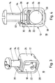
- the cage 112 of the terminal 100 comprises, opposite the bottom 120, two end branches 123, 125 superimposed and separated from each other by the first set J1 axial.
- the external curved branch 125 is connected to the vertical lateral branch 124 of straight, and has a smooth circular hole 127 allowing the passage of the screw 14.
- the other internal branch 123 is bent at right angles to the vertical lateral branch 122 of left, and is provided with a tapped hole 132 of smaller diameter for the screw 14.
- the collar 134 is arranged in this case under the underside of the branch 123.
- the second set J2 transverse is provided on the side of the end of the branch 125 between the circular orifice 127 and the barrel of the screw 14.
- the connection range 16 is identical to that of the first embodiment.
- terminal 100 The operation of terminal 100 according to FIGS. 6 to 8 is as follows:
- the horizontal external branch 125 is parallel to the branch 123 internal with a uniform vertical offset corresponding to the first set J1.
- the first tightening threshold S1 is reached at the start of tightening of the screw 14 when the end of the internal branch 123 has caught up with the first set J1, and comes into abutment against the underside of the outer branch 125.
- the first axial clearance J1 adapted to the elastic deformation of the cages 12, 112 extends in the direction of movement of the screw 14.
Applications Claiming Priority (2)
| Application Number | Priority Date | Filing Date | Title |
|---|---|---|---|
| FR9911694A FR2798514B1 (fr) | 1999-09-15 | 1999-09-15 | Borne de raccordement a cage elastique |
| FR9911694 | 1999-09-15 |
Publications (2)
| Publication Number | Publication Date |
|---|---|
| EP1085601A1 true EP1085601A1 (de) | 2001-03-21 |
| EP1085601B1 EP1085601B1 (de) | 2009-03-18 |
Family
ID=9550006
Family Applications (1)
| Application Number | Title | Priority Date | Filing Date |
|---|---|---|---|
| EP20000410106 Expired - Lifetime EP1085601B1 (de) | 1999-09-15 | 2000-08-30 | Elastische Käfigklemme |
Country Status (6)
| Country | Link |
|---|---|
| EP (1) | EP1085601B1 (de) |
| CN (1) | CN1186855C (de) |
| AR (1) | AR025675A1 (de) |
| DE (1) | DE60041800D1 (de) |
| ES (1) | ES2321273T3 (de) |
| FR (1) | FR2798514B1 (de) |
Cited By (3)
| Publication number | Priority date | Publication date | Assignee | Title |
|---|---|---|---|---|
| EP1531519A1 (de) * | 2003-11-14 | 2005-05-18 | Schneider Electric Industries SAS | Elektrische Anschlussklemme und elektrisches Schutzgerät mit einer solchen Klemme |
| EP1825570A1 (de) * | 2004-11-05 | 2007-08-29 | Cooper Technologies Company | Elektrischer verbinder |
| FR2997237A1 (fr) * | 2012-10-23 | 2014-04-25 | Schneider Electric Ind Sas | Cage elastique pour borne de raccordement et borne comportant une telle cage |
Families Citing this family (4)
| Publication number | Priority date | Publication date | Assignee | Title |
|---|---|---|---|---|
| CN104332722B (zh) * | 2014-10-23 | 2017-01-11 | 江苏海纬电气有限公司 | 一种核电桥架专用的接地线卡紧部件 |
| CN104347961B (zh) * | 2014-11-08 | 2016-08-24 | 钟明华 | 旋插式四向电缆集线柱 |
| CN107366782B (zh) * | 2017-07-31 | 2023-08-15 | 江西清华泰豪三波电机有限公司 | 一种卡箍装置 |
| FR3090225B1 (fr) | 2018-12-13 | 2020-11-27 | Schneider Electric Ind Sas | Borne a compensation de serrage en particulier pour un appareil de protection electrique. |
Citations (4)
| Publication number | Priority date | Publication date | Assignee | Title |
|---|---|---|---|---|
| US4072393A (en) * | 1976-06-07 | 1978-02-07 | Mcdermott Robert E | Electrical connectors |
| EP0336251A2 (de) * | 1988-03-31 | 1989-10-11 | Asea Brown Boveri Aktiengesellschaft | Schraubklemme |
| FR2696584A1 (fr) * | 1992-10-05 | 1994-04-08 | Merlin Gerin | Borne de raccordement pour appareillage électrique de puissance. |
| DE19513281A1 (de) * | 1995-04-07 | 1996-10-10 | Kopp Heinrich Ag | Kombianschlußklemme |
-
1999
- 1999-09-15 FR FR9911694A patent/FR2798514B1/fr not_active Expired - Fee Related
-
2000
- 2000-08-30 ES ES00410106T patent/ES2321273T3/es not_active Expired - Lifetime
- 2000-08-30 DE DE60041800T patent/DE60041800D1/de not_active Expired - Lifetime
- 2000-08-30 EP EP20000410106 patent/EP1085601B1/de not_active Expired - Lifetime
- 2000-09-14 AR ARP000104838 patent/AR025675A1/es not_active Application Discontinuation
- 2000-09-15 CN CNB001286331A patent/CN1186855C/zh not_active Expired - Lifetime
Patent Citations (4)
| Publication number | Priority date | Publication date | Assignee | Title |
|---|---|---|---|---|
| US4072393A (en) * | 1976-06-07 | 1978-02-07 | Mcdermott Robert E | Electrical connectors |
| EP0336251A2 (de) * | 1988-03-31 | 1989-10-11 | Asea Brown Boveri Aktiengesellschaft | Schraubklemme |
| FR2696584A1 (fr) * | 1992-10-05 | 1994-04-08 | Merlin Gerin | Borne de raccordement pour appareillage électrique de puissance. |
| DE19513281A1 (de) * | 1995-04-07 | 1996-10-10 | Kopp Heinrich Ag | Kombianschlußklemme |
Cited By (8)
| Publication number | Priority date | Publication date | Assignee | Title |
|---|---|---|---|---|
| EP1531519A1 (de) * | 2003-11-14 | 2005-05-18 | Schneider Electric Industries SAS | Elektrische Anschlussklemme und elektrisches Schutzgerät mit einer solchen Klemme |
| FR2862443A1 (fr) * | 2003-11-14 | 2005-05-20 | Schneider Electric Ind Sas | Borne de raccordement electrique et appareil de protection electrique comportant une telle borne |
| EP1825570A1 (de) * | 2004-11-05 | 2007-08-29 | Cooper Technologies Company | Elektrischer verbinder |
| EP1825570A4 (de) * | 2004-11-05 | 2008-06-11 | Cooper Technologies Co | Elektrischer verbinder |
| FR2997237A1 (fr) * | 2012-10-23 | 2014-04-25 | Schneider Electric Ind Sas | Cage elastique pour borne de raccordement et borne comportant une telle cage |
| EP2725660A1 (de) | 2012-10-23 | 2014-04-30 | Schneider Electric Industries SAS | Elastisches Gehäuse für Anschlussklemme |
| US9153881B2 (en) | 2012-10-23 | 2015-10-06 | Schneider Electric Industries Sas | Flexible tunnel for a connection terminal and terminal comprising one such tunnel |
| RU2619072C2 (ru) * | 2012-10-23 | 2017-05-11 | Шнейдер Электрик Эндюстри Сас | Гибкий туннель для соединительной клеммы и клемма, содержащая такой туннель |
Also Published As
| Publication number | Publication date |
|---|---|
| CN1186855C (zh) | 2005-01-26 |
| CN1288273A (zh) | 2001-03-21 |
| EP1085601B1 (de) | 2009-03-18 |
| AR025675A1 (es) | 2002-12-11 |
| DE60041800D1 (de) | 2009-04-30 |
| FR2798514B1 (fr) | 2001-11-02 |
| FR2798514A1 (fr) | 2001-03-16 |
| ES2321273T3 (es) | 2009-06-04 |
Similar Documents
| Publication | Publication Date | Title |
|---|---|---|
| EP2725660B1 (de) | Elastisches Gehäuse für Anschlussklemme | |
| EP2304848B1 (de) | Elektrische klemme mit einer schraube, klemmentafel mit einer solchen elektrischen klemme und elektrische anwendung mit einer solchen klemmentafel | |
| FR2907270A1 (fr) | Appareil electrique,destine a etre fixe sur un rail support, et procede de montage correspondant | |
| EP1085601B1 (de) | Elastische Käfigklemme | |
| WO1980002775A1 (fr) | Dispositif de raccordement de conducteurs electriques isoles | |
| FR2635615A1 (fr) | Accessoire de branchement pour cable a relier a un quelconque circuit | |
| FR2663703A1 (fr) | Capteur d'usure de plaquette de frein pour vehicules automobiles. | |
| EP1531519B1 (de) | Elektrische Anschlussklemme und elektrisches Schutzgerät mit einer solchen Klemme | |
| FR2954604A1 (fr) | Borne de connexion electrique automatique et appareillage electrique comportant une telle borne | |
| FR2782194A1 (fr) | Dispositif de connexion auto-denudant | |
| WO2011033198A1 (fr) | Agencement d'un dispositif d'absorption de chocs pour vehicule automobile | |
| EP0280672A1 (de) | Verbindungsklemme für elektrisches Einrichtungsgerät | |
| EP0526324B1 (de) | Kabelklemme | |
| FR2881582A1 (fr) | Connecteur pour borne de batterie | |
| FR2986664A1 (fr) | Borne de raccordement electrique | |
| FR2462031A1 (fr) | Dispositif de connexion plus particulierement destine aux batteries d'accumulateur | |
| EP4060840A1 (de) | Elektrisches einbaugerät | |
| FR2479577A1 (fr) | Connecteur electrique | |
| EP2730487B1 (de) | Haltebauteil für zwei gegeneinander befestigte Karosserieelemente eines Kraftfahrzeugs | |
| FR2720863A1 (fr) | Appareil électrique à borne de connexion équipé d'un voyant, tel que bloc de jonction ou autre. | |
| FR2752793A1 (fr) | Dispositif pour fixer une barre porte-charge sur le toit d'un vehicule automobile | |
| EP0541459A1 (de) | Schraubklemme für elektrisches Gerät mit gegossenem Isoliergehäuse | |
| EP1531525A1 (de) | Kabelklemme mit vergrösserter Klemmfläche und damit ausgerüsteter Verbinderblock | |
| EP0300912B1 (de) | Anschlussklemme für Batterie | |
| FR2683683A1 (fr) | Serre-cable et appareil electrique equipe d'un tel serre-cable. |
Legal Events
| Date | Code | Title | Description |
|---|---|---|---|
| PUAI | Public reference made under article 153(3) epc to a published international application that has entered the european phase |
Free format text: ORIGINAL CODE: 0009012 |
|
| AK | Designated contracting states |
Kind code of ref document: A1 Designated state(s): DE ES GB IT SE |
|
| AX | Request for extension of the european patent |
Free format text: AL;LT;LV;MK;RO;SI |
|
| 17P | Request for examination filed |
Effective date: 20010711 |
|
| AKX | Designation fees paid |
Free format text: DE ES GB IT SE |
|
| RAP1 | Party data changed (applicant data changed or rights of an application transferred) |
Owner name: SCHNEIDER ELECTRIC INDUSTRIES SAS |
|
| GRAP | Despatch of communication of intention to grant a patent |
Free format text: ORIGINAL CODE: EPIDOSNIGR1 |
|
| GRAS | Grant fee paid |
Free format text: ORIGINAL CODE: EPIDOSNIGR3 |
|
| GRAA | (expected) grant |
Free format text: ORIGINAL CODE: 0009210 |
|
| AK | Designated contracting states |
Kind code of ref document: B1 Designated state(s): DE ES GB IT SE |
|
| REG | Reference to a national code |
Ref country code: GB Ref legal event code: FG4D Free format text: NOT ENGLISH |
|
| RAP2 | Party data changed (patent owner data changed or rights of a patent transferred) |
Owner name: SCHNEIDER ELECTRIC INDUSTRIES SAS |
|
| REF | Corresponds to: |
Ref document number: 60041800 Country of ref document: DE Date of ref document: 20090430 Kind code of ref document: P |
|
| REG | Reference to a national code |
Ref country code: ES Ref legal event code: FG2A Ref document number: 2321273 Country of ref document: ES Kind code of ref document: T3 |
|
| REG | Reference to a national code |
Ref country code: SE Ref legal event code: TRGR |
|
| PLBE | No opposition filed within time limit |
Free format text: ORIGINAL CODE: 0009261 |
|
| STAA | Information on the status of an ep patent application or granted ep patent |
Free format text: STATUS: NO OPPOSITION FILED WITHIN TIME LIMIT |
|
| 26N | No opposition filed |
Effective date: 20091221 |
|
| REG | Reference to a national code |
Ref country code: DE Ref legal event code: R084 Ref document number: 60041800 Country of ref document: DE Effective date: 20111228 |
|
| PGFP | Annual fee paid to national office [announced via postgrant information from national office to epo] |
Ref country code: IT Payment date: 20160822 Year of fee payment: 17 Ref country code: GB Payment date: 20160824 Year of fee payment: 17 Ref country code: DE Payment date: 20160701 Year of fee payment: 17 |
|
| PGFP | Annual fee paid to national office [announced via postgrant information from national office to epo] |
Ref country code: SE Payment date: 20160811 Year of fee payment: 17 |
|
| PGFP | Annual fee paid to national office [announced via postgrant information from national office to epo] |
Ref country code: ES Payment date: 20160712 Year of fee payment: 17 |
|
| REG | Reference to a national code |
Ref country code: DE Ref legal event code: R119 Ref document number: 60041800 Country of ref document: DE |
|
| GBPC | Gb: european patent ceased through non-payment of renewal fee |
Effective date: 20170830 |
|
| PG25 | Lapsed in a contracting state [announced via postgrant information from national office to epo] |
Ref country code: SE Free format text: LAPSE BECAUSE OF NON-PAYMENT OF DUE FEES Effective date: 20170831 |
|
| PG25 | Lapsed in a contracting state [announced via postgrant information from national office to epo] |
Ref country code: DE Free format text: LAPSE BECAUSE OF NON-PAYMENT OF DUE FEES Effective date: 20180301 Ref country code: GB Free format text: LAPSE BECAUSE OF NON-PAYMENT OF DUE FEES Effective date: 20170830 |
|
| PG25 | Lapsed in a contracting state [announced via postgrant information from national office to epo] |
Ref country code: IT Free format text: LAPSE BECAUSE OF NON-PAYMENT OF DUE FEES Effective date: 20170830 |
|
| REG | Reference to a national code |
Ref country code: ES Ref legal event code: FD2A Effective date: 20181024 |
|
| PG25 | Lapsed in a contracting state [announced via postgrant information from national office to epo] |
Ref country code: ES Free format text: LAPSE BECAUSE OF NON-PAYMENT OF DUE FEES Effective date: 20170831 |