EP1084055B1 - Procede de realisation d'une carrosserie automobile - Google Patents
Procede de realisation d'une carrosserie automobile Download PDFInfo
- Publication number
- EP1084055B1 EP1084055B1 EP99922243A EP99922243A EP1084055B1 EP 1084055 B1 EP1084055 B1 EP 1084055B1 EP 99922243 A EP99922243 A EP 99922243A EP 99922243 A EP99922243 A EP 99922243A EP 1084055 B1 EP1084055 B1 EP 1084055B1
- Authority
- EP
- European Patent Office
- Prior art keywords
- frame
- tools
- underbody
- sides
- station
- Prior art date
- Legal status (The legal status is an assumption and is not a legal conclusion. Google has not performed a legal analysis and makes no representation as to the accuracy of the status listed.)
- Expired - Lifetime
Links
Images

Classifications
-
- B—PERFORMING OPERATIONS; TRANSPORTING
- B62—LAND VEHICLES FOR TRAVELLING OTHERWISE THAN ON RAILS
- B62D—MOTOR VEHICLES; TRAILERS
- B62D65/00—Designing, manufacturing, e.g. assembling, facilitating disassembly, or structurally modifying motor vehicles or trailers, not otherwise provided for
-
- Y—GENERAL TAGGING OF NEW TECHNOLOGICAL DEVELOPMENTS; GENERAL TAGGING OF CROSS-SECTIONAL TECHNOLOGIES SPANNING OVER SEVERAL SECTIONS OF THE IPC; TECHNICAL SUBJECTS COVERED BY FORMER USPC CROSS-REFERENCE ART COLLECTIONS [XRACs] AND DIGESTS
- Y10—TECHNICAL SUBJECTS COVERED BY FORMER USPC
- Y10T—TECHNICAL SUBJECTS COVERED BY FORMER US CLASSIFICATION
- Y10T29/00—Metal working
- Y10T29/49—Method of mechanical manufacture
- Y10T29/49616—Structural member making
- Y10T29/49622—Vehicular structural member making
-
- Y—GENERAL TAGGING OF NEW TECHNOLOGICAL DEVELOPMENTS; GENERAL TAGGING OF CROSS-SECTIONAL TECHNOLOGIES SPANNING OVER SEVERAL SECTIONS OF THE IPC; TECHNICAL SUBJECTS COVERED BY FORMER USPC CROSS-REFERENCE ART COLLECTIONS [XRACs] AND DIGESTS
- Y10—TECHNICAL SUBJECTS COVERED BY FORMER USPC
- Y10T—TECHNICAL SUBJECTS COVERED BY FORMER US CLASSIFICATION
- Y10T29/00—Metal working
- Y10T29/49—Method of mechanical manufacture
- Y10T29/49826—Assembling or joining
- Y10T29/49895—Associating parts by use of aligning means [e.g., use of a drift pin or a "fixture"]
- Y10T29/49899—Associating parts by use of aligning means [e.g., use of a drift pin or a "fixture"] by multiple cooperating aligning means
-
- Y—GENERAL TAGGING OF NEW TECHNOLOGICAL DEVELOPMENTS; GENERAL TAGGING OF CROSS-SECTIONAL TECHNOLOGIES SPANNING OVER SEVERAL SECTIONS OF THE IPC; TECHNICAL SUBJECTS COVERED BY FORMER USPC CROSS-REFERENCE ART COLLECTIONS [XRACs] AND DIGESTS
- Y10—TECHNICAL SUBJECTS COVERED BY FORMER USPC
- Y10T—TECHNICAL SUBJECTS COVERED BY FORMER US CLASSIFICATION
- Y10T29/00—Metal working
- Y10T29/49—Method of mechanical manufacture
- Y10T29/49998—Work holding
-
- Y—GENERAL TAGGING OF NEW TECHNOLOGICAL DEVELOPMENTS; GENERAL TAGGING OF CROSS-SECTIONAL TECHNOLOGIES SPANNING OVER SEVERAL SECTIONS OF THE IPC; TECHNICAL SUBJECTS COVERED BY FORMER USPC CROSS-REFERENCE ART COLLECTIONS [XRACs] AND DIGESTS
- Y10—TECHNICAL SUBJECTS COVERED BY FORMER USPC
- Y10T—TECHNICAL SUBJECTS COVERED BY FORMER US CLASSIFICATION
- Y10T29/00—Metal working
- Y10T29/53—Means to assemble or disassemble
- Y10T29/53961—Means to assemble or disassemble with work-holder for assembly
-
- Y—GENERAL TAGGING OF NEW TECHNOLOGICAL DEVELOPMENTS; GENERAL TAGGING OF CROSS-SECTIONAL TECHNOLOGIES SPANNING OVER SEVERAL SECTIONS OF THE IPC; TECHNICAL SUBJECTS COVERED BY FORMER USPC CROSS-REFERENCE ART COLLECTIONS [XRACs] AND DIGESTS
- Y10—TECHNICAL SUBJECTS COVERED BY FORMER USPC
- Y10T—TECHNICAL SUBJECTS COVERED BY FORMER US CLASSIFICATION
- Y10T29/00—Metal working
- Y10T29/53—Means to assemble or disassemble
- Y10T29/53983—Work-supported apparatus
Definitions
- the present invention relates to a method of realization of an automobile body allowing to lighten tools as much as possible in assembly stations in order to authorize the use of robots as tools for geometry of the bodywork at the welding station and / or tools for handling body sub-assemblies to assemble.
- the body enters pre-stapled into a post and the tools maintain this bodywork in geometry.
- the bodywork is brought into a substation by subassemblies by means of chassis and these are maintained in geometry either as before by tools belonging to the welding stations, either by a interlocation of the chassis with respect to others on a basis which is itself referenced in the welding station.
- FIG. 1 To illustrate the main subsets that constitute a vehicle body, see Figure 1 in which there is shown a base 1 which forms the lower structure of the body with at the front an engine compartment 2 which is a structure in box having in itself a relatively stiffness important.
- FIG. 1 Another subset consists of a skirt rear 3 and intended to be fixed to the base and to the rear part of two body sides such as 4 (only one is shown in Figure 1), these sides of the body being also assembled laterally to the base 1.
- a fourth group of elements comprising a roof panel 5 and two crosspieces 6 and 7 extend between the two sides of the body and more exactly between the two upper parts of these body sides such as 4 called stretchers.
- the base reaches alone at the welding station on a basis in which he is referenced and which is itself placed precisely in the job repository, while the other subsets are each associated with a chassis (generally a frame with clamps for fixing the subassemblies) which are assembled on the base and positioned in relation to this either by means of external tools belonging to a general frame either by mutual interlocking to form a "rigid" non-deformable box in which the sub-assemblies are in correct position with respect to other and compared to the welding robot to be welded.
- WO-95/19868 describes a method and the associated device for setting relative positioning of automobile body elements, presenting the primary steps of the method claimed in claim 1 of the this request without, however, using means of bracing.
- the present invention arises from observation according to which the greatest difficulties in geometry of a motor vehicle body are located the end of the base opposite the engine compartment, that is to say in a place where the base itself is relatively deformable.
- the compartment side driving this base we realized that could be useful, if not sufficient, to take advantage of the stiffness of it since this engine compartment is in almost indeformable box shape, at least facing efforts made to maintain the sub-assemblies assembled in a welding station before or at during welding.
- the subject of the present invention is a process for producing an automobile body comprising at least one step of assembling a base with body sides, the base comprising a rigid engine compartment at one end and being placed in a determined position in an orthogonal coordinate system of directions X Y Z of an assembly station, process which consists of implementing and maintaining position of the body sides in the position marker at by means of two parallel tools each cooperating with a body side and at least one tool transverse to these parallel tools, the three tools being linked to each other others and to the job repository so that the tool transverse either place and held in one position precise and locked in this mark and that it forms a bracing and bracing tool in the Y direction for two parallel tools in an area away from the underbody engine compartment, this process further consisting in maintaining an effort to apply each of the parallel tools at least against the sides side of the engine compartment of the underbody during the assembly of the sides of the body to this base.
- a operating mode could be as follows: the transverse tool is approached from the pre-assembled body for take charge of the rear apron if it exists, and then be completely immobilized in the frame of the post; then the parallel side tools are approached body sides they support and stiffen by means of the grippers which they comprise for this purpose in a known manner and then are immobilized in the X and Z directions on supports that the post, or even for one or other of these fixed assets through the transverse tool and in Y by cooperation with the transversal tool by one of their ends while a pushing means is put into service towards their other end close to the engine compartment to press the sides of the body against this compartment.
- This pushing means can be a simple cylinder extending between the post and each of the side tools while being able to be erased at the time of docking or removal of these tools.
- the tools constitute supports for the rear skirt and body sides for example, and are brought in to these sub-assemblies in the welding station where they are put in place for example as previously mentioned.
- lateral tools fitted on the side of their end close to the engine compartment elements of mutual support that come into contact with each other under the thrust in the Y direction they undergo, if the rigidity of the compartment engine would be deemed insufficient, or to prevent a too much crushing of this engine compartment between the two tools.
- These support elements may include locked bonding means that could relieve the thrust cylinders of the force effect on the bodywork tending to separate the sides of the body from one another.
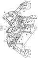
- FIG. 2 there is shown at 10 a fixed frame of a vehicle body assembly station which has a reference X, Y, Z.
- this frame can be provided a support for the base 1 of a body of motor vehicle.
- the means for providing this support and placing it in position in the frame X, Y, Z are known in themselves and are not shown.
- This support can for example be constituted by a pallet which circulates by means of a conveyor passing through the frame 10 along the direction X, elevation means being provided in the frame to separate the pallet from the conveyor and put it in reference in the frame X, Y, Z.
- a transverse tool within the meaning of the method according to the invention is symbolized in the form of a frame 11 transverse to the direction X and capable of being coupled to the frame 10 by means, for example of support studs 12, these studs and the frame 11 being provided with means for cooperating so that the frame 11 is immobilized in X, Y, Z, so that the six degrees of freedom of the frame relative to the station are eliminated (the three translations along X, Y and Z and the three rotations around these directions).
- Parallel lateral tools in the form of a frame 13 and 14 can then be placed in the frame 10.
- the frames 13 and 14 constitute the blocking elements in X and Z of frame 11 which would not directly cooperate with the built 10 only by a stud immobilizing it in Y (for example by a Z axis pilot).
- the frame 11 is here equipped on one of its faces, with gripping and handling means for a robot 20 for its handling. On its other face, the frame 11 has clips to cooperate with the skirt 3. This cooperation can be done when the frame 11 is put into place in the frame of the station 10, the skirt 3 then being pre-assembled to the base 1 and on the body sides 4 a and 4 b already installed in the frame of the station. These clamps can also constitute means for coupling the frame 11 and the skirt 3, implemented outside the assembly line, the frame 11 then constituting a sort of pallet for transporting the skirt 3 that the robot 20 is installed in the assembly station. It will have been noted in this figure that the studs 12 cooperate with the frame 11 by four fixing points which make it possible to ensure complete immobilization of the frame 11 in the frame 10 both in translation along the directions X, Y, Z and rotation around them.
- the lateral frame 14 is brought into the station 10 by a robot 21. It rests on the studs 16 and bears against the upright 11b of the frame 11 where it is locked there by means not shown.
- the frame 14 is equipped with the body side 4 a .
- the frame 13 is brought to the station by a robot 22 and rests on the studs 15 and is pressed against the upright 11 has end of the frame 11 and Y is locked.
- frames 13 and 14 can operate with the body sides either as handling of these to bring them to the post of general assembly, either as means of their implementation geometry if the bodywork is brought pre-assembled to the assembly station.
Landscapes
- Engineering & Computer Science (AREA)
- Manufacturing & Machinery (AREA)
- Chemical & Material Sciences (AREA)
- Combustion & Propulsion (AREA)
- Transportation (AREA)
- Mechanical Engineering (AREA)
- Automobile Manufacture Line, Endless Track Vehicle, Trailer (AREA)
- Automatic Assembly (AREA)
Description
- la figure 2 est un schéma pour illustrer le procédé selon l'invention,
- et la figure 3 est une vue schématique d'un poste d'assemblage et de soudage dans lequel le procédé de l'invention est mis en oeuvre.
Claims (5)
- Procédé de réalisation d'une carrosserie automobile comportant une étape d'assemblage d'un soubassement (1) avec des côtés de caisse (4a, 4b), le soubassement (1) comportant un compartiment moteur rigide (2) à une extrémité et étant placé dans une position précise déterminée dans un repère orthogonal de directions X, Y, Z d'un poste d'assemblage, caractérisé en ce qu'il consiste à réaliser la mise en place et le maintien en position des côtés de caisse (4a, 4b) dans le référentiel du poste au moyen de deux outils parallèles (13, 14) coopérant chacun avec un côté de caisse (4a, 4b) et au moins un outil transversal (11) à ces outils parallèles, les trois outils étant liés les uns aux autres et au repère X Y Z du poste de manière que l'outil transversal (11) soit placé et maintenu dans une position précise et verrouillée dans ce repère et qu'il forme un outil d'entretoisement et de contreventement dans la direction Y pour les deux outils parallèles (13, 14) dans une zone éloignée du compartiment-moteur (2) du soubassement (1) et en ce qu'il consiste à maintenir un effort d'application (F) de chacun des outils parallèles (13, 14) au moins contre les côtés latéraux du compartiment-moteur (2) du soubassement (1) durant l'assemblage des côtés de caisse à ce soubassement.
- Procédé selon la revendication 1, caractérisé en ce qu'on utilise les outils parallèles (13, 14) comme organe d'amenée des côtés de caisse (4a, 4b) au contact du soubassement (1).
- Procédé selon la revendication 1, caractérisé en ce qu'on utilise les outils (13, 14) parallèles comme organe de maintien en géométrie des côtés de caisse (4a, 4b) préalablement reliés sommairement au soubassement (1).
- Procédé selon l'une des revendications précédentes, caractérisé en ce que l'outil transversal (11) est utilisé comme organe d'amenée d'une jupe (3) arrière de la carrosserie.
- Procédé selon l'une des revendications précédentes, caractérisé en ce qu'on utilise les outils parallèles (13, 14) possédant, au niveau du compartiment moteur (2) du soubassement (1), des moyens (13b, 14b) d'appui mutuel en direction Y.
Applications Claiming Priority (3)
| Application Number | Priority Date | Filing Date | Title |
|---|---|---|---|
| FR9807223 | 1998-06-09 | ||
| FR9807223A FR2779405B1 (fr) | 1998-06-09 | 1998-06-09 | Procede de realisation d'une carrosserie automobile |
| PCT/FR1999/001280 WO1999064289A1 (fr) | 1998-06-09 | 1999-06-01 | Procede de realisation d'une carrosserie automobile |
Publications (2)
| Publication Number | Publication Date |
|---|---|
| EP1084055A1 EP1084055A1 (fr) | 2001-03-21 |
| EP1084055B1 true EP1084055B1 (fr) | 2002-05-08 |
Family
ID=9527171
Family Applications (1)
| Application Number | Title | Priority Date | Filing Date |
|---|---|---|---|
| EP99922243A Expired - Lifetime EP1084055B1 (fr) | 1998-06-09 | 1999-06-01 | Procede de realisation d'une carrosserie automobile |
Country Status (9)
| Country | Link |
|---|---|
| US (1) | US6389698B1 (fr) |
| EP (1) | EP1084055B1 (fr) |
| JP (1) | JP3553880B2 (fr) |
| CA (1) | CA2334988C (fr) |
| DE (1) | DE69901443T2 (fr) |
| ES (1) | ES2175976T3 (fr) |
| FR (1) | FR2779405B1 (fr) |
| WO (1) | WO1999064289A1 (fr) |
| ZA (1) | ZA200006877B (fr) |
Families Citing this family (42)
| Publication number | Priority date | Publication date | Assignee | Title |
|---|---|---|---|---|
| FR2799428B1 (fr) * | 1999-10-11 | 2001-12-21 | Abb Body In White | Moyen de maintien en position de deux pieces l'une par rapport a l'autre |
| US20040190688A1 (en) * | 2003-03-31 | 2004-09-30 | Timmins Timothy A. | Communications methods and systems using voiceprints |
| JP3747811B2 (ja) * | 2001-06-20 | 2006-02-22 | 日産自動車株式会社 | フロントエンドモジュールの組み付け方法 |
| JP4039114B2 (ja) * | 2001-09-26 | 2008-01-30 | 日産自動車株式会社 | 自動車の車体組立方法および車体組立装置 |
| US6899377B2 (en) * | 2002-09-24 | 2005-05-31 | Ford Motor Company | Vehicle body |
| US6918577B2 (en) * | 2002-09-24 | 2005-07-19 | Ford Motor Company | Tooling plate for a flexible manufacturing system |
| US20040056069A1 (en) * | 2002-09-24 | 2004-03-25 | Abid Ghuman | Method of engineering a process line for a flexible manufacturing system |
| US7178227B2 (en) | 2002-09-24 | 2007-02-20 | Ford Motor Company | Workpiece presenter for a flexible manufacturing system |
| US20040056497A1 (en) * | 2002-09-24 | 2004-03-25 | Abid Ghuman | Flexible manufacturing system |
| US20040055131A1 (en) * | 2002-09-24 | 2004-03-25 | Abid Ghuman | Method of assembling vehicles in a flexible manufacturing system |
| US20040055147A1 (en) * | 2002-09-24 | 2004-03-25 | Abid Ghuman | Process line for a flexible manufacturing system |
| US20040055129A1 (en) * | 2002-09-24 | 2004-03-25 | Abid Ghuman | Method of engineering a flexible process line |
| DE10258633A1 (de) * | 2002-12-16 | 2004-07-08 | Kuka Roboter Gmbh | Verfahren und Vorrichtung zum Positionieren von zusammenzufügenden Bauteilen |
| US6971175B2 (en) * | 2003-05-05 | 2005-12-06 | Utica Enterprises, Inc. | Assembly line and method for vehicle body manufacturing |
| US6935679B2 (en) * | 2003-09-03 | 2005-08-30 | Mack Trucks, Inc. | Modular cab, sleeper and roof structural assembly for a truck-tractor vehicle |
| US6926351B2 (en) * | 2003-09-17 | 2005-08-09 | Daimlerchrysler Corporation | Convertible vehicle uni-body having and internal supplemental support structure |
| US7100271B2 (en) * | 2003-09-23 | 2006-09-05 | Valiant Corporation | Automotive vehicle framing system |
| US7685699B2 (en) * | 2003-09-23 | 2010-03-30 | Variant Corporation | Docking apparatus |
| US20050116460A1 (en) * | 2003-10-17 | 2005-06-02 | Mcgill Scott M. | Method of manufacturing a frame assembly |
| US20050223532A1 (en) * | 2004-04-08 | 2005-10-13 | Ford Global Technologies, Llc | Method of designing a vehicle closure assembly line |
| FR2874189B1 (fr) * | 2004-08-16 | 2007-12-28 | Abb Mc Soc Par Actions Simplif | Procede de fixation de deux pieces l'une a l'autre |
| FR2874190B1 (fr) * | 2004-08-16 | 2007-12-28 | Abb Mc Soc Par Actions Simplif | Poste de realisation d'un travail sur une piece |
| US20060210388A1 (en) * | 2004-12-01 | 2006-09-21 | Robert Giaier | Method of manipulating and assembling automotive frame, chassis, and body |
| WO2006005149A2 (fr) * | 2005-03-15 | 2006-01-19 | A.T.B. Latent Export Import Ltd. | Procede de production d'une couche polymere a image polarisee latente |
| US20080000068A1 (en) * | 2006-06-28 | 2008-01-03 | Savoy Mark A | Adjustment of work pallets for vehicle body assembly lines |
| US9511461B2 (en) | 2006-10-05 | 2016-12-06 | The Boeing Company | Independent axis ancillary device |
| US7774910B2 (en) * | 2006-10-05 | 2010-08-17 | The Boeing Company | Independent axis clamping apparatus and method |
| EP1918182B1 (fr) | 2006-11-03 | 2009-01-14 | COMAU SpA | System d'assemblage de pièces de carrosserie d'un véhicule |
| US7677428B2 (en) * | 2006-11-20 | 2010-03-16 | Comau, Inc. | Motor vehicle body framing apparatus |
| ITTO20060917A1 (it) * | 2006-12-22 | 2008-06-23 | Comau Spa | Sistema per l assemblaggio, in particolare mediante saldatura, di strutture costituite da elementi di lamiera stampata, come scocche di autoveicoli o loro sottogruppi |
| FR2914269B1 (fr) * | 2007-03-30 | 2009-10-23 | Peugeot Citroen Automobiles Sa | Unite de mise en conformation geometrique |
| KR100992658B1 (ko) * | 2007-10-12 | 2010-11-05 | 현대자동차주식회사 | 차체 이송 대차용 클램핑 장치 |
| US8046895B2 (en) * | 2008-01-21 | 2011-11-01 | Ford Motor Company | System and method for assembling a vehicle body structure |
| WO2009113364A1 (fr) * | 2008-03-12 | 2009-09-17 | 株式会社安川電機 | Système de robot |
| CN101439452B (zh) * | 2008-12-15 | 2011-06-08 | 广汽本田汽车有限公司 | 汽车零件防误装装置 |
| US20100154193A1 (en) * | 2008-12-19 | 2010-06-24 | Honda Motor Co., Ltd. | Sensing method, accuracy control method, workpiece positioning system and workpiece positioning method |
| JP5815095B1 (ja) * | 2014-09-04 | 2015-11-17 | 富士重工業株式会社 | 車体の製造装置 |
| DE202014105704U1 (de) * | 2014-11-26 | 2016-02-29 | Rehau Ag + Co | Aufnahmevorrichtung für die Fixierung polymerere Kfz-Stoßfänger |
| FR3035062B1 (fr) * | 2015-04-17 | 2020-11-06 | Peugeot Citroen Automobiles Sa | Station d'assemblage de caisse de vehicule automobile |
| US10427740B2 (en) * | 2015-10-21 | 2019-10-01 | Honda Motor Co., Ltd. | Split outer side panel jig and system |
| US11625023B2 (en) * | 2017-09-29 | 2023-04-11 | Donald Scott Rogers | Device and method for automated assembly of interlocking segments |
| US12415580B2 (en) * | 2023-02-09 | 2025-09-16 | Honda Motor Co., Ltd. | Jig for positioning and attaching upper center beam to vehicle body |
Family Cites Families (12)
| Publication number | Priority date | Publication date | Assignee | Title |
|---|---|---|---|---|
| GB2133749B (en) * | 1982-12-22 | 1986-03-19 | Honda Motor Co Ltd | Vehicle body assembling system |
| JPS6112474A (ja) * | 1984-06-26 | 1986-01-20 | Toyota Motor Corp | 車体組立装置 |
| JPS62184975A (ja) * | 1986-02-07 | 1987-08-13 | Toyota Motor Corp | 自動車ボデ−組立用治具 |
| GB2191977B (en) * | 1986-06-24 | 1990-01-10 | Lamb Sceptre Ltd | Improvements in automobile body building methods and apparatus |
| JP2684685B2 (ja) * | 1988-07-01 | 1997-12-03 | 日産自動車株式会社 | 車体の組立て方法 |
| JPH0829726B2 (ja) * | 1988-07-18 | 1996-03-27 | 日産自動車株式会社 | 自動車車体の組立て方法 |
| US4951931A (en) * | 1989-10-27 | 1990-08-28 | Chrysler Corporation | Adjustable locating block |
| JP2701561B2 (ja) * | 1991-03-11 | 1998-01-21 | 日産自動車株式会社 | ワークのクランプ装置 |
| JP2858186B2 (ja) * | 1992-04-23 | 1999-02-17 | 本田技研工業株式会社 | 自動車の車体組立装置 |
| FR2715339B1 (fr) * | 1994-01-25 | 1996-03-01 | Renault Automation | Procédé et dispositif d'assemblage d'une carrosserie automobile. |
| US5940961A (en) * | 1997-10-08 | 1999-08-24 | Valiant Machine & Tool Inc. | Automotive framing system |
| US5943768A (en) * | 1997-10-08 | 1999-08-31 | Valiant Machine & Tool Inc. | Automotive framing system |
-
1998
- 1998-06-09 FR FR9807223A patent/FR2779405B1/fr not_active Expired - Fee Related
-
1999
- 1999-06-01 DE DE69901443T patent/DE69901443T2/de not_active Expired - Lifetime
- 1999-06-01 ES ES99922243T patent/ES2175976T3/es not_active Expired - Lifetime
- 1999-06-01 US US09/700,749 patent/US6389698B1/en not_active Expired - Lifetime
- 1999-06-01 CA CA002334988A patent/CA2334988C/fr not_active Expired - Lifetime
- 1999-06-01 JP JP2000553321A patent/JP3553880B2/ja not_active Expired - Lifetime
- 1999-06-01 EP EP99922243A patent/EP1084055B1/fr not_active Expired - Lifetime
- 1999-06-01 WO PCT/FR1999/001280 patent/WO1999064289A1/fr not_active Ceased
-
2000
- 2000-11-23 ZA ZA200006877A patent/ZA200006877B/en unknown
Also Published As
| Publication number | Publication date |
|---|---|
| JP3553880B2 (ja) | 2004-08-11 |
| ES2175976T3 (es) | 2002-11-16 |
| ZA200006877B (en) | 2001-08-16 |
| EP1084055A1 (fr) | 2001-03-21 |
| WO1999064289A1 (fr) | 1999-12-16 |
| FR2779405B1 (fr) | 2000-07-13 |
| DE69901443D1 (de) | 2002-06-13 |
| US6389698B1 (en) | 2002-05-21 |
| CA2334988C (fr) | 2004-02-17 |
| FR2779405A1 (fr) | 1999-12-10 |
| DE69901443T2 (de) | 2003-01-09 |
| JP2002517356A (ja) | 2002-06-18 |
| CA2334988A1 (fr) | 1999-12-16 |
Similar Documents
| Publication | Publication Date | Title |
|---|---|---|
| CA2334988C (fr) | Procede de realisation d'une carrosserie automobile | |
| EP0726860B1 (fr) | Procede et dispositif d'assemblage pour pieces de carrosserie | |
| EP0778169B1 (fr) | Dipositif pour le bâchage de véhicules poids lourd | |
| CA2209284C (fr) | Atelier d'assemblage notamment pour pieces de toleries | |
| EP1292478A1 (fr) | Wagon pour le transport combine rail/route comprenant deux plates-formes d'extremite supportant une structure ferroviaire pivotante porteuse de la charge routiere | |
| FR2756247A1 (fr) | Roue folle pour ensemble de propulsion | |
| WO2010086554A1 (fr) | Aéronef comprenant des traverses de fixation des sièges | |
| FR2559730A1 (fr) | Carrosserie pour moyen de transport | |
| WO2001026953A1 (fr) | Moyen de maintien en position de deux pieces l'une par rapport a l'autre. | |
| EP2279109B1 (fr) | Agencement pour la mise en position d'un pavillon sur une caisse | |
| FR3113484A1 (fr) | Ensemble propulseur d’aéronef comprenant des bielles d’une attache moteur avant reliées directement à un renfort transversal avant d’une structure primaire d’un mât d’aéronef | |
| FR2749262A1 (fr) | Chassis de vehicule | |
| EP2129570B1 (fr) | Unité de mise en conformation géométrique | |
| BE1005557A5 (fr) | Unite routiere a carrosserie porteuse deposable. | |
| FR2689851A1 (fr) | Installation pour le transport de charges, sans déformation notable, à l'intérieur d'un aéronef. | |
| EP0345708B1 (fr) | Chassis de bogie | |
| WO1995019868A1 (fr) | Procede et dispositif d'assemblage d'une carrosserie automobile | |
| EP3283360B1 (fr) | Station d'assemblage de caisse de véhicule automobile | |
| JPS5849433B2 (ja) | キドウワクソウチ | |
| EP2268532A2 (fr) | Structure de caisse d'un vehicule | |
| EP0266232A1 (fr) | Dispositif de support de hayon élévateur pour véhicule de transport routier | |
| FR2714627A1 (fr) | Procédé d'assemblage de carrosserie de véhicule automobile. | |
| FR3073437B1 (fr) | Station d’assemblage de caisse de vehicule automobile | |
| FR2734231A1 (fr) | Agencement d'un train de roues avant sur une caisse de vehicule | |
| FR2755417A1 (fr) | Wagon de chemin de fer dont le chassis comporte des longerons centraux |
Legal Events
| Date | Code | Title | Description |
|---|---|---|---|
| PUAI | Public reference made under article 153(3) epc to a published international application that has entered the european phase |
Free format text: ORIGINAL CODE: 0009012 |
|
| 17P | Request for examination filed |
Effective date: 20001128 |
|
| AK | Designated contracting states |
Kind code of ref document: A1 Designated state(s): BE DE ES FR GB IT SE |
|
| GRAG | Despatch of communication of intention to grant |
Free format text: ORIGINAL CODE: EPIDOS AGRA |
|
| 17Q | First examination report despatched |
Effective date: 20010903 |
|
| GRAG | Despatch of communication of intention to grant |
Free format text: ORIGINAL CODE: EPIDOS AGRA |
|
| GRAH | Despatch of communication of intention to grant a patent |
Free format text: ORIGINAL CODE: EPIDOS IGRA |
|
| REG | Reference to a national code |
Ref country code: GB Ref legal event code: IF02 |
|
| GRAH | Despatch of communication of intention to grant a patent |
Free format text: ORIGINAL CODE: EPIDOS IGRA |
|
| GRAA | (expected) grant |
Free format text: ORIGINAL CODE: 0009210 |
|
| AK | Designated contracting states |
Kind code of ref document: B1 Designated state(s): BE DE ES FR GB IT SE |
|
| REF | Corresponds to: |
Ref document number: 69901443 Country of ref document: DE Date of ref document: 20020613 |
|
| GBT | Gb: translation of ep patent filed (gb section 77(6)(a)/1977) |
Effective date: 20020720 |
|
| REG | Reference to a national code |
Ref country code: ES Ref legal event code: FG2A Ref document number: 2175976 Country of ref document: ES Kind code of ref document: T3 |
|
| REG | Reference to a national code |
Ref country code: FR Ref legal event code: CJ Ref country code: FR Ref legal event code: CD Ref country code: FR Ref legal event code: CA |
|
| PLBE | No opposition filed within time limit |
Free format text: ORIGINAL CODE: 0009261 |
|
| STAA | Information on the status of an ep patent application or granted ep patent |
Free format text: STATUS: NO OPPOSITION FILED WITHIN TIME LIMIT |
|
| 26N | No opposition filed |
Effective date: 20030211 |
|
| PGFP | Annual fee paid to national office [announced via postgrant information from national office to epo] |
Ref country code: BE Payment date: 20070604 Year of fee payment: 9 |
|
| PGFP | Annual fee paid to national office [announced via postgrant information from national office to epo] |
Ref country code: SE Payment date: 20070618 Year of fee payment: 9 |
|
| PGFP | Annual fee paid to national office [announced via postgrant information from national office to epo] |
Ref country code: GB Payment date: 20070524 Year of fee payment: 9 |
|
| BERE | Be: lapsed |
Owner name: *ABB BODY IN WHITE Effective date: 20080630 |
|
| EUG | Se: european patent has lapsed | ||
| GBPC | Gb: european patent ceased through non-payment of renewal fee |
Effective date: 20080601 |
|
| PG25 | Lapsed in a contracting state [announced via postgrant information from national office to epo] |
Ref country code: BE Free format text: LAPSE BECAUSE OF NON-PAYMENT OF DUE FEES Effective date: 20080630 |
|
| PG25 | Lapsed in a contracting state [announced via postgrant information from national office to epo] |
Ref country code: GB Free format text: LAPSE BECAUSE OF NON-PAYMENT OF DUE FEES Effective date: 20080601 |
|
| PG25 | Lapsed in a contracting state [announced via postgrant information from national office to epo] |
Ref country code: SE Free format text: LAPSE BECAUSE OF NON-PAYMENT OF DUE FEES Effective date: 20080602 |
|
| REG | Reference to a national code |
Ref country code: DE Ref legal event code: R082 Ref document number: 69901443 Country of ref document: DE Representative=s name: SCHAUMBURG UND PARTNER PATENTANWAELTE MBB, DE Ref country code: DE Ref legal event code: R082 Ref document number: 69901443 Country of ref document: DE Representative=s name: SCHAUMBURG & PARTNER PATENTANWAELTE GBR, DE |
|
| REG | Reference to a national code |
Ref country code: FR Ref legal event code: PLFP Year of fee payment: 18 |
|
| REG | Reference to a national code |
Ref country code: FR Ref legal event code: PLFP Year of fee payment: 19 |
|
| REG | Reference to a national code |
Ref country code: FR Ref legal event code: PLFP Year of fee payment: 20 |
|
| PGFP | Annual fee paid to national office [announced via postgrant information from national office to epo] |
Ref country code: DE Payment date: 20180625 Year of fee payment: 20 |
|
| PGFP | Annual fee paid to national office [announced via postgrant information from national office to epo] |
Ref country code: FR Payment date: 20180620 Year of fee payment: 20 |
|
| PGFP | Annual fee paid to national office [announced via postgrant information from national office to epo] |
Ref country code: IT Payment date: 20180627 Year of fee payment: 20 Ref country code: ES Payment date: 20180720 Year of fee payment: 20 |
|
| REG | Reference to a national code |
Ref country code: DE Ref legal event code: R071 Ref document number: 69901443 Country of ref document: DE |
|
| REG | Reference to a national code |
Ref country code: ES Ref legal event code: FD2A Effective date: 20220103 |
|
| PG25 | Lapsed in a contracting state [announced via postgrant information from national office to epo] |
Ref country code: ES Free format text: LAPSE BECAUSE OF EXPIRATION OF PROTECTION Effective date: 20190602 |