EP1083433B1 - Verfahren zur Messung der Aussteuerung von Frequenzmodulierten Sendern - Google Patents
Verfahren zur Messung der Aussteuerung von Frequenzmodulierten Sendern Download PDFInfo
- Publication number
- EP1083433B1 EP1083433B1 EP00116071A EP00116071A EP1083433B1 EP 1083433 B1 EP1083433 B1 EP 1083433B1 EP 00116071 A EP00116071 A EP 00116071A EP 00116071 A EP00116071 A EP 00116071A EP 1083433 B1 EP1083433 B1 EP 1083433B1
- Authority
- EP
- European Patent Office
- Prior art keywords
- frequency deviation
- transmitter
- frequency
- measuring
- modulating voltage
- Prior art date
- Legal status (The legal status is an assumption and is not a legal conclusion. Google has not performed a legal analysis and makes no representation as to the accuracy of the status listed.)
- Expired - Lifetime
Links
Images
Classifications
-
- H—ELECTRICITY
- H04—ELECTRIC COMMUNICATION TECHNIQUE
- H04L—TRANSMISSION OF DIGITAL INFORMATION, e.g. TELEGRAPHIC COMMUNICATION
- H04L1/00—Arrangements for detecting or preventing errors in the information received
- H04L1/20—Arrangements for detecting or preventing errors in the information received using signal quality detector
- H04L1/206—Arrangements for detecting or preventing errors in the information received using signal quality detector for modulated signals
Definitions
- the invention relates to the field of measuring frequency deviation or modulation power for frequency-modulated transmitters.
- frequency deviation or modulation power in FM transmitters is determined by measuring the emitted RF signal.
- the frequency deviation is determined by counting the period of each individual oscillation of the RF carrier (see DE 4321149 ).
- Another method is based on the frequency measurement at the output of the FM modulator (see DE 3126804 ).
- a digital method is known (see DE 19534262 ).
- it is off DD 267 115 A1 a digitally indicating frequency-stroker with automatic calibration known, with which the receiving side, the frequency deviation of an RF signal can be measured.
- safety distance curves have been agreed for FM audio broadcasting (see recommendation ITU-R BS.412). They are based on a maximum allowable peak lift ( ⁇ 75 kHz) and the modulation power averaged over a certain interval (60 s), which causes a frequency swing of ⁇ 19 kHz when modulated with a sinusoidal signal.
- the known methods for determining frequency deviation or modulation power have the disadvantage that exceedances of the limits only in retrospect Measurement can be determined on the frequency modulator or the emitted and received with a measuring receiver transmit signal.
- the method presented by this invention assumes that the relationship between the modulation signal and the frequency sweep of the FM modulator is used to influence the parameters prior to transmission of the modulated RF carrier signal. Adherence to the limit values for frequency deviation / modulation performance can thus be assessed directly at the studio output and thus by the program provider himself. Exceeding the limits are avoidable from the outset and costs can be saved.
- the amplitude and the frequency of the studio output signal are directly related to the frequency deviation ⁇ f (t) generated by the FM modulator of the transmitter. If a sinusoidal signal is modulated, then - with a constant amplitude - each frequency has to be assigned a defined frequency deviation. In the case of modulation with a frequency mixture of superimposed non-harmonic components, as represented by the studio output signal, the superposition law does not apply. It is therefore not possible to conclude from the FM spectrum with sinusoidal modulation on the spectra of any modulation signals. Therefore, a "normalized" method is used which provides sufficiently accurate results in practice.
- U 0 is the signal level, which leads to a frequency deviation of 40 kHz.
- the linear relationship between the modulation voltage and the frequency sweep is used to determine the frequency sweep of the FM modulator through a level measurement at the studio output.
- the modulation signal at the studio output contains all stereo information as well as the pilot tone.
- At the transmitter site further multiplex components such as traffic information, RDS signal and others are added. Since the frequency deviation is also proportional to their level components, the proportions can be considered additively.
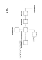
- FIG. 1 a circuit arrangement is shown as an exemplary embodiment.
- the measuring arrangement receives at the input the signal level of an FM coder, which is connected on the input side with the studio output signals. This value is converted to a sequence of level-representative numerical values at an appropriate sampling rate via an A / D converter. To these values, further shares of known multiplex signal components can be added, the level contributions are constant, if the feed is not done in the studio (eg RDS coder).
- the arithmetic mean is formed with respect to a fixed time interval (e.g., 60s). Due to the relationship between the average level value and all frequency deviation values occurring in the time interval, an average frequency deviation can be calculated for the interval, which enables the determination of the frequency deviation.
Landscapes
- Engineering & Computer Science (AREA)
- Quality & Reliability (AREA)
- Computer Networks & Wireless Communication (AREA)
- Signal Processing (AREA)
- Transmitters (AREA)
- Radar Systems Or Details Thereof (AREA)
- Monitoring And Testing Of Transmission In General (AREA)
- Testing, Inspecting, Measuring Of Stereoscopic Televisions And Televisions (AREA)
Description
- Die Erfindung betrifft das Gebiet der Messung von Frequenzhub bzw. Modulationsleistung für frequenzmodulierte Sender.
- Nach dem Stand der Technik werden Frequenzhub bzw. Modulationsleistung bei FM-Sendern durch Messung des ausgesendeten HF-Signals ermittelt. Dabei wird der Frequenzhub durch Zählen der Periodendauer jeder einzelnen Schwingung des HF-Trägers bestimmt (siehe
DE 4321149 ). Ein anderes Verfahren basiert auf der Frequenzmessung am Ausgang des FM-Modulators (sieheDE 3126804 ). Dazu ist auch ein digitales Verfahren bekannt (sieheDE 19534262 ). Ferner ist ausDD 267 115 A1 - Zur Vermeidung möglicher Störungen anderer Sender in Gleich-oder Nachbarkanälen sind für den FM-Tonrundfunk Schutzabstandskurven vereinbart worden (siehe Empfehlung ITU-R BS.412). Sie beruhen auf einen maximal zulässigen Spitzenhub (±75 kHz) und die über einen bestimmten Intervall (60s) gemittelte Modulationsleistung, die bei Modulation mit einem sinusförmigen Signal einen Frequenzhub von ±19 kHz verursacht.
- Die bekannten Verfahren zur Bestimmung von Frequenzhub bzw. Modulationsleistung haben den Nachteil, daß Überschreitungen der Grenzwerte erst im nachhinein durch Messung am Frequenzmodulator bzw. des ausgestrahlten und mit einem Meßempfänger empfangenen Sendesignals ermittelt werden.
- Das mit dieser Erfindung vorgelegte Verfahren geht davon aus, daß die Beziehung zwischen Modulationssignal und dem Frequenzhub des FM-Modulators für eine Einflußnahme auf die Parameter vor Ausstrahlung des modulierten HF-Trägersignals genutzt wird. Die Einhaltung der Grenzwerte für Frequenzhub/Modulationsleistung kann somit direkt am Studioausgang und damit durch den Programmanbieter selbst beurteilt werden. Überschreitungen der Grenzwerte sind von vornherein vermeidbar und Kosten können eingespart werden.
- Die Amplitude und die Frequenz des Studioausgangssignals (Multiplexsignal) stehen in direktem Zusammenhang mit dem vom FM-Modulator des Senders erzeugten Frequenzhub Δf (t). Wird mit einem sinusförmigen Signal moduliert, ist - bei konstanter Amplitude - jeder Frequenz ein definierter Frequenzhub zuzuordnen. Bei der Modulation mit einem Frequenzgemisch aus überlagerten nichtharmonischen Anteilen, wie es das Studioausgangssignal darstellt, trifft das Superpositionsgesetz nicht zu. Es ist also nicht möglich, aus dem FM-Spektrum bei sinusförmiger Modulation auf die Spektren bei beliebigen Modulationssignalen zu schließen. Daher wird ein "normiertes" Verfahren angewendet, das für die Praxis hinreichend genaue Ergebnisse liefert.
- Zwischen dem Signalpegel u(t) des Modulationssignals (Multiplexsignal) und dem Frequenzhub Δf(t) des FM-Modulators gilt folgende normierte Beziehung (siehe Richtlinie 176 TR 28):

- Dabei ist U0 der Signalpegel, der zu einem Frequenzhub von 40 kHz führt.
- Der lineare Zusammenhang zwischen der Modulationsspannung und dem Frequenzhub wird dazu verwendet, um durch eine Pegelmessung am Studioausgang den Frequenzhub des FM-Modulators zu bestimmen.
- Das Modulationssignal am Studioausgang enthält alle Stereo-Informationen und auch den Pilotton. Am Senderstandort werden weitere Multiplexkomponenten wie Verkehrsfunk-, RDS-Signal und andere hinzugefügt. Da der Frequenzhub zu deren Pegelanteile ebenfalls proportional ist, können die Anteile additiv berücksichtigt werden.
- In
Figur 1 ist eine Schaltungsanordnung als Ausführungsbeispiel dargestellt. - Die Messanordnung nimmt am Eingang den Signalpegel eines FM-Coders auf, der eingangsseitig mit den Studioausgangssignalen beschaltet ist. Dieser Wert wird mit einer geeigneten Abtastrate über einen A/D-Wandler in eine Folge pegelrepräsentierender Zahlenwerte umgewandelt. Zu diesen Werten können weitere Anteile bekannter Multiplexsignalanteile addiert werden, deren Pegelbeiträge konstant sind, wenn die Einspeisung nicht im Studio erfolgt (z.B. RDS-Coder).
- Aus der Folge umgewandelter Pegelwerte wird, bezogen auf ein festgelegtes Zeitintervall (z.B. 60s) der arithmetische Mittelwert gebildet. Aufgrund des Zusammenhangs zwischen mittlerem Pegelwert und allen im Zeitintervall aufgetretenen Frequenzhubwerten kann für das Intervall ein mittlerer Frequenzhub errechnet werden, der die Frequenzhubbestimmung ermöglicht.
Claims (2)
- Verfahren zur Messung der Aussteuerung von frequenzmodulierten Sendern, bei denen die Abhängigkeit zwischen dem vom Frequenzmodulator des Senders erzeugten Frequenzhub von den Parametern der zugeführten Modulationsspannung für die Bestimmung des Frequenzhubs des Senders genutzt wird,
dadurch gekennzeichnet,
dass am Studioausgang der Signalpegel der Modulationsspannung gemessen und eingestellt wird,
dass mit der Einstellung der Modulationsspannung am Studioausgang der Frequenzhub des Senders vor dem Modulationsvorgang festgelegt wird und
dass durch eine stetige Messung der Modulationsspannung am Studioausgang der Frequenzhub des Senders überwacht werden kann, so dass Frequenzhubüberschreitungen nicht auftreten können. - Verfahren nach Anspruch 1, dadurch gekennzeichnet, dass der lineare Zusammenhang zwischen dem Signalpegel der Modulationsspannung am Studioausgang und dem Frequenzhub des Senders durch eine normierte Beziehung, bezogen auf das Verhältnis eines Frequenzhubs von 40 kHz zu der für diesen Frequenzhub erforderlichen Modulationsspannung, dargestellt werden kann und dass die normierte Beziehung für die Einstellung und Überwachung des Frequenzhubs des Senders hinreichende Ergebnisse liefert.
Applications Claiming Priority (2)
| Application Number | Priority Date | Filing Date | Title |
|---|---|---|---|
| DE19944900 | 1999-09-10 | ||
| DE19944900A DE19944900A1 (de) | 1999-09-10 | 1999-09-10 | Verfahren zur Messung der Aussteuerung von frequenzmodulierten Sendern |
Publications (3)
| Publication Number | Publication Date |
|---|---|
| EP1083433A2 EP1083433A2 (de) | 2001-03-14 |
| EP1083433A3 EP1083433A3 (de) | 2001-10-04 |
| EP1083433B1 true EP1083433B1 (de) | 2009-05-06 |
Family
ID=7922569
Family Applications (1)
| Application Number | Title | Priority Date | Filing Date |
|---|---|---|---|
| EP00116071A Expired - Lifetime EP1083433B1 (de) | 1999-09-10 | 2000-07-27 | Verfahren zur Messung der Aussteuerung von Frequenzmodulierten Sendern |
Country Status (3)
| Country | Link |
|---|---|
| EP (1) | EP1083433B1 (de) |
| AT (1) | ATE430942T1 (de) |
| DE (2) | DE19944900A1 (de) |
Families Citing this family (1)
| Publication number | Priority date | Publication date | Assignee | Title |
|---|---|---|---|---|
| RU2248000C2 (ru) * | 2003-05-05 | 2005-03-10 | Поздняков Владислав Александрович | Цифровой измеритель модуляции |
Family Cites Families (12)
| Publication number | Priority date | Publication date | Assignee | Title |
|---|---|---|---|---|
| US2276672A (en) * | 1940-10-26 | 1942-03-17 | Rca Corp | Frequency modulation indicator |
| US2496259A (en) * | 1946-11-21 | 1950-02-07 | Standard Telephones Cables Ltd | Monitoring circuit |
| US2683253A (en) * | 1949-07-28 | 1954-07-06 | Fr Sadir Carpentier Soc | Modulation controlling device |
| GB955555A (en) * | 1961-02-10 | 1964-04-15 | Varian Associates | Frequency modulation measurement |
| CH401172A (de) * | 1961-03-07 | 1965-10-31 | Varian Associates | Apparat zum Messen des äquivalenten Frequenzhubes eines im Ausgangskreis eines Hochfrequenzgenerators durch Störgeräusche bedingten Frequenzmodulationsseitenbandes innerhalb eines wählbaren Frequenzbereiches |
| NO122136B (de) * | 1965-03-16 | 1971-05-24 | Ericsson Telefon Ab L M | |
| DE2147532C3 (de) * | 1971-09-20 | 1978-03-16 | Treumann Geb. Lewin, Yvonne, 1000 Berlin | Verfahren zur Bestimmung der Umhüllenden und Modulationstiefe wechselnder Signalgrößen |
| DE3126804C2 (de) | 1981-07-07 | 1984-08-09 | Siemens AG, 1000 Berlin und 8000 München | Prüfgerät für Frequenzmessungen an Frequenzmodulatoren |
| DD267115A1 (de) * | 1987-12-23 | 1989-04-19 | Post Rundfunk Fernsehtech | Frequenzhubmesser mit automatischer eichung |
| DE4321149C1 (de) | 1993-06-25 | 1995-02-02 | Rundfunk Betriebstechnik Gmbh | Verfahren zum Ermitteln von Kenngrößen der Aussteuerung eines FM-modulierten HF-Trägers |
| DE19549600C2 (de) * | 1994-09-19 | 1999-09-16 | Advantest Corp | Verfahren und Vorrichtung zur Messung des Frequenzhubs eines FM-Eingangssignals |
| DE19534262C2 (de) | 1994-09-19 | 1999-09-02 | Advantest Corp | Verfahren und Vorrichtung zur Messung des Frequenzbereichs eines FM-Signals |
-
1999
- 1999-09-10 DE DE19944900A patent/DE19944900A1/de not_active Withdrawn
-
2000
- 2000-07-27 DE DE50015638T patent/DE50015638D1/de not_active Expired - Lifetime
- 2000-07-27 AT AT00116071T patent/ATE430942T1/de not_active IP Right Cessation
- 2000-07-27 EP EP00116071A patent/EP1083433B1/de not_active Expired - Lifetime
Also Published As
| Publication number | Publication date |
|---|---|
| EP1083433A3 (de) | 2001-10-04 |
| DE50015638D1 (de) | 2009-06-18 |
| EP1083433A2 (de) | 2001-03-14 |
| DE19944900A1 (de) | 2001-03-15 |
| ATE430942T1 (de) | 2009-05-15 |
Similar Documents
| Publication | Publication Date | Title |
|---|---|---|
| DE4334079C2 (de) | Hochgenauer Radar-Entfernungsmesser | |
| EP0535196A1 (de) | Verfahren und anordnung zur abstandsmessung nach dem rückstrahlprinzip radar. | |
| EP0262461B1 (de) | Ultraschall-Strömungsgeschwindigkeitsmesser nach dem Phasendifferenz-Verfahren | |
| DE69823609T2 (de) | Überwachung der optischen Signalleistung mit einem Signaturbitmuster in WDM Systemen | |
| DE1256902B (de) | Auf dem Prinzip einer Messung der Laufzeit kohaerenter elektromagnetischer Schwingungen beruhende Vorrichtung zur Messung des Abstandes zweier voneinander entfernter Punkte | |
| DE2229339B2 (de) | Zur Fein- und Grobmessung umschaltender elektrooptischer Entfernungsmesser | |
| DE1935205A1 (de) | Schaltungsanordnung zum Messen der Nichtlinearitaet eines Nachrichtenuebertragungssystem | |
| DE19958206C2 (de) | Sendevorrichtung | |
| EP1083433A2 (de) | Verfahren zur Messung der Aussteuerung von Frequenzmodulierten Sendern | |
| EP1733196A1 (de) | Anordnung zur drehmomentmessung von rotierenden maschinenteilen | |
| DE19713967A1 (de) | Vorrichtung zur Abstandsmessung | |
| EP0218126B1 (de) | Verfahren zur Messung von Strömungsgeschwindigkeiten mit Ultraschallschwingungen | |
| EP0667536A2 (de) | Verfahren zum Testen einer FM-CW-Radaranlage und Anordnung zur Durchführung des Verfahrens | |
| DE2945172A1 (de) | Verfahren und geraet zur bestimmung der konzentration eines gases in einem gasgemisch, insbesondere des kohlendioxidgehaltes | |
| DE3532705C1 (de) | Optisches Messverfahren fuer Glasfaser-Strecken | |
| WO2005031377A1 (de) | Verfahren zum bestimmen des frequenzgangs eines elektrooptischen bauelements | |
| DE3841585C2 (de) | ||
| EP0025477A2 (de) | Verfahren und Anordnung zur Messung des Jitters von Taktsignalen in digitalen Übertragungssystemen | |
| EP1516427B1 (de) | Schaltungsanordnung mit phasenregelkreis und sendeempfänger mit der schaltungsanordnung | |
| DE1516253C3 (de) | Verfahren und Schaltungsanordnung zur Messung der Phasenverzerrungen eines elektrischen Vierpols, insbesondere Übertragungssystems | |
| DE2042163A1 (de) | Verfahren und Schaltungsanordnung zur Bestimmung der Phasenverschiebung zwischen zwei von einer einzigen Quelle stammenden Signalen der gleichen Frequenz | |
| DE102019115729A1 (de) | Fahrerassistenzsystem für ein Fahrzeug zur Bestimmung einer relativen Geschwindigkeit anhand einer Signalform eines Sendesignals | |
| DE2708093C2 (de) | Verfahren zum Messen des AM-PM-Umwandlungsf aktors an einem System mit frequenzmoduliertem Trägersignal und Schaltungsanordnung zur Durchführung des Verfahrens | |
| DE4236386C1 (de) | Verfahren zum Überwachen eines FM-Senders | |
| DE19534262C2 (de) | Verfahren und Vorrichtung zur Messung des Frequenzbereichs eines FM-Signals |
Legal Events
| Date | Code | Title | Description |
|---|---|---|---|
| PUAI | Public reference made under article 153(3) epc to a published international application that has entered the european phase |
Free format text: ORIGINAL CODE: 0009012 |
|
| AK | Designated contracting states |
Kind code of ref document: A2 Designated state(s): AT BE CH CY DE DK ES FI FR GB GR IE IT LI LU MC NL PT SE |
|
| AX | Request for extension of the european patent |
Free format text: AL;LT;LV;MK;RO;SI |
|
| PUAL | Search report despatched |
Free format text: ORIGINAL CODE: 0009013 |
|
| AK | Designated contracting states |
Kind code of ref document: A3 Designated state(s): AT BE CH CY DE DK ES FI FR GB GR IE IT LI LU MC NL PT SE |
|
| AX | Request for extension of the european patent |
Free format text: AL;LT;LV;MK;RO;SI |
|
| 17P | Request for examination filed |
Effective date: 20020404 |
|
| AKX | Designation fees paid |
Free format text: AT BE CH CY DE DK ES FI FR GB GR IE IT LI LU MC NL PT SE |
|
| 17Q | First examination report despatched |
Effective date: 20080711 |
|
| GRAP | Despatch of communication of intention to grant a patent |
Free format text: ORIGINAL CODE: EPIDOSNIGR1 |
|
| GRAS | Grant fee paid |
Free format text: ORIGINAL CODE: EPIDOSNIGR3 |
|
| GRAA | (expected) grant |
Free format text: ORIGINAL CODE: 0009210 |
|
| AK | Designated contracting states |
Kind code of ref document: B1 Designated state(s): AT BE CH CY DE DK ES FI FR GB GR IE IT LI LU MC NL PT SE |
|
| REG | Reference to a national code |
Ref country code: GB Ref legal event code: FG4D Free format text: NOT ENGLISH |
|
| REG | Reference to a national code |
Ref country code: CH Ref legal event code: EP |
|
| REG | Reference to a national code |
Ref country code: IE Ref legal event code: FG4D |
|
| REF | Corresponds to: |
Ref document number: 50015638 Country of ref document: DE Date of ref document: 20090618 Kind code of ref document: P |
|
| PG25 | Lapsed in a contracting state [announced via postgrant information from national office to epo] |
Ref country code: ES Free format text: LAPSE BECAUSE OF FAILURE TO SUBMIT A TRANSLATION OF THE DESCRIPTION OR TO PAY THE FEE WITHIN THE PRESCRIBED TIME-LIMIT Effective date: 20090817 Ref country code: PT Free format text: LAPSE BECAUSE OF FAILURE TO SUBMIT A TRANSLATION OF THE DESCRIPTION OR TO PAY THE FEE WITHIN THE PRESCRIBED TIME-LIMIT Effective date: 20090906 Ref country code: FI Free format text: LAPSE BECAUSE OF FAILURE TO SUBMIT A TRANSLATION OF THE DESCRIPTION OR TO PAY THE FEE WITHIN THE PRESCRIBED TIME-LIMIT Effective date: 20090506 |
|
| NLV1 | Nl: lapsed or annulled due to failure to fulfill the requirements of art. 29p and 29m of the patents act | ||
| PG25 | Lapsed in a contracting state [announced via postgrant information from national office to epo] |
Ref country code: NL Free format text: LAPSE BECAUSE OF FAILURE TO SUBMIT A TRANSLATION OF THE DESCRIPTION OR TO PAY THE FEE WITHIN THE PRESCRIBED TIME-LIMIT Effective date: 20090506 Ref country code: SE Free format text: LAPSE BECAUSE OF FAILURE TO SUBMIT A TRANSLATION OF THE DESCRIPTION OR TO PAY THE FEE WITHIN THE PRESCRIBED TIME-LIMIT Effective date: 20090806 |
|
| REG | Reference to a national code |
Ref country code: IE Ref legal event code: FD4D |
|
| PG25 | Lapsed in a contracting state [announced via postgrant information from national office to epo] |
Ref country code: DK Free format text: LAPSE BECAUSE OF FAILURE TO SUBMIT A TRANSLATION OF THE DESCRIPTION OR TO PAY THE FEE WITHIN THE PRESCRIBED TIME-LIMIT Effective date: 20090506 Ref country code: IE Free format text: LAPSE BECAUSE OF FAILURE TO SUBMIT A TRANSLATION OF THE DESCRIPTION OR TO PAY THE FEE WITHIN THE PRESCRIBED TIME-LIMIT Effective date: 20090506 |
|
| BERE | Be: lapsed |
Owner name: DEUTSCHE TELEKOM A.G. Effective date: 20090731 |
|
| PG25 | Lapsed in a contracting state [announced via postgrant information from national office to epo] |
Ref country code: MC Free format text: LAPSE BECAUSE OF NON-PAYMENT OF DUE FEES Effective date: 20090731 |
|
| PLBE | No opposition filed within time limit |
Free format text: ORIGINAL CODE: 0009261 |
|
| STAA | Information on the status of an ep patent application or granted ep patent |
Free format text: STATUS: NO OPPOSITION FILED WITHIN TIME LIMIT |
|
| 26N | No opposition filed |
Effective date: 20100209 |
|
| PG25 | Lapsed in a contracting state [announced via postgrant information from national office to epo] |
Ref country code: BE Free format text: LAPSE BECAUSE OF NON-PAYMENT OF DUE FEES Effective date: 20090731 |
|
| PG25 | Lapsed in a contracting state [announced via postgrant information from national office to epo] |
Ref country code: GR Free format text: LAPSE BECAUSE OF FAILURE TO SUBMIT A TRANSLATION OF THE DESCRIPTION OR TO PAY THE FEE WITHIN THE PRESCRIBED TIME-LIMIT Effective date: 20090807 |
|
| PGFP | Annual fee paid to national office [announced via postgrant information from national office to epo] |
Ref country code: CH Payment date: 20100726 Year of fee payment: 11 |
|
| PGFP | Annual fee paid to national office [announced via postgrant information from national office to epo] |
Ref country code: FR Payment date: 20100802 Year of fee payment: 11 Ref country code: AT Payment date: 20100721 Year of fee payment: 11 |
|
| PGFP | Annual fee paid to national office [announced via postgrant information from national office to epo] |
Ref country code: GB Payment date: 20100726 Year of fee payment: 11 |
|
| PGFP | Annual fee paid to national office [announced via postgrant information from national office to epo] |
Ref country code: DE Payment date: 20100922 Year of fee payment: 11 |
|
| PG25 | Lapsed in a contracting state [announced via postgrant information from national office to epo] |
Ref country code: IT Free format text: LAPSE BECAUSE OF FAILURE TO SUBMIT A TRANSLATION OF THE DESCRIPTION OR TO PAY THE FEE WITHIN THE PRESCRIBED TIME-LIMIT Effective date: 20090506 |
|
| PG25 | Lapsed in a contracting state [announced via postgrant information from national office to epo] |
Ref country code: LU Free format text: LAPSE BECAUSE OF NON-PAYMENT OF DUE FEES Effective date: 20090727 |
|
| PG25 | Lapsed in a contracting state [announced via postgrant information from national office to epo] |
Ref country code: CY Free format text: LAPSE BECAUSE OF FAILURE TO SUBMIT A TRANSLATION OF THE DESCRIPTION OR TO PAY THE FEE WITHIN THE PRESCRIBED TIME-LIMIT Effective date: 20090506 |
|
| REG | Reference to a national code |
Ref country code: CH Ref legal event code: PL |
|
| GBPC | Gb: european patent ceased through non-payment of renewal fee |
Effective date: 20110727 |
|
| REG | Reference to a national code |
Ref country code: AT Ref legal event code: MM01 Ref document number: 430942 Country of ref document: AT Kind code of ref document: T Effective date: 20110727 |
|
| REG | Reference to a national code |
Ref country code: FR Ref legal event code: ST Effective date: 20120330 |
|
| PG25 | Lapsed in a contracting state [announced via postgrant information from national office to epo] |
Ref country code: LI Free format text: LAPSE BECAUSE OF NON-PAYMENT OF DUE FEES Effective date: 20110731 Ref country code: CH Free format text: LAPSE BECAUSE OF NON-PAYMENT OF DUE FEES Effective date: 20110731 Ref country code: FR Free format text: LAPSE BECAUSE OF NON-PAYMENT OF DUE FEES Effective date: 20110801 Ref country code: DE Free format text: LAPSE BECAUSE OF NON-PAYMENT OF DUE FEES Effective date: 20120201 |
|
| REG | Reference to a national code |
Ref country code: DE Ref legal event code: R119 Ref document number: 50015638 Country of ref document: DE Effective date: 20120201 |
|
| PG25 | Lapsed in a contracting state [announced via postgrant information from national office to epo] |
Ref country code: GB Free format text: LAPSE BECAUSE OF NON-PAYMENT OF DUE FEES Effective date: 20110727 |
|
| PG25 | Lapsed in a contracting state [announced via postgrant information from national office to epo] |
Ref country code: AT Free format text: LAPSE BECAUSE OF NON-PAYMENT OF DUE FEES Effective date: 20110727 |