EP1083301B1 - High-efficiency power generating method - Google Patents
High-efficiency power generating method Download PDFInfo
- Publication number
- EP1083301B1 EP1083301B1 EP00402431A EP00402431A EP1083301B1 EP 1083301 B1 EP1083301 B1 EP 1083301B1 EP 00402431 A EP00402431 A EP 00402431A EP 00402431 A EP00402431 A EP 00402431A EP 1083301 B1 EP1083301 B1 EP 1083301B1
- Authority
- EP
- European Patent Office
- Prior art keywords
- heavy oil
- oil
- power generating
- crude oil
- steam
- Prior art date
- Legal status (The legal status is an assumption and is not a legal conclusion. Google has not performed a legal analysis and makes no representation as to the accuracy of the status listed.)
- Expired - Lifetime
Links
Images


Classifications
-
- F—MECHANICAL ENGINEERING; LIGHTING; HEATING; WEAPONS; BLASTING
- F01—MACHINES OR ENGINES IN GENERAL; ENGINE PLANTS IN GENERAL; STEAM ENGINES
- F01K—STEAM ENGINE PLANTS; STEAM ACCUMULATORS; ENGINE PLANTS NOT OTHERWISE PROVIDED FOR; ENGINES USING SPECIAL WORKING FLUIDS OR CYCLES
- F01K23/00—Plants characterised by more than one engine delivering power external to the plant, the engines being driven by different fluids
- F01K23/02—Plants characterised by more than one engine delivering power external to the plant, the engines being driven by different fluids the engine cycles being thermally coupled
- F01K23/06—Plants characterised by more than one engine delivering power external to the plant, the engines being driven by different fluids the engine cycles being thermally coupled combustion heat from one cycle heating the fluid in another cycle
- F01K23/10—Plants characterised by more than one engine delivering power external to the plant, the engines being driven by different fluids the engine cycles being thermally coupled combustion heat from one cycle heating the fluid in another cycle with exhaust fluid of one cycle heating the fluid in another cycle
- F01K23/103—Plants characterised by more than one engine delivering power external to the plant, the engines being driven by different fluids the engine cycles being thermally coupled combustion heat from one cycle heating the fluid in another cycle with exhaust fluid of one cycle heating the fluid in another cycle with afterburner in exhaust boiler
-
- Y—GENERAL TAGGING OF NEW TECHNOLOGICAL DEVELOPMENTS; GENERAL TAGGING OF CROSS-SECTIONAL TECHNOLOGIES SPANNING OVER SEVERAL SECTIONS OF THE IPC; TECHNICAL SUBJECTS COVERED BY FORMER USPC CROSS-REFERENCE ART COLLECTIONS [XRACs] AND DIGESTS
- Y02—TECHNOLOGIES OR APPLICATIONS FOR MITIGATION OR ADAPTATION AGAINST CLIMATE CHANGE
- Y02E—REDUCTION OF GREENHOUSE GAS [GHG] EMISSIONS, RELATED TO ENERGY GENERATION, TRANSMISSION OR DISTRIBUTION
- Y02E20/00—Combustion technologies with mitigation potential
- Y02E20/16—Combined cycle power plant [CCPP], or combined cycle gas turbine [CCGT]
Definitions
- the present invention relates to a high-efficiency power generating method.
- a light oil fraction (low boiling point component) obtained by fractional distillation is sent to a gas turbine, and is burned therein, by which electric power is generated.
- High-temperature combustion exhaust gas obtained by the gas turbine is sent to a boiler in place of air, a heavy oil fraction (high boiling point component) is burned in the boiler, and a steam turbine is rotated by high-temperature, high-pressure steam produced in the boiler, by which electric power is generated. That is to say, a method is provided in which electric power is generated while what is called repowering, in which exhaust gas of a gas turbine is charged into a boiler and is re-burned, is performed.
- atmospheric distillation has generally been used, in which crude oil or heavy oil is distilled by being heated to about 360°C.
- a heating furnace has been used to obtain the above-described heating temperature.
- the heating furnace generally burns fuel to obtain thermal energy, and heats stock oil by radiation heat generated during burning and by convection of coanbustion gas.
- the present invention has been made in view of the above situation, and accordingly an object thereof is to provide a high-efficiency power generating method in which a heating furnace is disused, so that a problem of heat loss of exhaust gas is solved, and no load for treatment of Sox and NOx in exhaust gas is added to a power generating system, whereby the power generating efficiency of an exhaust gas re-combustion system is further enhanced as a whole.
- the present invention provides a high-efficiency power generating method to generate electric power by an exhaust gas recombustion system using at least a gas turbine, a boiler, and a steam turbine, comprising the steps of heating crude oil or heavy oil with steam obtained from the boiler; distilling the crude oil or heavy oil under reduced pressure; and generating electric power by using an obtained light oil fraction as a gas turbine fuel and by using a heavy oil fraction as a boiler fuel.
- the crude oil or heavy oil can be heated easily by providing means for effecting heat exchange between the crude oil or heavy oil and the light oil fraction and/or heavy oil fraction obtained in a distillation column.
- a steam ejector can be used as means for reducing the pressure for vacuum distillation.
- the present invention provides a high-efficiency power generating method in which a heating furnace is disused, so that a problem of heat loss of exhaust gas is solved, and no load for treatment of SOx and NOx in exhaust gas is added to a power generating system, whereby the power generating efficiency of an exhaust gas re-combustion system is further enhanced as a whole.
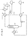
- FIG. 1 is a schematic view showing the outline of one embodiment of a system for separating crude oil or heavy oil by distillation, of systems for carrying out a high-efficiency power generating method in accordance with the present invention by using an exhaust gas recombustion system.
- a distillation apparatus in accordance with this embodiment includes a heater 1, a vacuum distillation column 2, and a steam ejector 3.
- the heater 1 which is means for heating crude oil or heavy oil, heats crude oil or heavy oil by heat exchange between steam and crude oil or heavy oil.
- the steam is supplied from a boiler (not shown).
- the steam obtained from the boiler is sent to a steam turbine to rotate the same, by which electric power is generated.
- the steam supplied to the heater 1 is one that has once rotated the steam turbine to generate electric power.
- the steam having a temperature of about 600°C is supplied to the steam turbine, and after power generation, the pressure and temperature thereof turn to about 20 kg/cm 2 G and about 200 to 230°C, respectively.
- the heater 1 is supplied with the steam having a pressure of about 20 kg/cm 2 G and a temperature of about 200 to 230°C.
- the vacuum distillation column 2 is an apparatus for distilling crude oil or heavy oil under reduced pressure.
- the vacuum distillation column 2 is generally provided with a multi-tier tray, and a light oil fraction and a heavy oil fraction accumulate at the upper and lower parts thereof, respectively.
- the steam ejector 3 which is an apparatus for reducing the pressure in the vacuum distillation column 2, sucks gas in the distillation column by causing steam to flow at a high flow velocity, so that the pressure in the vacuum distillation column 2 is reduced to a value lower than the atmospheric pressure.
- Crude oil or heavy oil supplied as a fuel to a power station passes through the heater 1 through a supply line L1, and is supplied to the vacuum distillation column 2.
- the heater 1 is supplied with steam that has once rotated the steam turbine to generate electric power.
- This steam having a pressure of about 20 kg/cm 2 G and a temperature of about 200 to 230°C, heats the crude oil or heavy oil flowing in the heater 1 to a temperature of about 200°C.
- the interior of the vacuuin distillation column 2 is decompressed by the sucking operation of the steam ejector 3.
- the vacuum distillation column 2 having a reduced pressure (50 mmHg) the crude oil or heavy oil is distilled, and the light oil fraction evaporates efficiently even at the temperature of about 200°C.
- the light oil fraction and the heavy oil fraction are separated to the upper and lower parts of the vacuum distillation column 2, respectively.
- the components such as sodium, vanadium, and potassium do not evaporate, so that they do not intrude into the light oil fraction. Therefore, the light oil fraction can provide a good-quality gas turbine fuel.
- the light oil fraction is transferred to a separation tank 4 in such a mamer as to be sucked by the steam ejector 3, and is separated into a gas component and a liquid component in the separation tank 4.
- the liquid component which is the light oil fraction, is sucked from the bottom portion of the separation tank 4 by a pump 7. Some thereof recirculates to the upper part of the vacuum distillation column 2, and the remainder thereof is stored in a storage tank 5.
- the gas component is taken out from the upper part of the separation tank 4.
- the light oil fraction is subjected to heat exchange with the crude oil or heavy oil by using a heat exchanger 6 during the time when it is sucked by the steam ejector 3, by which the crude oil or heavy oil is heated.
- the heavy oil fraction sucked from the bottom portion of the vacuum distillation column 2 by a pump 8 is stored in a heavy oil fraction storage tank 10.
- the heavy oil fraction sucked by the pump 8 passes through a heat exchanger 9 on the way to the storage tank 10, so that heat exchange with the crude oil or heavy oil is effected, by which the oil is heated.
- the light oil fraction and the heavy oil fraction stored in the storage tanks 5 and 10, respectively, are taken out as necessary for the use as fuel.
- the light oil fraction and the heavy oil fraction can be sent directly to a later-stage power generating process without passing through the storage tank.
- the light oil fraction is used as a gas turbine fuel
- the heavy oil fraction is used as a boiler fuel.
- the burning of boiler fuel using the combustion exhaust gas of the gas turbine in which about 13 vol% or more of oxygen remains does not cause special hindrance to the combustion in the boiler. Since high-temperature thermal energy of about 580°C that the combustion exhaust gas of the gas turbine has can be used effectively in the boiler, the fuel for the boiler can be saved.
- the amount of power generation can be increased as a whole, and the power generating efficiency per fuel can also be improved. That is to say, repowering can be performed.
- the power generating method in accordance with this embodiment steam that is originally present in the power station is used effectively, and also there are not problems of heat loss of exhaust gas and addition of a load for treatment of SOx and NOx in exhaust gas because no heating furnace is used. That is to say, the power generating efficiency of the exhaust gas re-combustion system is further enhanced as a whole.
- the vacuum distillation column 2 has a reduced pressure of 50mmHg.
- this reduced pressure may vary from 30mmHg to 500mmHg depending on the conditions.
Applications Claiming Priority (2)
| Application Number | Priority Date | Filing Date | Title |
|---|---|---|---|
| JP25424299 | 1999-09-08 | ||
| JP25424299A JP2001073715A (ja) | 1999-09-08 | 1999-09-08 | 高効率発電方法 |
Publications (3)
| Publication Number | Publication Date |
|---|---|
| EP1083301A2 EP1083301A2 (en) | 2001-03-14 |
| EP1083301A3 EP1083301A3 (en) | 2003-03-12 |
| EP1083301B1 true EP1083301B1 (en) | 2006-03-29 |
Family
ID=17262260
Family Applications (1)
| Application Number | Title | Priority Date | Filing Date |
|---|---|---|---|
| EP00402431A Expired - Lifetime EP1083301B1 (en) | 1999-09-08 | 2000-09-05 | High-efficiency power generating method |
Country Status (11)
| Country | Link |
|---|---|
| US (1) | US6381943B1 (ru) |
| EP (1) | EP1083301B1 (ru) |
| JP (1) | JP2001073715A (ru) |
| KR (1) | KR20010050334A (ru) |
| CN (1) | CN1194165C (ru) |
| AU (1) | AU764568C (ru) |
| CA (1) | CA2317681C (ru) |
| DE (1) | DE60026957T2 (ru) |
| ES (1) | ES2257273T3 (ru) |
| ID (1) | ID27142A (ru) |
| RU (1) | RU2198310C2 (ru) |
Families Citing this family (10)
| Publication number | Priority date | Publication date | Assignee | Title |
|---|---|---|---|---|
| JP4637691B2 (ja) * | 2005-09-06 | 2011-02-23 | 中国電力株式会社 | 発電用ボイラの燃料加熱システムおよび燃料の加熱方法 |
| GB0612014D0 (en) * | 2006-06-16 | 2006-07-26 | Quadrise Ltd | Method |
| US8021537B2 (en) * | 2006-10-24 | 2011-09-20 | Acs Engineering Technologies, Inc. | Steam generation apparatus and method |
| JP2009228475A (ja) * | 2008-03-19 | 2009-10-08 | Mitsubishi Heavy Ind Ltd | ガスタービン発電システム |
| JP5232923B2 (ja) * | 2009-12-18 | 2013-07-10 | 三菱重工業株式会社 | ガスタービンコンバインドサイクル発電設備および方法 |
| JP4634538B1 (ja) | 2010-05-27 | 2011-02-23 | 住友商事株式会社 | ハイブリッド火力発電システム及びその建造方法 |
| US20130186097A1 (en) * | 2012-01-23 | 2013-07-25 | General Electric Company | Liquid Fuel Heating System |
| JP5781562B2 (ja) * | 2013-05-29 | 2015-09-24 | 三菱日立パワーシステムズ株式会社 | ガスタービン発電システム |
| JP5863875B2 (ja) * | 2014-05-09 | 2016-02-17 | 三菱日立パワーシステムズ株式会社 | ガスタービン発電システム |
| CN104560161A (zh) * | 2015-02-05 | 2015-04-29 | 中石化上海工程有限公司 | 裂解汽油加氢装置二段反应器入口物料加热方法 |
Family Cites Families (7)
| Publication number | Priority date | Publication date | Assignee | Title |
|---|---|---|---|---|
| GB1020667A (en) | 1964-02-21 | 1966-02-23 | British Petroleum Co | Improvements relating to petroleum distillation |
| DE3814242A1 (de) * | 1988-04-27 | 1989-11-09 | Siemens Ag | Dampfkraftwerk |
| JP2511227B2 (ja) * | 1992-10-02 | 1996-06-26 | 三菱重工業株式会社 | 発電燃料の製造方法と発電方法 |
| JP2599095B2 (ja) * | 1993-10-14 | 1997-04-09 | 中国電力株式会社 | 原油分留式コンバインドサイクル発電システム |
| JP3790297B2 (ja) | 1996-05-24 | 2006-06-28 | 三菱重工業株式会社 | 重質油焚き複合発電設備 |
| JP3706432B2 (ja) * | 1996-06-18 | 2005-10-12 | 三菱重工業株式会社 | コンバインド・サイクル発電設備 |
| JP4495791B2 (ja) * | 1998-07-03 | 2010-07-07 | 日揮株式会社 | コンバインドサイクル発電システム |
-
1999
- 1999-09-08 JP JP25424299A patent/JP2001073715A/ja active Pending
-
2000
- 2000-08-24 CN CNB001240323A patent/CN1194165C/zh not_active Expired - Fee Related
- 2000-08-28 US US09/649,220 patent/US6381943B1/en not_active Expired - Lifetime
- 2000-09-04 ID IDP20000750A patent/ID27142A/id unknown
- 2000-09-05 ES ES00402431T patent/ES2257273T3/es not_active Expired - Lifetime
- 2000-09-05 EP EP00402431A patent/EP1083301B1/en not_active Expired - Lifetime
- 2000-09-05 DE DE60026957T patent/DE60026957T2/de not_active Expired - Lifetime
- 2000-09-05 KR KR1020000052273A patent/KR20010050334A/ko active Search and Examination
- 2000-09-06 CA CA002317681A patent/CA2317681C/en not_active Expired - Fee Related
- 2000-09-07 AU AU56571/00A patent/AU764568C/en not_active Ceased
- 2000-09-07 RU RU2000123248/06A patent/RU2198310C2/ru not_active IP Right Cessation
Also Published As
| Publication number | Publication date |
|---|---|
| AU764568B2 (en) | 2003-08-21 |
| US6381943B1 (en) | 2002-05-07 |
| CN1287148A (zh) | 2001-03-14 |
| EP1083301A2 (en) | 2001-03-14 |
| CN1194165C (zh) | 2005-03-23 |
| KR20010050334A (ko) | 2001-06-15 |
| EP1083301A3 (en) | 2003-03-12 |
| CA2317681C (en) | 2006-05-09 |
| RU2198310C2 (ru) | 2003-02-10 |
| CA2317681A1 (en) | 2001-03-08 |
| AU5657100A (en) | 2001-03-22 |
| AU764568C (en) | 2004-07-01 |
| JP2001073715A (ja) | 2001-03-21 |
| ID27142A (id) | 2001-03-08 |
| DE60026957D1 (de) | 2006-05-18 |
| DE60026957T2 (de) | 2007-01-04 |
| ES2257273T3 (es) | 2006-08-01 |
Similar Documents
| Publication | Publication Date | Title |
|---|---|---|
| AU687519B2 (en) | Method and device for solar steam generation | |
| EP1083301B1 (en) | High-efficiency power generating method | |
| EP1391596B1 (en) | Gas turbine plant | |
| US7350471B2 (en) | Combustion system with recirculation of flue gas | |
| JP4030432B2 (ja) | ガスタービン発電装置 | |
| RU2485331C2 (ru) | Способ и устройство для преобразования тепловой энергии низкотемпературного источника тепла в механическую энергию | |
| RU2009333C1 (ru) | Комбинированная парогазовая энергетическая установка и способ ее эксплуатации | |
| US7493768B2 (en) | Method for increasing the efficiency of a gas turbine system and gas turbine system suitable therefor | |
| KR101422430B1 (ko) | 재가열 사이클을 갖는 하이브리드 바이오매스 처리 | |
| EP2264287A1 (en) | Energy generating method using thermal cycles with high-pressure and moderate-temperature steam | |
| CN101178017A (zh) | 钢铁厂余热锅炉饱和蒸汽回收再发电的方法 | |
| US11022005B2 (en) | Steam turbine power plant utilizing industrial heat pumps to preheat boiler feed-water | |
| KR20100047813A (ko) | 고체연료와 폐열로부터 가스 터빈을 이용한 발전 공정 및 이 공정을 수행하기 위한 장비 | |
| SU1521284A3 (ru) | Энергетическа установка | |
| US10753600B2 (en) | Turbine system and method | |
| US4896496A (en) | Single pressure steam bottoming cycle for gas turbines combined cycle | |
| EP3844371B1 (en) | System for generating energy in a working fluid from hydrogen and oxygen and method of operating this system | |
| RU2000123248A (ru) | Способ производства энергии с высоким коэффициентом полезного действия | |
| JP2000516315A (ja) | 機械的作業を達成して所望であれば蒸発性ガスタービン処理で熱を発生させる方法および装置 | |
| JPH102234A (ja) | コンバインド・サイクル発電設備 | |
| KR102164816B1 (ko) | 효율향상 및 열소비율 저감을 위한 발전 시스템 | |
| CN108977241A (zh) | 一种带co2捕集的燃煤发电系统及方法 | |
| JP2001115855A (ja) | ガスタービンシステム | |
| JPH05340205A (ja) | 複合発電プラントの制御装置 | |
| JPH09194852A (ja) | コンバインド・サイクル発電用燃料の製造方法 |
Legal Events
| Date | Code | Title | Description |
|---|---|---|---|
| PUAI | Public reference made under article 153(3) epc to a published international application that has entered the european phase |
Free format text: ORIGINAL CODE: 0009012 |
|
| AK | Designated contracting states |
Kind code of ref document: A2 Designated state(s): AT BE CH CY DE DK ES FI FR GB GR IE IT LI LU MC NL PT SE |
|
| AX | Request for extension of the european patent |
Free format text: AL;LT;LV;MK;RO;SI |
|
| RIN1 | Information on inventor provided before grant (corrected) |
Inventor name: KOBAYASHI, KAZUTO, MITSUBISHI HEAVY IND. LTD. Inventor name: IIJIMA, MASAKI, MITSUBISHI HEAVY INDUSTRIES, LTD. Inventor name: MORIWAKI, MASAYUKI, MITSUBISHI HEAVY IND. LTD. Inventor name: HYAKUTAKE, YOSHINORI MITSUBISHI HEAVY INDUSTRIES, Inventor name: HYAKUTAKE, YOSHINORI, MITSUBISHI HEAVY IND. LTD. |
|
| PUAL | Search report despatched |
Free format text: ORIGINAL CODE: 0009013 |
|
| AK | Designated contracting states |
Kind code of ref document: A3 Designated state(s): AT BE CH CY DE DK ES FI FR GB GR IE IT LI LU MC NL PT SE |
|
| AX | Request for extension of the european patent |
Extension state: AL LT LV MK RO SI |
|
| 17P | Request for examination filed |
Effective date: 20030423 |
|
| AKX | Designation fees paid |
Designated state(s): DE DK ES GB IT NL |
|
| GRAP | Despatch of communication of intention to grant a patent |
Free format text: ORIGINAL CODE: EPIDOSNIGR1 |
|
| GRAS | Grant fee paid |
Free format text: ORIGINAL CODE: EPIDOSNIGR3 |
|
| GRAA | (expected) grant |
Free format text: ORIGINAL CODE: 0009210 |
|
| AK | Designated contracting states |
Kind code of ref document: B1 Designated state(s): DE DK ES GB IT NL |
|
| PG25 | Lapsed in a contracting state [announced via postgrant information from national office to epo] |
Ref country code: NL Free format text: LAPSE BECAUSE OF FAILURE TO SUBMIT A TRANSLATION OF THE DESCRIPTION OR TO PAY THE FEE WITHIN THE PRESCRIBED TIME-LIMIT Effective date: 20060329 |
|
| REG | Reference to a national code |
Ref country code: GB Ref legal event code: FG4D |
|
| RIN1 | Information on inventor provided before grant (corrected) |
Inventor name: IIJIMA, MASAKI,MITSUBISHI HEAVY INDUSTRIES, LTD. Inventor name: MORIWAKI, MASAYUKI,MITSUBISHI HEAVY IND. LTD. Inventor name: KOBAYASHI, KAZUTO,MITSUBISHI HEAVY IND. LTD. Inventor name: HYAKUTAKE, YOSHINORI MITSUBISHI HEAVY INDUSTRIES, Inventor name: SHIBATA, MASATOSHI,MITSUBISHI HEAVY IND. LTD. |
|
| REF | Corresponds to: |
Ref document number: 60026957 Country of ref document: DE Date of ref document: 20060518 Kind code of ref document: P |
|
| PG25 | Lapsed in a contracting state [announced via postgrant information from national office to epo] |
Ref country code: DK Free format text: LAPSE BECAUSE OF FAILURE TO SUBMIT A TRANSLATION OF THE DESCRIPTION OR TO PAY THE FEE WITHIN THE PRESCRIBED TIME-LIMIT Effective date: 20060629 |
|
| REG | Reference to a national code |
Ref country code: ES Ref legal event code: FG2A Ref document number: 2257273 Country of ref document: ES Kind code of ref document: T3 |
|
| NLV1 | Nl: lapsed or annulled due to failure to fulfill the requirements of art. 29p and 29m of the patents act | ||
| PLBE | No opposition filed within time limit |
Free format text: ORIGINAL CODE: 0009261 |
|
| STAA | Information on the status of an ep patent application or granted ep patent |
Free format text: STATUS: NO OPPOSITION FILED WITHIN TIME LIMIT |
|
| 26N | No opposition filed |
Effective date: 20070102 |
|
| PGFP | Annual fee paid to national office [announced via postgrant information from national office to epo] |
Ref country code: DE Payment date: 20150902 Year of fee payment: 16 Ref country code: GB Payment date: 20150902 Year of fee payment: 16 Ref country code: ES Payment date: 20150810 Year of fee payment: 16 |
|
| PGFP | Annual fee paid to national office [announced via postgrant information from national office to epo] |
Ref country code: IT Payment date: 20150925 Year of fee payment: 16 |
|
| REG | Reference to a national code |
Ref country code: DE Ref legal event code: R119 Ref document number: 60026957 Country of ref document: DE |
|
| GBPC | Gb: european patent ceased through non-payment of renewal fee |
Effective date: 20160905 |
|
| PG25 | Lapsed in a contracting state [announced via postgrant information from national office to epo] |
Ref country code: DE Free format text: LAPSE BECAUSE OF NON-PAYMENT OF DUE FEES Effective date: 20170401 Ref country code: GB Free format text: LAPSE BECAUSE OF NON-PAYMENT OF DUE FEES Effective date: 20160905 |
|
| PG25 | Lapsed in a contracting state [announced via postgrant information from national office to epo] |
Ref country code: IT Free format text: LAPSE BECAUSE OF NON-PAYMENT OF DUE FEES Effective date: 20160905 |
|
| PG25 | Lapsed in a contracting state [announced via postgrant information from national office to epo] |
Ref country code: ES Free format text: LAPSE BECAUSE OF NON-PAYMENT OF DUE FEES Effective date: 20160906 |
|
| REG | Reference to a national code |
Ref country code: ES Ref legal event code: FD2A Effective date: 20181121 |