EP1081663B1 - Machine de vente avec un dispositif de délivrance d'articles excellent en sécurité anti-vol - Google Patents
Machine de vente avec un dispositif de délivrance d'articles excellent en sécurité anti-vol Download PDFInfo
- Publication number
- EP1081663B1 EP1081663B1 EP00307386A EP00307386A EP1081663B1 EP 1081663 B1 EP1081663 B1 EP 1081663B1 EP 00307386 A EP00307386 A EP 00307386A EP 00307386 A EP00307386 A EP 00307386A EP 1081663 B1 EP1081663 B1 EP 1081663B1
- Authority
- EP
- European Patent Office
- Prior art keywords
- commodity
- hook
- discharge apparatus
- endless chain
- commodity discharge
- Prior art date
- Legal status (The legal status is an assumption and is not a legal conclusion. Google has not performed a legal analysis and makes no representation as to the accuracy of the status listed.)
- Expired - Lifetime
Links
- 230000001737 promoting effect Effects 0.000 claims description 16
- 239000000725 suspension Substances 0.000 description 40
- 230000008878 coupling Effects 0.000 description 13
- 238000010168 coupling process Methods 0.000 description 13
- 238000005859 coupling reaction Methods 0.000 description 13
- 239000011435 rock Substances 0.000 description 1
Images
Classifications
-
- G—PHYSICS
- G07—CHECKING-DEVICES
- G07F—COIN-FREED OR LIKE APPARATUS
- G07F11/00—Coin-freed apparatus for dispensing, or the like, discrete articles
- G07F11/46—Coin-freed apparatus for dispensing, or the like, discrete articles from movable storage containers or supports
- G07F11/58—Coin-freed apparatus for dispensing, or the like, discrete articles from movable storage containers or supports the articles being supported on or by endless belts or like conveyors
Definitions
- the present invention relates to a commodity discharge apparatus for a vending machine.
- a conventional commodity discharge apparatus for a vending machine is disclosed in, for example, Japanese Unexamined Utility Model Publication (JP-U) No. S49-150300.
- the conventional commodity discharge apparatus comprises an endless chain supported on a pair of sprockets to extend therebetween in a horizontal direction, and a plurality of hooks unrotatably attached to a plurality of pins of the endless chain, respectively, and arranged at a predetermined interval from each other.
- Commodities or goods are hooked to the hooks and carried along the endless chain towards a predetermined position by movement of the endless chain. On arriving at the predetermined position, each of the commodities is fallen from each of the hooks in the manner known in the art.
- the commodities can easily be released from the hooks before arrival at the predetermined position as well known in the art. Accordingly, the conventional commodity discharge apparatus has a risk that the commodities may be stolen in the manner which will be described below. Specifically, a stealer can rock a whole of the vending machine comprising the above-mentioned commodity discharge apparatus so that one or ones of the commodities are released from respective hooks to fall down towards a commodity outlet or discharge port. Then, the stealer can take out the goods from the commodity outlet port.
- Claim 1 discloses the present invention. Preferred embodiments are disclosed in claims 2 - 9.
- a commodity discharge apparatus to which the present invention is applicable is for a vending machine.
- the commodity discharge apparatus comprises first and second sprockets spaced from each other in a horizontal direction and an endless chain engaged with the first and the second sprockets and extending on a vertical plane to form an endless loop.
- the endless chain is adapted to circulate through the first and the second sprockets and through a lower and an upper traveling path each extending between the first and the second sprockets.
- the commodity discharge apparatus further comprises a hook unrotatably attached to a part of the endless chain for hooking a commodity only when the part is placed at the lower traveling path and a fall preventing member extending in parallel to the lower traveling path beside the hook for preventing a fall of the commodity from the hook.
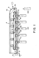
- the commodity discharge apparatus comprises a first or rear sprocket 1a, a second or front sprocket 1b spaced from the rear sprocket 1a in a horizontal direction, and an endless chain 2 supported on the rear and the front sprockets 1a and 1b to extend therebetween on a vertical plane.
- the rear sprocket 1a is connected to a motor (not shown) having an encoder for driving the rotation of the rear sprocket 1a.
- the endless chain 2 travels along upper and lower traveling paths to circulate around the rear and the front sprockets 1a and 1b. More particularly, the endless chain 2 adapted to circulate through the rear and the front sprockets 1a and 1b and through a lower and an upper traveling path each extending between the rear and the front sprockets 1a and 1b.
- a part of the endless chain 2 traveling along the upper traveling path may be referred to as an upper traveling portion.
- the other part traveling along the lower traveling path may be referred to as a lower traveling portion.
- the lower traveling portion of the endless chain 2 travels from the rear sprocket 1a toward the front sprocket 1b in a forward direction while the upper traveling portion travels from the front sprocket 1b toward the rear sprocket 1a in a rearward direction.
- the endless chain 2 carries a plurality of commodity suspension hooks 3 which are attached to the endless chain 2 at a predetermined interval from one another for hooking commodities or goods only in the lower traveling portion of the endless chain 2.
- the endless chain 2 is accommodated in a cylindrical casing 4 having a generally rectangular section.
- the casing 4 has a bottom wall 4a extending generally in parallel to the endless chain 2 at a position immediately below the endless chain 2.
- the bottom wall 4a has a gap 4b extending in a longitudinal direction.
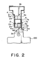
- the lower traveling portion of the endless chain 2 and the commodity suspension hook 3 in the suspended position are supported by the bottom wall 4a of the casing 4 in the vertical direction.
- the hook portion 3b of the commodity suspension hook 3 in the suspended position extends through the gap 4b to a position outside and below the casing 4.
- the commodity suspension hooks 3 can take a suspended position in which they are suspended from the lower traveling portion of the endless chain 2 and a standing position in which they stand up from the upper traveling portion of the endless chain 2.
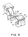
- the casing 4 has a front end in the vicinity of the front sprocket 1b.
- the front end is closed by a cover 5 having a curved top wall 5a and a side wall 5b having a generally U-shaped section.
- the casing 4 is provided with a guide rail 6 having a generally U-shaped section and arranged within the casing 4.
- the guide rail 6 extends generally in parallel to the endless chain 2.
- the upper traveling portion of the endless chain 2 and the commodity suspension hook 3 in the standing position are supported by the guide rail 6 in the vertical direction.
- the hook portion 3b of the commodity suspension hook 3 in the standing position is accommodated within the casing 4.
- the commodity discharge apparatus further comprises a fall preventing plate 7 for preventing commodities or goods undesiredly falling off from the commodity suspension hooks 3.
- the fall preventing plate 7 extends in parallel to the endless chain 2 on a lateral side of the hook portions 3b of the commodity suspension hooks 3 and at a level substantially equal to that of the free ends 3b' of the hook portions 3b of the commodity suspension hooks 3 in the suspended position.
- the fall preventing plate 7 extends over a substantially full length of the endless chain 2.
- the fall preventing plate 7 extends to its rear end in the vicinity of a rear end of the casing 4.
- the fall preventing plate 7 has a fitting portion 7a integrally formed therewith and is attached to one of side walls of the casing 4 via the fitting portion 7a.
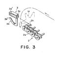
- the endless chain 2 is generally called a roller chain and comprises a plurality of roller links 2a and a plurality of coupling pins 2b connecting the roller links 2a to each other to form an endless loop.
- Each of the coupling pins 2b protrudes on one side of the endless chain 2 or the roller links 2 in the horizontal direction.
- Each of the commodity suspension hooks 3 comprises a coupling portion 3a and a hook portion 3b integrally formed with the coupling portion 3a.
- the coupling portion 3a is provided with a coupling hole 3a' of a generally elliptical shape.
- the coupling portion 3a of each commodity suspension hook 3 is tightly fitted over two adjacent ones of the coupling pins 2b of the endless chain 2 when the coupling pins 2b are inserted into the coupling hole 3a'.
- the commodity suspension hook 3 is attached to the endless chain 2 to be unrotatable around the coupling pins 2b.
- each of the commodity suspension hooks 3 is attached to the two coupling pins 2b of the lower traveling portion of the endless chain 2 in such a manner that a free end 3b' of the hook portion 3b is faced rearward.
- the hook portion 3b is so sharply bent that the free end 3b' of the hook portion 3b is closely adjacent to the coupling portion 3a.
- the fitting portion 7a of the fall preventing plate 7 has a pair of elongated holes 7b with a space left therebetween in the horizontal direction.
- Each of the elongated holes 7b has an intermediate portion 7b1 extending in the horizontal direction, an operation-mode locking portion 7b2 extending from a rear end of the intermediate portion 7b1 obliquely up rearward, and a retraction-mode locking portion 7b3 extending from a front end of the intermediate portion 7b1 obliquely up frontward.
- the operation-mode locking portion 7b2 has an upper end located above an upper end of the retraction-mode locking portion 7b3.
- the fall preventing plate 7 is attached to the one side wall of the casing 4 with the elongated holes 7b of the fitting portion 7a engaged with stepped screws 7c screwed into the one side wall of the casing 4.
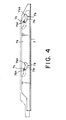
- the operation-mode locking portion 7b2 of the elongated hole 7b is engaged with the stepped screw 7c and, as illustrated by solid lines in Figs. 1, 2, and 4, the fall preventing plate 7 is located at an operating position which is a lower and forward position. In this event, the fall preventing plate 7 extends in parallel to the endless chain 2 at the level substantially equal to that of the free ends 3b' of the hook portions 3b of the commodity suspension hooks 3 in the suspended position.
- the retraction-mode locking portion 7b3 of each of the elongated holes 7b is engaged with the stepped screw 7c and, as illustrated by dot-and-dash lines in Figs. 1, 3, and 5, the fall preventing plate 7 is located at a retracted position which is an upper rearward position. In this event, the fall preventing plate 7 extends in parallel to the endless chain 2 at a level above the free ends 3b' of the hook portions 3b of the commodity suspension hooks 3 in the suspended position.
- the commodity discharge apparatus further comprises, as a release promoting member, a pair of release promoting plates 8a and 8b having an L-shaped plan view and interposed between the front end of the casing 4 and the cover 5.
- the release promoting plates 8a and 8b have edge portions 8a' and 8b', respectively, extending in the vertical direction.
- Each of the release promoting plates 8a and 8b is referred to as a release promoting member.
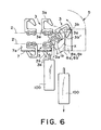
- the commodity suspension hook 3 moves around the front sprocket 1b when it is transferred from the lower traveling portion to the upper traveling portion of the endless chain 2.
- the free end 3b' of the hook portion 3b of the commodity suspension hook 3 follows a locus X.
- Each of the edge portions 8a' and 8b' is located in the vicinity of a farthest point on the locus X of the free end 3b' of the hook portion 3b.
- the farthest point is farthest from the front sprocket 1b in the horizontal direction among any other points on the locus X.
- the release promoting plates 8a and 8b are located on one lateral side and the other lateral side of the hook portion 3b of the commodity suspension hook 3 moving around the front sprocket 1b, respectively.
- the release promoting plates 8a and 8b are arranged so that the commodity suspension hook 3 moving around the front sprocket 1b is allowed to pass through without touching the release promoting plates 8a and 8b.
- a plurality of commodity discharge apparatuses having the above-described structure are equipped in the vending machine (not shown) in a layered arrangement at a predetermined interval from each other in the vertical direction.
- Each commodity discharge apparatus is supported by a suspending device (not shown) to be movable in the horizontal direction. If the commodity discharge apparatus at the operating position is pulled in the forward direction depicted by a white arrow in Fig. 1, the commodity discharge apparatus can be drawn out from the vending machine in the forward direction. Referring to Fig. 1, when the commodity discharge apparatus is located at the operating position, the rear end of the casing 4 of the commodity discharge apparatus is closely adjacent to a driving plate 9 attached to a casing (not shown) of the vending machine.
- the commodities 100 may be different in kind in the respective commodity discharge apparatuses.
- a purchaser or consumer throws the coin into a coin slot (not shown) of the vending machine and pushes a commodity selecting button (not shown).
- the motor with the encoder (not shown) is activated to rotate the rear sprocket 1a by a predetermined angle.
- the lower traveling portion of the endless chain 2 moves toward the front sprocket 1b over a predetermined distance.
- the commodity suspension hooks 3 suspended from the lower traveling portion of the endless chain 2 move toward the front sprocket 1b by the predetermined distance. While the commodity suspension hooks 3 in the suspended position move toward the front sprocket 1b, the weights of the endless chain 2, the commodity suspension hooks 3, and the commodities 100 are supported by the bottom wall 4a of the casing 4.
- the fall preventing plate 7 When the commodity discharge apparatus is put into operation, the fall preventing plate 7 is located at the operating position depicted by a solid line in each of Figs. 1 and 2. As described above, the fall preventing plate 7 extends in parallel to the endless chain 2 on the lateral side of the hook portions 3b of the commodity suspension hooks 3 and at the level substantially equal to that of the free ends 3b' of the hook portions 3b of the commodity suspension hooks 3 in the suspended position. As is apparent from Figs. 1 and 3, when the commodity suspension hooks 3 in the suspended position are seen from the lateral side, an opening of the hook portion 3b is closed by the fall preventing plate 7 mentioned above. With this structure, the commodities 100 will not easily be released from the hook portions 3b even if the vending machine is rocked. This is because an upper end of each commodity 100 is brought into contact with the fall preventing plate 7. Therefore, the commodity discharge apparatus is excellent in theftproofness.
- the commodity discharge apparatus In order to charge the commodities 100, i.e., in order to hook the commodities 100 on the commodity suspension hooks 3, the commodity discharge apparatus is pulled in the forward direction depicted by the white arrow in Fig. 1 to be drawn out from the vending machine. Then, the fall preventing plate 7 is pushed in the rearward direction to be moved to the retracted position depicted by a dot-dash line in each of Figs. 1 and 2. At the retracted position, the fall preventing plate 7 extends in parallel to the endless chain 2 above the free ends 3b' of the hook portions 3b. Therefore, the commodities 100 can be easily hooked on the hook portions 3b of the commodity suspension hooks 3.
- the fall preventing plate 7 is pulled forward to be moved to the operating position depicted by the solid line in each of Figs. 1 and 2. Then, the commodity discharge apparatus is pushed rearward to be returned into the vending machine.
- the commodity suspension hook 3 in the suspended position is transferred around the front sprocket 1b from the lower traveling path to the upper traveling path. At this time, the free end 3b' of the hook portion 3b is faced downward. The commodity 100 is released and falls down from the hook portion 3b by its own weight with its free end 3b' faced downward.
- the commodity 100 hooked on the hook portion 3b is brought into contact with the edge portions 8a' and 8b' of the release promoting plates 8a and 8b.
- Each of the edge portions 8a' and 8b' extends in the vertical direction in the vicinity of the farthest point on the locus X of the free end 3b' of the hook portion 3b of the commodity suspension hook 3. Therefore, the commodity 100 brought into contact with the edge portions 8a' and 8b' is pushed by the edge portions 8a' and 8b' to move toward the free end 3b' of the hook portion 3b when the commodity suspension hook 3 is moved around the front sprocket 1b from the lower traveling path to the upper traveling path. This promotes the release of the commodity 100 from the hook portion 3b.
- the commodity 100 is released from the commodity suspension hook 3 in the vicinity of the front sprocket 1b even if the hook 3b is so sharply bent.
- the commodity 100 collides with the curved top wall 5a of the cover 5 of another commodity discharge apparatus at a lower level and falls down along the top wall 5a toward the end of the cover 5 in the horizontal direction. Without contacting still another commodity discharge apparatus at a still lower level, the commodity 100 falls down into a commodity receiver (not shown) formed below the commodity discharge apparatuses. The purchaser opens a shutter (not shown) and takes out the commodity 100 in the commodity receiver.
- the commodity suspension hook 3 moves to the upper traveling path of the endless chain 2 following the movement of the endless chain 2.
- the endless chain 2 and the commodity suspension hook 3 are supported by the guide rail 6 in the vertical direction.
- an additional fall preventing plate may be attached to the other side wall of the casing.
- Either one of the release promoting plates may be omitted.
- the release promoting plates may be replaced by wire members such as piano wires or a rod-shaped member extending in the vertical direction at positions corresponding to the end portions.
Landscapes
- Physics & Mathematics (AREA)
- General Physics & Mathematics (AREA)
- Vending Machines For Individual Products (AREA)
Claims (9)
- Appareil de déchargement d'articles pour distributeur automatique payant, comprenant:un premier (1a) et un second (1b) pignons espacés l'un de l'autre dans une direction horizontale;une chaîne (2) sans fin venant en prise avec lesdits premier et second pignons (1a, 1b) et s'étendant dans un plan vertical pour former une boucle sans fin, ladite chaîne (2) sans fin étant adaptée pour voyager sur lesdits premier et second pignons et sur une piste de convoyage inférieure et une supérieure s'étendant chacune entre lesdits premier et second pignons (1a, 1b);un crochet (3) attaché sans pouvoir tourner à une partie de ladite chaîne (2) sans fin pour suspendre un article (100) seulement lorsque ladite partie est située sur ladite piste de convoyage inférieure; et caractérisée en ce que:un élément (7) empêchant la chute s'étend parallèlement à ladite piste de convoyage inférieure à côté dudit crochet (3) pour empêcher la chute dudit article hors dudit crochet.
- Appareil de déchargement d'articles selon la revendication 1, dans lequel ledit élément (7) empêchant la chute est situé à un niveau en substance égal au niveau de l'extrémité libre dudit crochet.
- Appareil de déchargement d'articles selon la revendication 1, dans lequel ladite chaîne (2) sans fin comprend:une pluralité de maillons (2a); etune pluralité d'axes (2b) reliant lesdits maillons les uns aux autres pour former ladite boucle sans fin, ledit crochet (2) étant en prise sur ceux, parmi lesdits axes (2b), qui sont adjacents.
- Appareil de déchargement d'articles selon la revendication 1, dans lequel ledit élément (7) empêchant la chute peut être déplacé entre une position de service et une position escamotée qui est escamotée au-dessus de ladite position de service, ladite position de service étant à un niveau en substance égal à celui de l'extrémité libre dudit crochet (3).
- Appareil de déchargement d'articles selon la revendication 4, comprenant en outre un élément d'actionnement relié audit élément (7) empêchant la chute pour actionner le déplacement dudit élément (7) empêchant la chute depuis ladite position de service jusqu'à ladite position escamotée.
- Appareil de déchargement d'articles selon la revendication 1, dans lequel ledit crochet (3) se déplace depuis ledit premier pignon vers ledit second pignon quand ladite partie de la chaîne (2) sans fin passe sur ladite piste de convoyage inférieure, ledit appareil de déchargement d'articles comprenant en outre un élément déclenchant le dégagement placé au voisinage dudit second pignon pour déclencher le dégagement dudit article hors dudit crochet en coopération avec le déplacement dudit crochet.
- Appareil de déchargement d'articles selon la revendication 6, dans lequel ledit élément déclenchant le dégagement a une partie d'extrémité qui vient en prise avec ledit article pour enlever ledit article dudit crochet quand ladite partie de la chaîne sans fin passe sur ledit second pignon.
- Appareil de déchargement d'articles selon la revendication 7, dans lequel l'extrémité libre dudit crochet (3) se déplace selon un lieu géométrique (x) quand ladite partie de la chaîne (2) sans fin passe sur ledit second pignon, ladite partie d'extrémité s'étendant au voisinage dudit lieu géométrique (x).
- Appareil de déchargement d'articles selon la revendication 8, dans lequel ladite partie d'extrémité s'étend selon une direction verticale au voisinage du point le plus éloigné sur ledit lieu géométrique, où ledit point le plus éloigné est le plus éloigné dudit second pignon dans ladite direction horizontale parmi les autres points sur ledit lieu géométrique (x).
Applications Claiming Priority (2)
| Application Number | Priority Date | Filing Date | Title |
|---|---|---|---|
| JP24814799A JP4223158B2 (ja) | 1999-09-02 | 1999-09-02 | 自動販売機の商品搬出装置 |
| JP24814799 | 1999-09-02 |
Publications (3)
| Publication Number | Publication Date |
|---|---|
| EP1081663A2 EP1081663A2 (fr) | 2001-03-07 |
| EP1081663A3 EP1081663A3 (fr) | 2002-01-16 |
| EP1081663B1 true EP1081663B1 (fr) | 2007-04-25 |
Family
ID=17173928
Family Applications (1)
| Application Number | Title | Priority Date | Filing Date |
|---|---|---|---|
| EP00307386A Expired - Lifetime EP1081663B1 (fr) | 1999-09-02 | 2000-08-29 | Machine de vente avec un dispositif de délivrance d'articles excellent en sécurité anti-vol |
Country Status (4)
| Country | Link |
|---|---|
| US (1) | US6439423B1 (fr) |
| EP (1) | EP1081663B1 (fr) |
| JP (1) | JP4223158B2 (fr) |
| DE (1) | DE60034517T2 (fr) |
Families Citing this family (20)
| Publication number | Priority date | Publication date | Assignee | Title |
|---|---|---|---|---|
| US6539280B1 (en) * | 2000-04-11 | 2003-03-25 | Carl A. Valiulis | Merchandising method and apparatus |
| US7228200B2 (en) * | 2004-04-22 | 2007-06-05 | Parata Systems, Llc | Apparatus, system and methods for dispensing products |
| US8121725B2 (en) | 2004-04-22 | 2012-02-21 | Parata Systems, Llc | Apparatus, system and methods for dispensing products |
| US8261936B2 (en) | 2006-11-14 | 2012-09-11 | Parata Systems, Llc | Device for dispensing vials useful in system and method for dispensing prescriptions |
| CN101980933A (zh) * | 2008-02-22 | 2011-02-23 | 检查站系统股份有限公司 | 用于泡罩包装等的传送系统 |
| US8260456B2 (en) | 2008-03-25 | 2012-09-04 | Fasteners For Retail, Inc. | Retail shelf supply monitoring system |
| US20140145574A1 (en) * | 2012-11-28 | 2014-05-29 | Michael Paul Henne | Endless Chain Frozen Vial Storage Module |
| US9541120B2 (en) * | 2013-02-19 | 2017-01-10 | Bay Tek Games, Inc. | Prize dispenser and prize dispensing hook assembly therefor |
| CN103303626B (zh) * | 2013-07-11 | 2015-09-23 | 山东兰剑物流科技股份有限公司 | 一种袋装物品的密集仓储分拣方法及设备 |
| CH709357A2 (de) * | 2014-03-03 | 2015-09-15 | Josttech Gmbh | Kettenglied zur Ausbildung einer Umlaufkette für eine Vorrichtung zur Lagerung und Bereitstellung mindestens eines Hängeprodukts. |
| CN106815933A (zh) * | 2017-01-13 | 2017-06-09 | 湖南兴元科技股份有限公司 | 一种挂钩式货道及其控制方法 |
| JP2019003539A (ja) * | 2017-06-19 | 2019-01-10 | サンデン・リテールシステム株式会社 | 自動販売機の商品搬出装置 |
| US10426278B2 (en) * | 2017-07-26 | 2019-10-01 | DaVinci Industries | Product display belt and assembly |
| CN110491025A (zh) * | 2018-05-15 | 2019-11-22 | 苏璇 | 一种售货柜 |
| TWI661397B (zh) * | 2018-06-08 | 2019-06-01 | 大成國際鋼鐵股份有限公司 | 吊/掛式貨道結構 |
| CN110675555A (zh) * | 2018-07-02 | 2020-01-10 | 大成国际钢铁股份有限公司 | 吊挂式货道结构 |
| US10750881B1 (en) * | 2019-06-24 | 2020-08-25 | Fernando Ruiz | Product display and merchandizing device, system, and method |
| JP2021126151A (ja) * | 2020-02-10 | 2021-09-02 | サンデン・リテールシステム株式会社 | 商品陳列装置 |
| US11680427B2 (en) | 2020-12-09 | 2023-06-20 | Fasteners For Retail, Inc. | Anti-theft merchandise hook |
| US12215521B2 (en) | 2020-12-09 | 2025-02-04 | Fasteners For Retail, Inc. | Anti-theft merchandise hook |
Family Cites Families (11)
| Publication number | Priority date | Publication date | Assignee | Title |
|---|---|---|---|---|
| US2796181A (en) * | 1955-05-31 | 1957-06-18 | S & S Vending Machine Co | Gravity-fed vending machine |
| US3163276A (en) * | 1962-01-29 | 1964-12-29 | Robert B Mclaughlin | Vending machines |
| GB1297641A (fr) * | 1969-07-15 | 1972-11-29 | ||
| US3720350A (en) * | 1970-06-19 | 1973-03-13 | Polyvend | Vending machine |
| US3756455A (en) * | 1971-02-22 | 1973-09-04 | Polyvend | Merchandise dispensing module having cooperating hook and tab article support |
| US3716165A (en) * | 1971-04-19 | 1973-02-13 | Polyvend | Merchandising dispensing module for vending machines |
| US3734345A (en) * | 1971-06-02 | 1973-05-22 | L Garner | Product vending apparatus |
| US3780909A (en) * | 1971-08-04 | 1973-12-25 | Lektro Vend Corp | Vending machine |
| US3765566A (en) * | 1971-10-14 | 1973-10-16 | Dasher C K | Vending machine product distributor |
| US3757993A (en) * | 1971-11-05 | 1973-09-11 | Polyvend | Anti-theft means for vending machine modules |
| US3814282A (en) * | 1972-07-27 | 1974-06-04 | Polyvend | Ball wedge vending machine modules |
-
1999
- 1999-09-02 JP JP24814799A patent/JP4223158B2/ja not_active Expired - Fee Related
-
2000
- 2000-08-29 DE DE60034517T patent/DE60034517T2/de not_active Expired - Fee Related
- 2000-08-29 EP EP00307386A patent/EP1081663B1/fr not_active Expired - Lifetime
- 2000-09-01 US US09/654,574 patent/US6439423B1/en not_active Expired - Lifetime
Non-Patent Citations (1)
| Title |
|---|
| None * |
Also Published As
| Publication number | Publication date |
|---|---|
| JP2001076241A (ja) | 2001-03-23 |
| US6439423B1 (en) | 2002-08-27 |
| JP4223158B2 (ja) | 2009-02-12 |
| EP1081663A3 (fr) | 2002-01-16 |
| EP1081663A2 (fr) | 2001-03-07 |
| DE60034517T2 (de) | 2007-12-27 |
| DE60034517D1 (de) | 2007-06-06 |
Similar Documents
| Publication | Publication Date | Title |
|---|---|---|
| EP1081663B1 (fr) | Machine de vente avec un dispositif de délivrance d'articles excellent en sécurité anti-vol | |
| JPH0348694Y2 (fr) | ||
| US5361937A (en) | Articulated gravity feed module | |
| EP0991038A2 (fr) | Dispositif de délivrance d'articles pour une machine de vente, dans laquelle un article peut être facilement libéré d'un élément de suspension | |
| US3253736A (en) | Vending machines | |
| JP3027636B2 (ja) | パチンコ機 | |
| JPS6237437B2 (fr) | ||
| US3287074A (en) | Coin-freed vending machines | |
| JP2834944B2 (ja) | 自動販売機の商品収納棚装置 | |
| JPH0792863B2 (ja) | コンベア式商品棚の商品落下防止機構 | |
| JP3395454B2 (ja) | 自動販売機の商品収納装置 | |
| JP3024831B2 (ja) | パチンコ機 | |
| JPH089830Y2 (ja) | 自動販売機の商品搬送装置 | |
| US4189044A (en) | Coat hanger vending machine | |
| JP4309200B2 (ja) | 自動販売機の商品取出口構造 | |
| JPH0739008Y2 (ja) | 自動販売機の商品取出口装置 | |
| JP2502699Y2 (ja) | エスカレ―タ付コイン送出装置 | |
| JPH0129673Y2 (fr) | ||
| JP3624670B2 (ja) | 自動販売機 | |
| JP4380065B2 (ja) | 自動販売機の販売口装置 | |
| JP3014187B2 (ja) | パチンコ機 | |
| JP2501253Y2 (ja) | おにぎり自動販売機 | |
| JP3019929B1 (ja) | 自動販売機の商品案内シュ―ト | |
| JPS6336449Y2 (fr) | ||
| JP2007079878A (ja) | 自動販売機の商品搬出装置 |
Legal Events
| Date | Code | Title | Description |
|---|---|---|---|
| PUAI | Public reference made under article 153(3) epc to a published international application that has entered the european phase |
Free format text: ORIGINAL CODE: 0009012 |
|
| AK | Designated contracting states |
Kind code of ref document: A2 Designated state(s): AT BE CH CY DE DK ES FI FR GB GR IE IT LI LU MC NL PT SE Kind code of ref document: A2 Designated state(s): DE ES FR GB IT |
|
| AX | Request for extension of the european patent |
Free format text: AL;LT;LV;MK;RO;SI |
|
| PUAL | Search report despatched |
Free format text: ORIGINAL CODE: 0009013 |
|
| AK | Designated contracting states |
Kind code of ref document: A3 Designated state(s): AT BE CH CY DE DK ES FI FR GB GR IE IT LI LU MC NL PT SE |
|
| AX | Request for extension of the european patent |
Free format text: AL;LT;LV;MK;RO;SI |
|
| RIC1 | Information provided on ipc code assigned before grant |
Free format text: 7G 07F 11/58 A, 7G 07F 11/64 B |
|
| 17P | Request for examination filed |
Effective date: 20020708 |
|
| AKX | Designation fees paid |
Free format text: DE ES FR GB IT |
|
| GRAP | Despatch of communication of intention to grant a patent |
Free format text: ORIGINAL CODE: EPIDOSNIGR1 |
|
| GRAS | Grant fee paid |
Free format text: ORIGINAL CODE: EPIDOSNIGR3 |
|
| GRAA | (expected) grant |
Free format text: ORIGINAL CODE: 0009210 |
|
| AK | Designated contracting states |
Kind code of ref document: B1 Designated state(s): DE ES FR GB IT |
|
| REG | Reference to a national code |
Ref country code: GB Ref legal event code: FG4D |
|
| REF | Corresponds to: |
Ref document number: 60034517 Country of ref document: DE Date of ref document: 20070606 Kind code of ref document: P |
|
| PG25 | Lapsed in a contracting state [announced via postgrant information from national office to epo] |
Ref country code: ES Free format text: LAPSE BECAUSE OF FAILURE TO SUBMIT A TRANSLATION OF THE DESCRIPTION OR TO PAY THE FEE WITHIN THE PRESCRIBED TIME-LIMIT Effective date: 20070805 |
|
| PGFP | Annual fee paid to national office [announced via postgrant information from national office to epo] |
Ref country code: DE Payment date: 20070823 Year of fee payment: 8 |
|
| EN | Fr: translation not filed | ||
| PGFP | Annual fee paid to national office [announced via postgrant information from national office to epo] |
Ref country code: IT Payment date: 20070830 Year of fee payment: 8 |
|
| PLBE | No opposition filed within time limit |
Free format text: ORIGINAL CODE: 0009261 |
|
| STAA | Information on the status of an ep patent application or granted ep patent |
Free format text: STATUS: NO OPPOSITION FILED WITHIN TIME LIMIT |
|
| 26N | No opposition filed |
Effective date: 20080128 |
|
| GBPC | Gb: european patent ceased through non-payment of renewal fee |
Effective date: 20070829 |
|
| PG25 | Lapsed in a contracting state [announced via postgrant information from national office to epo] |
Ref country code: FR Free format text: LAPSE BECAUSE OF FAILURE TO SUBMIT A TRANSLATION OF THE DESCRIPTION OR TO PAY THE FEE WITHIN THE PRESCRIBED TIME-LIMIT Effective date: 20071221 |
|
| PG25 | Lapsed in a contracting state [announced via postgrant information from national office to epo] |
Ref country code: FR Free format text: LAPSE BECAUSE OF FAILURE TO SUBMIT A TRANSLATION OF THE DESCRIPTION OR TO PAY THE FEE WITHIN THE PRESCRIBED TIME-LIMIT Effective date: 20070425 Ref country code: GB Free format text: LAPSE BECAUSE OF NON-PAYMENT OF DUE FEES Effective date: 20070829 |
|
| PG25 | Lapsed in a contracting state [announced via postgrant information from national office to epo] |
Ref country code: DE Free format text: LAPSE BECAUSE OF NON-PAYMENT OF DUE FEES Effective date: 20090303 Ref country code: IT Free format text: LAPSE BECAUSE OF NON-PAYMENT OF DUE FEES Effective date: 20080829 |