EP1081297A2 - Water armature with connection device - Google Patents
Water armature with connection device Download PDFInfo
- Publication number
- EP1081297A2 EP1081297A2 EP00118454A EP00118454A EP1081297A2 EP 1081297 A2 EP1081297 A2 EP 1081297A2 EP 00118454 A EP00118454 A EP 00118454A EP 00118454 A EP00118454 A EP 00118454A EP 1081297 A2 EP1081297 A2 EP 1081297A2
- Authority
- EP
- European Patent Office
- Prior art keywords
- connection opening
- conical
- fitting according
- water
- end piece
- Prior art date
- Legal status (The legal status is an assumption and is not a legal conclusion. Google has not performed a legal analysis and makes no representation as to the accuracy of the status listed.)
- Withdrawn
Links
Images


Classifications
-
- E—FIXED CONSTRUCTIONS
- E03—WATER SUPPLY; SEWERAGE
- E03C—DOMESTIC PLUMBING INSTALLATIONS FOR FRESH WATER OR WASTE WATER; SINKS
- E03C1/00—Domestic plumbing installations for fresh water or waste water; Sinks
- E03C1/02—Plumbing installations for fresh water
- E03C1/04—Water-basin installations specially adapted to wash-basins or baths
- E03C1/0403—Connecting the supply lines to the tap body
-
- F—MECHANICAL ENGINEERING; LIGHTING; HEATING; WEAPONS; BLASTING
- F16—ENGINEERING ELEMENTS AND UNITS; GENERAL MEASURES FOR PRODUCING AND MAINTAINING EFFECTIVE FUNCTIONING OF MACHINES OR INSTALLATIONS; THERMAL INSULATION IN GENERAL
- F16L—PIPES; JOINTS OR FITTINGS FOR PIPES; SUPPORTS FOR PIPES, CABLES OR PROTECTIVE TUBING; MEANS FOR THERMAL INSULATION IN GENERAL
- F16L37/00—Couplings of the quick-acting type
- F16L37/08—Couplings of the quick-acting type in which the connection between abutting or axially overlapping ends is maintained by locking members
- F16L37/12—Couplings of the quick-acting type in which the connection between abutting or axially overlapping ends is maintained by locking members using hooks, pawls or other movable or insertable locking members
- F16L37/138—Couplings of the quick-acting type in which the connection between abutting or axially overlapping ends is maintained by locking members using hooks, pawls or other movable or insertable locking members using an axially movable sleeve
Definitions
- the invention relates to a water fitting, in particular a single-hole mixer tap for washbasins and / or sinks or the like, with a housing having at least one connection opening for the water inlet and at least one water outlet opening, a metal end piece of a line with at least one O in each case in the connection opening -Ring is sealed and is held in the plug-in position with a collar resting on an axial securing element.
- a water fitting of this type is known from German Offenlegungsschrift 23 04 658. In this water fitting, a line for cold water and for hot water is introduced in parallel in a sealed manner in a connection opening formed through an opening in a basin.
- a plate equipped with through holes for the two lines is provided for the axial securing, which plate can be screwed to the base in the projecting area.
- the screwing process and the means for this are relatively complex.
- water fittings without a housing base are increasingly being used for reasons of cost and material savings, in which only one clamping bolt reaches through the washbasin opening and the lines are led into the fitting body above the washbasin. With these fittings, it can be problematic, particularly for reasons of space, to provide the known plate for axially fixing the lines.
- the invention is based, for a water fitting the task propose an improved connection, which can be implemented particularly cost-effectively is, takes up little space and also z. B. by water hammer withstands the high pressure surges caused.
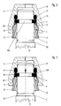
- a water fitting in the form of a single-hole water mixer fitting is shown in part, an insert 10 made of plastic being introduced into a housing 1 and being held in the plug-in position by a mixing valve cartridge 12 shown in part.
- a mixing valve cartridge 12 shown in part.
- two inlet openings arranged one behind the other - only one inlet opening is visible in the drawing plane - are provided.
- a hose line 23 with an end piece 2 is to be inserted in a sealed manner and can be locked in the plug-in position, cold water being supplied via a first hose line 23 and warm water being supplied to the mixing valve cartridge 12 via a further hose line 23, in which mixed water which is heated in a known manner is produced and can be dispensed in a water outlet, not shown in the drawing.
- a clip ring 3 made of plastic is first arranged on the end piece 2, which can be locked in the plug-in position with projections formed on resilient tongues in the connection opening 11.
- a conical disk 4 is attached to a circumferential end face 31 of the clip ring 3.
- a collar 20 designed as a snap ring is arranged in an annular groove 200 on the opposite end face of the conical disk 4.
- An O-ring 21 is slipped onto the end piece 2 on the opposite side of the collar 20.
- the end piece 2, the collar 20 and the conical disk 4 are made of metal, for example stainless steel.
- the conical shape of the conical disk 4 is converted into a plane shape in a spring-elastic manner, the conical disk 4 being supported by the outer wall of the end piece 2, as can be seen from FIG. 3 of the drawing.
- the conical disk 4 is spread radially, the circumferential end face of the conical disk 4 cutting into the wall of the connection opening 11 of the insert 10 made of plastic and forming an additional axial lock, with which high pressure surges caused by water hammer can also be absorbed.
- the conical disk 4 returns from the flat shape to the conical shape, as shown in FIG. 2, resiliently.
- the projections 30 can be deflected out of the recess 110 with the aid of actuating arms 32, so that the end piece 2 with the collar 20, the conical disk 4 and the clip ring 3 can be pulled out of the connection opening 11 to release the connection connection.
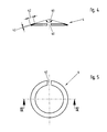
- a conical disk 4 has proven to be advantageous if it has an annular width 42 which corresponds to approximately one sixth of the outer diameter 22 of the end piece 2, an annular thickness 43 of approximately one sixth of the annular width 42 being expedient.
- the conical disk 4 can have a cone angle 41 of 90 ° to 160 °, preferably 145 °.
- the conical disk 4 is provided with a slot 40 so that a relatively smooth conversion from the conical to a planar shape and vice versa can take place.
- the conical disk 4 is made of stainless spring steel or a similar material in order to prevent corrosion in the area of the disk.
- connection connection shown in FIGS. 6 and 7 the conical disk is arranged in the reverse manner, ie the conical tip of the conical disk 4 is opposite to the direction of insertion.
- the end piece 2 of the hose line 23 with the O-ring 21 and the collar 20 is shown inserted into the connection opening 11, the clip ring 3 being located essentially in front of the connection opening 11.
- the conical disk 4 is arranged in front of the collar 20 in the relaxed state.
- the connection opening 11 and / or the clip ring 3 are dimensioned in such a way that when the clip ring 3 is pushed into its latching position in the connection opening 11, the conical disk 4 is pressed into its flat, spread shape, as shown in FIG. 7 is removed.
- connection connection shown in FIGS. 8 and 9 of the drawing differs from that shown in FIGS. 1 to 5 only in that copper pipes 24 are provided as connection lines.
- the collar 20 can be integrally formed inexpensively on the end piece 2, for example by an upsetting process.
- the conical disk 4 can be arranged with its conical tip counter to the insertion direction, but then the connection opening 11 and / or the clip ring 3 must be dimensioned in such a way as shown in FIG. 7 can be seen from the drawing.
- connection openings 11 are made of plastic.
- connection opening in one metal housing or the like.
- the conical disk 4 with the spreading process against the Wall of the connection opening 11 is pressed so that thereby the plug connection against by friction unauthorized loosening is ensured.
Abstract
Description
Die Erfindung betrifft eine Wasserarmatur, insbesondere
Einlochmischbatterie für Wasch- und/oder Spültische od.
dgl., mit einem wenigstens eine Anschlussöffnung für
den Wasserzulauf und wenigstens eine Wasserauslassöffnung
aufweisenden Gehäuse, wobei jeweils in der Anschlussöffnung
ein metallenes Endstück einer Leitung
mit jeweils wenigstens einem O-Ring gedichtet und mit
einem an einem Axialsicherungselement anliegenden Bund
in der Stecklage gehalten ist.
Eine Wasserarmatur dieser Gattung ist aus der deutschen
Offenlegungsschrift 23 04 658 bekannt. Bei dieser Wasserarmatur
ist je eine Leitung für Kaltwasser und für
Warmwasser parallel in einem durch eine Öffnung in einem
Waschtisch hindurchreichenden Sockel ausgebildete
Anschlussöffnungen gedichtet eingeführt. Dabei ist für
die axiale Sicherung eine mit Durchgangsbohrungen für
die beiden Leitungen ausgestattete Platte vorgesehen,
die mit dem Sockel am vorstehenden Bereich verschraubbar
ist. Der Verschraubvorgang und die Mittel hierzu
sind jedoch relativ aufwendig. Darüber hinaus werden
zunehmend aus Kosten- und Materialersparnisgründen Wasserarmaturen
ohne Gehäusesockel eingesetzt, bei denen
lediglich ein Spannbolzen durch die Waschtischöffnung
hindurchgreift und die Leitungen in den Armaturenkörper
oberhalb des Waschtisches geführt werden. Bei diesen
Armaturen kann es insbesondere aus Platzgründen problematisch
sein, die bekannte Platte zur axialen Fixierung
der Leitungen vorzusehen.The invention relates to a water fitting, in particular a single-hole mixer tap for washbasins and / or sinks or the like, with a housing having at least one connection opening for the water inlet and at least one water outlet opening, a metal end piece of a line with at least one O in each case in the connection opening -Ring is sealed and is held in the plug-in position with a collar resting on an axial securing element.
A water fitting of this type is known from German Offenlegungsschrift 23 04 658. In this water fitting, a line for cold water and for hot water is introduced in parallel in a sealed manner in a connection opening formed through an opening in a basin. In this case, a plate equipped with through holes for the two lines is provided for the axial securing, which plate can be screwed to the base in the projecting area. However, the screwing process and the means for this are relatively complex. In addition, water fittings without a housing base are increasingly being used for reasons of cost and material savings, in which only one clamping bolt reaches through the washbasin opening and the lines are led into the fitting body above the washbasin. With these fittings, it can be problematic, particularly for reasons of space, to provide the known plate for axially fixing the lines.
Der Erfindung liegt die Aufgabe zugrunde, für eine Wasserarmatur eine verbesserte Anschlussverbindung vorzuschlagen, die insbesondere kostengünstig realisierbar ist, wenig Platz benötigt und die auch z. B. durch Wasserschlag verursachten hohen Druckstössen standhält.The invention is based, for a water fitting the task propose an improved connection, which can be implemented particularly cost-effectively is, takes up little space and also z. B. by water hammer withstands the high pressure surges caused.
Diese Aufgabe wird erfindungsgemäss dadurch gelöst,
dass der Bund mit einer Stirnfläche an einer Kegelscheibe
anliegt, die andererseits von einem auf das
Endstück aufschiebbaren, in der Stecklage in der Anschlussöffnung
lösbar zu verrastenden Clip-Ring abgestützt
ist, wobei die Kegelscheibe so ausgebildet ist,
dass sie sich bei einer bestimmten axialen Belastung
elastisch federnd von einer kegeligen in eine plane
Form ändert und gegen die Wandung der Anschlussöffnung
gespreizt wird.
Weitere Ausgestaltungen der Erfindung sind in den Ansprüchen
2 bis 11 angegeben.This object is achieved according to the invention in that the collar rests with an end face on a conical disk which is supported on the other hand by a clip ring which can be pushed onto the end piece and releasably locked in the plug position in the connection opening, the conical disk being designed in such a way that it changes elastically resiliently from a conical shape to a flat shape at a certain axial load and is spread against the wall of the connection opening.
Further refinements of the invention are specified in
Mit den vorgeschlagenen Massnahmen wird einerseits eine
lösbare platzsparende Steckverbindung geschaffen, die
andererseits mit Hilfe der federelastisch umformbaren
Kegelscheibe hohe Axialkräfte sicher aufnehmen kann.
Die erfindungsgemässe Steckverbindung ist daher insbesondere
für den sicheren Anschluss von flexiblen Zulaufanschlussleitungen,
wie beispielsweise Druckschläuche,
geeignet. Selbstverständlich ist die Steckverbindung
ebenfalls bei Cu-Rohren mit angeformtem Bund vorteilhaft,
insbesondere dann, wenn bauseitig erforderliche
Verlängerungselemente, vorzugsweise flexible Anschlussstücke,
eingesetzt werden.
Ausführungsbeispiele der Erfindung sind in der Zeichnung
dargestellt und werden im folgenden näher beschrieben.
Es zeigt
- Fig. 1
- einen Teil einer Wasserarmatur im Längsschnitt;
- Fig. 2
- eine in Fig. 1 gezeigte Anschlussverbindung in vergrösserter Darstellung mit einer elastisch federnden Kegelscheibe in entspanntem Zustand;
- Fig. 3
- die in Fig. 2 gezeigte Anschlussverbindung mit der Kegelscheibe, die durch eine Axialbewegung elastisch in eine Planscheibe umgeformt ist, wobei der Aussenrand der Scheibe in eine Wandung einer Aufnahmebohrung einschneidet;
- Fig. 4
- die in Fig. 2 gezeigte Kegelscheibe in der Schnittebene IV der Fig. 5;
- Fig. 5
- die in Fig. 4 gezeigte Kegelscheibe in Draufsicht;
- Fig. 6
- ein anderes Ausführungsbeispiel der Anschlussverbindung mit einem gelösten Clip-Ring;
- Fig. 7
- die in Fig. 6 gezeigte Anschlussverbindung mit eingerastetem Clip-Ring, wobei die Kegelscheibe von dem Clip-Ring elastisch in eine Planscheibe umgeformt ist und die Scheibe mit ihrem Aussenrand in die Wandung einer Aufnahmebohrung einschneidet;
- Fig. 8
- ein anderes Ausführungsbeispiel der Anschlussverbindung mit einer elastisch federnden Kegelscheibe in entspanntem Zustand;
- Fig. 9
- die in Fig. 8 gezeigte Anschlussverbindung mit der Kegelscheibe, die durch eine Axialbewegung elastisch in eine Planscheibe umgeformt ist, wobei der Aussenrand der Scheibe in eine Wandung der Aufnahmebohrung einschneidet.
Embodiments of the invention are shown in the drawing and are described in more detail below. It shows
- Fig. 1
- part of a water tap in longitudinal section;
- Fig. 2
- a connection shown in Figure 1 in an enlarged view with an elastic spring cone in the relaxed state.
- Fig. 3
- the connection shown in Figure 2 with the conical disk, which is resiliently formed by an axial movement in a face plate, the outer edge of the disk cuts into a wall of a receiving bore;
- Fig. 4
- the conical disk shown in Figure 2 in the section plane IV of Fig. 5.
- Fig. 5
- the conical disk shown in Figure 4 in plan view.
- Fig. 6
- another embodiment of the connection with a detached clip ring;
- Fig. 7
- the connection shown in Fig. 6 with the snap-in clip ring, the conical disk being resiliently formed by the clip ring into a faceplate and the disk cutting into the wall of a receiving bore with its outer edge;
- Fig. 8
- another embodiment of the connection with an elastic spring cone in the relaxed state;
- Fig. 9
- the connection shown in Fig. 8 with the conical disk, which is resiliently formed by an axial movement in a face plate, the outer edge of the disk cuts into a wall of the receiving bore.
Der Einfachheit halber sind bei den Ausführungsbeispielen in der Zeichnung gleiche oder entsprechende Elemente mit jeweils gleichen Bezugszeichen versehen. For the sake of simplicity, the exemplary embodiments the same or corresponding elements in the drawing provided with the same reference numerals.
Bei dem in Fig. 1 bis 5 gezeigten Ausführungsbeispiel
ist eine Wasserarmatur in Form einer Einlochwassermischarmatur
zum Teil dargestellt, wobei in einem Gehäuse
1 ein Einsatz 10 aus Kunststoff eingebracht ist,
der von einer zum Teil dargestellten Mischventilkartusche
12 in der Stecklage gehalten wird. In dem Einsatz
10 sind zwei hintereinander angeordnete Einlassöffnungen
- in der Zeichnungsebene ist lediglich eine Einlassöffnung
sichtbar - vorgesehen.
In jeweils eine Anschlussöffnung 11 ist eine Schlauchleitung
23 mit einem Endstück 2 gedichtet einzuführen
und in der Stecklage verriegelbar, wobei über eine erste
Schlauchleitung 23 Kaltwasser und über eine weitere
Schlauchleitung 23 Warmwasser der Mischventilkartusche
12 zugeführt wird, in der in bekannter Weise temperiertes
Mischwasser erzeugt und dosiert über einen in der
Zeichnung nicht dargestellten Wasserauslauf abgegeben
werden kann.
Zur Verriegelung des Endstücks 2 in der Stecklage ist
zunächst auf dem Endstück 2 ein Clip-Ring 3 aus Kunststoff
angeordnet, der in der Stecklage mit an federnden
Zungen ausgebildeten Vorsprüngen in der Anschlussöffnung
11 verrastbar ist. An einer umlaufenden Stirnseite
31 des Clip-Rings 3 ist eine Kegelscheibe 4 angelagert.
An der gegenüberliegenden Stirnseite der Kegelscheibe 4
ist in einer Ringnut 200 ein als Sprengring ausgebildeter
Bund 20 angeordnet. An der gegenüberliegenden Seite
des Bundes 20 ist ein O-Ring 21 auf das Endstück 2 aufgestreift.
Das Endstück 2, der Bund 20 und die Kegelscheibe
4 sind aus Metall hergestellt, beispielsweise
aus Edelstahl. In the exemplary embodiment shown in FIGS. 1 to 5, a water fitting in the form of a single-hole water mixer fitting is shown in part, an
In each connection opening 11, a
To lock the
Zur Herstellung der Anschlussverbindung wird nun das
Endstück mit dem O-Ring 21, dem Bund 20, der Kegelscheibe
4, deren Kegelspitze in Einsteckrichtung zeigt,
und dem Clip-Ring 3 in die Aufnahmebohrung 11 eingeführt,
wobei der O-Ring 21 dichtend zwischen dem
Aussenmantel des Endstücks 2 der Wandung der Anschlussöffnung
21 zur Anlage gelangt. Der Clip-Ring 3
kann nun mit seinen federelastisch angeordneten Vorsprüngen
30 in eine Ausnehmung 110 in der Anschlussöffnung
11 des Einsatzes 10 eingesprengt werden, wodurch
eine erste axiale Sicherung der Steckverbindung hergestellt
wird, wie es insbesondere aus Fig. 1 und Fig. 2
ersichtlich ist.
Wird nun die Schlauchleitung 23 vom Wasserleitungsdruck
beaufschlagt, so bewirkt der anstehende Wasserdruck,
dass das Endstück 2 entgegen der Federkraft der Kegelscheibe
4 aus der Anschlussöffnung 11 herausgedrückt
wird, wobei der Clip-Ring 3 als Widerlager wirkt. Hierbei
wird die Kegelform der Kegelscheibe 4 federelastisch
in eine Planform umgewandelt, wobei die Kegelscheibe
4 von der Aussenwandung des Endstücks 2 abgestützt
wird, wie es aus Fig. 3 der Zeichnung zu entnehmen
ist. Dabei wird die Kegelscheibe 4 radial gespreizt,
wobei die umlaufende Stirnseite der Kegelscheibe
4 in die Wandung der Anschlussöffnung 11 des
aus Kunststoff hergestellten Einsatzes 10 einschneidet
und eine zusätzliche Axialsicherung bildet, mit der sicher
auch von Wasserschlägen verursachte hohe Druckstösse
aufgenommen werden können.
Wird dagegen die Schlauchleitung 23 vom Wasserleitungsdruck
entlastet, so kehrt die Kegelscheibe 4 von der
planen Form in die kegelige Form, wie sie in Fig. 2
dargestellt ist, federelastisch zurück. In dieser Stellung
können die Vorsprünge 30 mit Hilfe von Betätigungsarmen
32 aus der Ausnehmung 110 ausgelenkt werden,
so dass das Endstück 2 mit dem Bund 20, der Kegelscheibe
4 und dem Clip-Ring 3 aus der Anschlussöffnung 11
zur Lösung der Anschlussverbindung herausgezogen werden
kann.To establish the connection, the end piece with the O-
If the
On the other hand, if the
Bei der Anschlussverbindung hat sich eine Kegelscheibe
4 als günstig erwiesen, wenn sie eine Ringbreite 42
aufweist, die etwa einem Sechstel des Aussendurchmessers
22 des Endstücks 2 entspricht, wobei eine Ringdikke
43 von etwa einem Sechstel der Ringbreite 42 zweckmässig
ist.
Die Kegelscheibe 4 kann im entspannten Zustand einen
Kegelwinkel 41 von 90° bis 160°, vorzugsweise 145°,
aufweisen. Damit eine relativ leichtgängige Umwandlung
von der kegeligen in eine plane Form und umgekehrt erfolgen
kann, ist die Kegelscheibe 4 mit einem Schlitz
40 versehen. Darüber hinaus ist die Kegelscheibe 4 aus
nichtrostendem Federstahl oder einem ähnlichen Werkstoff
hergestellt, um Korrosion im Bereich der Scheibe
auszuschliessen.In the case of the connection, a
In the relaxed state, the
Im Gegensatz zu dem vorstehend beschriebenen Ausführungsbeispiel
ist bei der in Fig. 6 und 7 gezeigten Anschlussverbindung
die Kegelscheibe in umgekehrter Weise
angeordnet, d. h., die Kegelspitze der Kegelscheibe 4
ist der Einsteckrichtung entgegengerichtet. In Fig. 6
ist das Endstück 2 der Schlauchleitung 23 mit dem O-Ring
21 und dem Bund 20 in die Anschlussöffnung 11 eingeführt
gezeigt, wobei der Clip-Ring 3 sich im wesentlichen
vor der Anschlussöffnung 11 befindet. Die Kegelscheibe
4 ist im entspannten Zustand vor dem Bund 20
angeordnet.
Die Anschlussöffnung 11 und/oder der Clip-Ring 3 sind
hierbei derart bemessen, dass bei einem Einschieben des
Clip-Rings 3 in seine Rastposition in der Anschlussöffnung
11 die Kegelscheibe 4 in ihre plane gespreizte
Form gedrückt wird, wie es aus Fig. 7 zu entnehmen ist.
Mit dieser Einrichtung wird erreicht, dass unabhängig
vom anstehenden Wasserleitungsdruck die Kegelscheibe 4
allein vom Clip-Ring 3 in die gespreizte Verriegelungsposition
gebracht wird.
Bei einer Lösung der Anschlussverbindung wird der Clip-Ring
3 aus seiner Rastposition in der Anschlussöffnung
11 herausgenommen, wobei die Kegelscheibe 4 von der gespreizten
Stellung wieder in ihre entspannte kegelige
Form zurückkehrt, wie es aus Fig. 6 zu entnehmen ist.In contrast to the exemplary embodiment described above, in the connection connection shown in FIGS. 6 and 7, the conical disk is arranged in the reverse manner, ie the conical tip of the
The
When the connection is released, the
Das in Fig. 8 und 9 der Zeichnung dargestellte Ausführungsbeispiel
einer weiteren Anschlussverbindung unterscheidet
sich zu dem in Figur 1 bis 5 gezeigten lediglich
dadurch, dass als Anschlussleitungen Kupferrohre
24 vorgesehen sind. Bei Cu-Rohren 24 kann der Bund 20
kostengünstig einstückig an dem Endstück 2, z.B. durch
einen Stauchvorgang, angeformt werden.
Selbstverständlich kann auch bei der einstückigen Ausbildung
von Endstück 2 und Bund 20 die Kegelscheibe 4
mit ihrer Kegelspitze entgegen der Einsteckrichtung angeordnet
werden, wobei dann jedoch die Anschlussöffnung
11 und/oder der Clip-Ring 3 derart zu bemessen ist, wie
es aus Fig. 7 der Zeichnung zu entnehmen ist.The exemplary embodiment of a further connection connection shown in FIGS. 8 and 9 of the drawing differs from that shown in FIGS. 1 to 5 only in that
Of course, in the case of the one-piece design of
Bei den vorstehend beschriebenen Ausführungsbeispielen
ist der Einsatz 10, in dem die Anschlussöffnungen 11
ausgebildet sind, aus Kunststoff hergestellt. Selbstverständlich
kann die Anschlussöffnung auch in einem
metallenen Gehäuse od. dgl. vorgesehen werden, wobei
dann die Kegelscheibe 4 mit dem Spreizvorgang gegen die
Wandung der Anschlussöffnung 11 gepresst wird, so dass
dadurch mittels Reibschluss die Steckverbindung gegen
ein unzulässiges Lösen gesichert wird.In the exemplary embodiments described above
is the
Claims (11)
Applications Claiming Priority (2)
| Application Number | Priority Date | Filing Date | Title |
|---|---|---|---|
| DE1999141492 DE19941492A1 (en) | 1999-09-01 | 1999-09-01 | Water tap with connection |
| DE19941492 | 1999-09-01 |
Publications (2)
| Publication Number | Publication Date |
|---|---|
| EP1081297A2 true EP1081297A2 (en) | 2001-03-07 |
| EP1081297A3 EP1081297A3 (en) | 2001-03-28 |
Family
ID=7920317
Family Applications (1)
| Application Number | Title | Priority Date | Filing Date |
|---|---|---|---|
| EP00118454A Withdrawn EP1081297A3 (en) | 1999-09-01 | 2000-08-25 | Water armature with connection device |
Country Status (2)
| Country | Link |
|---|---|
| EP (1) | EP1081297A3 (en) |
| DE (1) | DE19941492A1 (en) |
Cited By (4)
| Publication number | Priority date | Publication date | Assignee | Title |
|---|---|---|---|---|
| EP1457607A3 (en) * | 2003-03-12 | 2005-09-07 | Hansgrohe AG | Device for fixing a pipe |
| WO2006043051A1 (en) * | 2004-10-19 | 2006-04-27 | Andrew Boulton Renfrew | Shower arrangement |
| WO2008120252A1 (en) * | 2007-03-30 | 2008-10-09 | Crs S.P.A. | Tap |
| EP3702540A1 (en) * | 2019-02-26 | 2020-09-02 | Grohe AG | Securing element for securing conduits in the sanitary area |
Families Citing this family (1)
| Publication number | Priority date | Publication date | Assignee | Title |
|---|---|---|---|---|
| DE102007006471B4 (en) * | 2007-02-09 | 2009-09-24 | Hansa Metallwerke Ag | Sanitary fitting, in particular a single lever mixer |
Citations (1)
| Publication number | Priority date | Publication date | Assignee | Title |
|---|---|---|---|---|
| EP0937828A2 (en) * | 1998-02-20 | 1999-08-25 | Friedrich Grohe Aktiengesellschaft | Sanitary fitting with pipe connection element |
Family Cites Families (2)
| Publication number | Priority date | Publication date | Assignee | Title |
|---|---|---|---|---|
| IN163849B (en) * | 1984-02-02 | 1988-11-26 | Bundy Tubing Of India Ltd | |
| GB2194826A (en) * | 1986-09-04 | 1988-03-16 | Canberra Mouldings Limited | Pipe coupling |
-
1999
- 1999-09-01 DE DE1999141492 patent/DE19941492A1/en not_active Withdrawn
-
2000
- 2000-08-25 EP EP00118454A patent/EP1081297A3/en not_active Withdrawn
Patent Citations (1)
| Publication number | Priority date | Publication date | Assignee | Title |
|---|---|---|---|---|
| EP0937828A2 (en) * | 1998-02-20 | 1999-08-25 | Friedrich Grohe Aktiengesellschaft | Sanitary fitting with pipe connection element |
Cited By (7)
| Publication number | Priority date | Publication date | Assignee | Title |
|---|---|---|---|---|
| EP1457607A3 (en) * | 2003-03-12 | 2005-09-07 | Hansgrohe AG | Device for fixing a pipe |
| WO2006043051A1 (en) * | 2004-10-19 | 2006-04-27 | Andrew Boulton Renfrew | Shower arrangement |
| GB2430152A (en) * | 2004-10-19 | 2007-03-21 | Andrew Boulton Renfrew | Shower arrangement |
| GB2430152B (en) * | 2004-10-19 | 2008-07-30 | Andrew Boulton Renfrew | Shower arrangement |
| US8156579B2 (en) | 2004-10-19 | 2012-04-17 | Applied Energy Products Limited | Shower arrangement |
| WO2008120252A1 (en) * | 2007-03-30 | 2008-10-09 | Crs S.P.A. | Tap |
| EP3702540A1 (en) * | 2019-02-26 | 2020-09-02 | Grohe AG | Securing element for securing conduits in the sanitary area |
Also Published As
| Publication number | Publication date |
|---|---|
| EP1081297A3 (en) | 2001-03-28 |
| DE19941492A1 (en) | 2001-03-15 |
Similar Documents
| Publication | Publication Date | Title |
|---|---|---|
| EP0681127A1 (en) | Water fitting | |
| EP0293655A1 (en) | Mixing valve | |
| DE202013103517U1 (en) | Fastening arrangement for a faucet | |
| EP0519244B1 (en) | Demountable pipe connection | |
| DE202004012795U1 (en) | Plug connection for fluid lines | |
| EP0724042A1 (en) | Water tap with mounting device | |
| EP1703191A2 (en) | Conduit coupling | |
| DE102007043309B4 (en) | plumbing fixture | |
| EP1099896A2 (en) | Connecting device for fluid conduits | |
| EP0937828A2 (en) | Sanitary fitting with pipe connection element | |
| EP1081297A2 (en) | Water armature with connection device | |
| EP0472022B1 (en) | Plug connection | |
| DE4421387B4 (en) | pillar mixer | |
| EP1249649B1 (en) | Sanitary fitting | |
| DE202008006949U1 (en) | Sanitary angle valve for connection of washbasin taps | |
| DE3231214A1 (en) | Sanitary fitting | |
| DE10157304B4 (en) | Quick coupling for pipes | |
| DE10307921B3 (en) | Plug-fit connector for fluid, steam or air line has rotary locking device for securing inserted coupling plug in coupling housing | |
| DE102007006471B4 (en) | Sanitary fitting, in particular a single lever mixer | |
| DE3014368A1 (en) | CONTROL PANEL BUILT-IN DEVICE FOR HOLE-MOUNTED INSTALLATION IN CONTROL PANELS | |
| DE10212477B4 (en) | Water faucet with a bottom plate | |
| DE102019103607A1 (en) | Connection arrangement for a fitting and method for arranging a fitting on the connection arrangement | |
| DE10049231A1 (en) | Arrangement for connecting fluid lines | |
| DE4125569C2 (en) | Mixer tap with wall connection | |
| DE10032193B4 (en) | pipe connection |
Legal Events
| Date | Code | Title | Description |
|---|---|---|---|
| PUAI | Public reference made under article 153(3) epc to a published international application that has entered the european phase |
Free format text: ORIGINAL CODE: 0009012 |
|
| PUAL | Search report despatched |
Free format text: ORIGINAL CODE: 0009013 |
|
| AK | Designated contracting states |
Kind code of ref document: A2 Designated state(s): AT BE CH CY DE DK ES FI FR GB GR IE IT LI LU MC NL PT SE |
|
| AX | Request for extension of the european patent |
Free format text: AL;LT;LV;MK;RO;SI |
|
| AK | Designated contracting states |
Kind code of ref document: A3 Designated state(s): AT BE CH CY DE DK ES FI FR GB GR IE IT LI LU MC NL PT SE |
|
| AX | Request for extension of the european patent |
Free format text: AL;LT;LV;MK;RO;SI |
|
| 17P | Request for examination filed |
Effective date: 20010831 |
|
| AKX | Designation fees paid |
Free format text: AT BE CH CY DE DK ES FI FR GB GR IE IT LI LU MC NL PT SE |
|
| RAP1 | Party data changed (applicant data changed or rights of an application transferred) |
Owner name: GROHE WATER TECHNOLOGY AG & CO. KG |
|
| 17Q | First examination report despatched |
Effective date: 20031223 |
|
| STAA | Information on the status of an ep patent application or granted ep patent |
Free format text: STATUS: THE APPLICATION IS DEEMED TO BE WITHDRAWN |
|
| 18D | Application deemed to be withdrawn |
Effective date: 20040504 |