EP1080838B1 - Handwerkzeugmaschine - Google Patents
Handwerkzeugmaschine Download PDFInfo
- Publication number
- EP1080838B1 EP1080838B1 EP00115534A EP00115534A EP1080838B1 EP 1080838 B1 EP1080838 B1 EP 1080838B1 EP 00115534 A EP00115534 A EP 00115534A EP 00115534 A EP00115534 A EP 00115534A EP 1080838 B1 EP1080838 B1 EP 1080838B1
- Authority
- EP
- European Patent Office
- Prior art keywords
- hand tool
- plastic ring
- tool according
- powered hand
- component
- Prior art date
- Legal status (The legal status is an assumption and is not a legal conclusion. Google has not performed a legal analysis and makes no representation as to the accuracy of the status listed.)
- Expired - Lifetime
Links
- 239000004033 plastic Substances 0.000 claims description 54
- 239000002184 metal Substances 0.000 claims 2
- 230000005540 biological transmission Effects 0.000 description 19
- 230000001681 protective effect Effects 0.000 description 7
- 238000003780 insertion Methods 0.000 description 5
- 230000037431 insertion Effects 0.000 description 5
- 230000033001 locomotion Effects 0.000 description 4
- 238000005452 bending Methods 0.000 description 2
- 230000006835 compression Effects 0.000 description 2
- 238000007906 compression Methods 0.000 description 2
- 238000001816 cooling Methods 0.000 description 2
- 238000007373 indentation Methods 0.000 description 2
- 239000000463 material Substances 0.000 description 2
- 238000000034 method Methods 0.000 description 2
- 238000005096 rolling process Methods 0.000 description 2
- 229910000760 Hardened steel Inorganic materials 0.000 description 1
- 241000209035 Ilex Species 0.000 description 1
- 238000005299 abrasion Methods 0.000 description 1
- XAGFODPZIPBFFR-UHFFFAOYSA-N aluminium Chemical compound [Al] XAGFODPZIPBFFR-UHFFFAOYSA-N 0.000 description 1
- 229910052782 aluminium Inorganic materials 0.000 description 1
- 239000011324 bead Substances 0.000 description 1
- 230000009286 beneficial effect Effects 0.000 description 1
- 230000006378 damage Effects 0.000 description 1
- 230000003247 decreasing effect Effects 0.000 description 1
- 230000000694 effects Effects 0.000 description 1
- 210000002414 leg Anatomy 0.000 description 1
- 239000000314 lubricant Substances 0.000 description 1
- 238000003754 machining Methods 0.000 description 1
- 230000013011 mating Effects 0.000 description 1
- 238000009527 percussion Methods 0.000 description 1
- 238000012805 post-processing Methods 0.000 description 1
- 238000012545 processing Methods 0.000 description 1
- 238000007790 scraping Methods 0.000 description 1
- 238000007789 sealing Methods 0.000 description 1
- 230000035939 shock Effects 0.000 description 1
- 210000000689 upper leg Anatomy 0.000 description 1
Images




Classifications
-
- H—ELECTRICITY
- H02—GENERATION; CONVERSION OR DISTRIBUTION OF ELECTRIC POWER
- H02K—DYNAMO-ELECTRIC MACHINES
- H02K7/00—Arrangements for handling mechanical energy structurally associated with dynamo-electric machines, e.g. structural association with mechanical driving motors or auxiliary dynamo-electric machines
- H02K7/14—Structural association with mechanical loads, e.g. with hand-held machine tools or fans
- H02K7/145—Hand-held machine tool
-
- B—PERFORMING OPERATIONS; TRANSPORTING
- B24—GRINDING; POLISHING
- B24B—MACHINES, DEVICES, OR PROCESSES FOR GRINDING OR POLISHING; DRESSING OR CONDITIONING OF ABRADING SURFACES; FEEDING OF GRINDING, POLISHING, OR LAPPING AGENTS
- B24B23/00—Portable grinding machines, e.g. hand-guided; Accessories therefor
- B24B23/04—Portable grinding machines, e.g. hand-guided; Accessories therefor with oscillating grinding tools; Accessories therefor
-
- B—PERFORMING OPERATIONS; TRANSPORTING
- B25—HAND TOOLS; PORTABLE POWER-DRIVEN TOOLS; MANIPULATORS
- B25F—COMBINATION OR MULTI-PURPOSE TOOLS NOT OTHERWISE PROVIDED FOR; DETAILS OR COMPONENTS OF PORTABLE POWER-DRIVEN TOOLS NOT PARTICULARLY RELATED TO THE OPERATIONS PERFORMED AND NOT OTHERWISE PROVIDED FOR
- B25F5/00—Details or components of portable power-driven tools not particularly related to the operations performed and not otherwise provided for
- B25F5/02—Construction of casings, bodies or handles
-
- H—ELECTRICITY
- H02—GENERATION; CONVERSION OR DISTRIBUTION OF ELECTRIC POWER
- H02K—DYNAMO-ELECTRIC MACHINES
- H02K5/00—Casings; Enclosures; Supports
- H02K5/04—Casings or enclosures characterised by the shape, form or construction thereof
- H02K5/16—Means for supporting bearings, e.g. insulating supports or means for fitting bearings in the bearing-shields
- H02K5/173—Means for supporting bearings, e.g. insulating supports or means for fitting bearings in the bearing-shields using bearings with rolling contact, e.g. ball bearings
- H02K5/1732—Means for supporting bearings, e.g. insulating supports or means for fitting bearings in the bearing-shields using bearings with rolling contact, e.g. ball bearings radially supporting the rotary shaft at both ends of the rotor
-
- H—ELECTRICITY
- H02—GENERATION; CONVERSION OR DISTRIBUTION OF ELECTRIC POWER
- H02K—DYNAMO-ELECTRIC MACHINES
- H02K5/00—Casings; Enclosures; Supports
- H02K5/24—Casings; Enclosures; Supports specially adapted for suppression or reduction of noise or vibrations
Definitions
- the invention is based on a hand tool the preamble of claim 1 or of claim 10.
- the cylindrical housing made two plastic housing shells, the edges of each one Form dividing edges that define a horizontal dividing plane.
- the housing shells are interconnected by screws connected.
- Inside the case is an electric motor with arranged a fan whose drive shaft to his Ends stored in each case via a ball bearing in the housing shells and rotatably connected to a tapered pinion.
- the pinion meshes with one of an output shaft rotatably worn conical ring gear whose axis of rotation is rectangular runs to the drive shaft.
- the output shaft has a tool-remote bearing, the a ring-like sliding bearing, which in a cylindrical Bearing receiving a housing shell is used. Furthermore owns the output shaft a tool-near bearing point, the having a sleeve-like bearing bush with a needle bearing.
- An eccentric pin carried by the tool-near end of the output shaft protrudes through the bushing from above into a hole a connecting rod-like driver, with a projection engages in a recess of an insertion tool that over a guide bearing mounted in the front region of the housing shells is.
- the invention relates to a hand tool with a arranged in a housing engine, the drive shaft which has at its ends a respective bearing in supported at least one component and a driving element is operatively connected to an insertion tool, wherein at least one bearing of the drive shaft via a part its length in the radial direction via a sliding seat directly on the component and over part of its length in radial Direction is supported by a plastic ring on the component.
- plastic ring and the component via at least one extending in the radial direction, in a recess cross-band at least against its mounting direction positively connected are.
- the drive shaft is securely fixed by the sliding seat and can also be beneficial over the rubber ring in their storage damped or can vibrations and shocks of the Rubber ring to be compensated. Furthermore, an outer ring of the Bearing through the plastic ring or rubber ring, the tolerances of the sliding seat can compensate, via a clamp be fixed radially and rotationally fixed.
- the bearing of the drive shaft over about 1/3 of its length in the sliding seat directly on the component and over about 2/3 of its length over the plastic ring or over a Rubber ring supported on the component.
- the Plastic ring is particularly easy due to a positive connection, cost-effective, without additional components safely with the component connectable.
- the perform jerky movements such as in so-called Scrape, etc., can be safely avoided the plastic ring moves in the axial direction of the component and thereby affect storage.
- the bearing is advantageously in the axial direction via a housing part fixed, whereby additional components, space, Assembly costs and costs can be saved.
- retaining elements can be easily and inexpensively attached to screw domes of the Housing often formed in the interior of the housing protrude.
- the retaining ribs can be advantageous be taken to ensure that a cooling air flow through the hand tool can flow.
- this can advantageously fixed securely be without the retaining ribs over the entire circumference extend the bearing and affect the cooling air flow.
- the plastic ring with the component at least opposite to its mounting direction is positively fixed over the entire circumference and the plastic ring at least one outer cone with an increasing in mounting direction diameter and the Housing part has a corresponding inner cone.
- the cones can be in the axial direction a desired positive engagement and also by an axial force on the plastic ring a radial force can be achieved on the bearing which fixes this particularly safe through the plastic ring becomes.
- the plastic ring becomes when mounting in the axial direction automatically in compressed radial direction, whereby the assembly is simplified can be.
- the double cone on the plastic ring could but also with an axial direction to the median plane decreasing diameter.
- this can also form fit in the circumferential direction be connected to the component, for example, by in axially extending projections.
- the component can of an additional, the bearing forces receiving Be formed directly or indirectly in the component Housing is supported.
- the component becomes advantageous formed by a housing part, whereby additional components and assembly costs can be saved.
- the camp of the Drive shaft is advantageous in a cup-shaped recess arranged. Different thermal expansions through different Materials can be avoided and a result Conditional tilting of the drive shaft can be prevented.
- the solution according to the invention can be carried out by various persons skilled in the art used as useful hand tool machines become, for example with drills, angle grinder etc. and particularly advantageous in hand tooling machines, the perform jerky movements, such as scrapers, percussion drills, Impact wrench, etc.
- Fig. 1 shows a longitudinal section through an inventive Hand tool for scraping of surfaces, briefly referred to as a scraper.
- the hand tool machine has an arranged in a housing 10 engine 12, the electrically supplied via electric cable 100 and via a Switch 102 is switched on and off.
- the electric motor 12 is via a drive shaft 14 with a fan 104 and operatively connected to an angle gear 16, namely is mounted on the drive shaft 14, a pinion 106 which with a driven by an output shaft 18 ring gear 108th meshes, the axis of rotation perpendicular to the drive shaft 14th runs.
- an eccentric pin 20 is formed, which in a connecting rod-like Carrier element 22 and an integrally formed bolt 114 in a slot 116 of an insert tool 112 engages (FIG and 3).
- the eccentric pin 20 is a roller bearing 134 in the Carrier element 22 stored.
- Through the slot 116 takes place the transmission of motion from the drive shaft 14 via the Carrier element 22 on the insert tool 112 only if the insert tool 112 placed on a work surface and as far pushed back that the bolt 114 at the edge supported the slot 116 and so his reciprocating Movement on the insert tool 112 can transmit.
- the Idling is the insert tool 112 with rotating drive shaft 14 still, so that the wear on the motion-transmitting Parts is reduced. Injuries while idling by a moving insert tool 112 avoided. Furthermore, the stationary insert tool 112 in Idling specifically at a desired location on the machined Surface are placed.
- the angle gear 16 is in a separate gearbox 24 arranged die-cast aluminum, in the front, upper Area 26 a first part and with a lid 28 in the front, lower portion 26 a second part of the housing 10th or outer walls of the power tool forms.
- the drive shaft 14 of the electric motor 12 is at a first, the insertion tool 112 facing away from a bearing 118 and via a component 120 in a first upper plastic housing shell 78 stored.
- a second, the deployment tool 112 facing the end of the drive shaft 14 is a Bearing 32 in a cup-shaped recess 34 in the transmission housing 24 stored.
- the bearing 32 is approximately in the radial direction about 1/3 of its length via a sliding seat 36 directly in the gearbox 24 and over about 2/3 of its length in radial Direction via a rubber ring 38 in the transmission housing 24 supported.
- the plastic ring 38 is connected to the transmission housing 24 in both axial directions 170, 172 positively connected (Fig. 11).
- the plastic ring 38 is in its mounting direction 170 via a front side 180 on a shoulder 190th supported in the transmission housing 24.
- the plastic ring has 38 an outer cone 178 with a mounting direction 170 increasing diameter and the gear housing 24th has in the field of plastic ring 38 a corresponding Inner cone 182. Over the cones 178, 182 is the plastic ring 38 against its mounting direction 170 positive fit connected to the transmission housing 24.
- Fig. 13 is an alternative plastic ring 166 with a extending in the radial direction and over the entire circumference Covenant 176 shown.
- Essentially consistent Components are basically in the embodiments numbered with the same reference numerals.
- the covenant 176 is centrally located, so that the plastic ring 166 to his axial center plane 186 is symmetrical and during assembly with both end faces first in the transmission housing 24th can be introduced. Misassembly is avoided.
- the Collar 176 engages in a recess 174 of the transmission housing 24 and fixes the plastic ring 166 in both axial directions 170, 172 form-fitting.
- An embodiment in Fig. 14 has a plastic ring 168 with a double cone 188, with a corresponding executed inner cone 184 in the transmission housing 24th cooperates and the plastic ring 168 in both axial Directions 170, 172 fixed positively in the gear housing 24.
- the double cone 188 has a center plane 186 a increasing in diameter and can thereby prevent the assembly of the Bearing 32 are simply inserted into the transmission housing 24.
- the plastic ring 168 is by the mounting direction 170 facing slope of the double cone 188 via an axial Assembly force automatically compressed in the radial direction.
- the plastic ring 168 is at its axial center plane 186 executed symmetrically, creating a faulty mounting is avoided.
- the output shaft 18 is at its first, the insert tool 112 facing away from a first bearing 30 directly and to her second, the insert tool 112 facing the end a second bearing 46 via a trained as adjusting means 44 Bearing mounted in the gear housing 24.
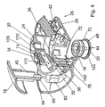
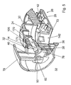
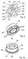
- the adjusting means 44 is via a bearing surface 70 in a cylindrical Recess 142 mounted in the transmission housing 24 ( Figures 1, 4, 5, 6, 9 and 10).
- the adjusting means 44 has a ring wedge 50 which is a housing-side Counter-ring wedge 52 assigned as a support surface is.
- the ring wedge 50 is about two screws 54, 56 against the Pressed counter-ring wedge 52, the over their screw heads 58, 60 each on a clamping surface 62 of the actuating means 44 and act on bearing surfaces 64 of the gear housing 24, of Webs are formed.
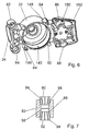
- the To avoid adjusting means 44 is the swept angle 144 from the first screw 54 to the second screw 56 and from a first screwdriver 146 to a second screwdriver 148 not equal to 180 ° (FIGS. 2 and 6).
- the clamping surface 62 has a slope in the circumferential direction or a slope and thus compensates for an axial adjustment path of the actuating means 44, so that the screw heads 58, 60 always in the parking positions on the clamping surface 62 and on the bearing surfaces 64 act.
- the clamping surface 62 is of steps 66 formed in the parking positions parallel to bearing surfaces the screw heads 58, 60 extend.
- a U-shaped guide bearing 42 for the insert tool 112 secured by a screw 124 ( Figures 3 and 8).
- molded pins 150, 152 engage in the mounted Condition positively in recesses 156, 158 a Deck side 154 of the guide bearing 42 (FIGS. 6 and 8).
- This in a punching-bending process of a hardened steel sheet manufactured guide bearing 42 is supported by end faces 160th his leg on the gear housing 24 from.
- the guide camp 42 is thus secure positive and non-positive with the transmission housing 24 connected and a post-processing of the storage areas or bearing surfaces 160 of the guide bearing 42 after The punching-bending process can be avoided.
- the driving element 22 guided against rotation (Fig. 2).
- the insert tool 112 is wear-resistant in the guide bearing 42 by four configured as needles rolling elements 126 in the longitudinal direction slidably mounted, which guided in slots 128 and a retaining plate 162 already before mounting the Guide bearing 42 held captive on the gear housing 24 are.
- the retaining plate 162 is in the U-shaped guide bearing 42 with molded-on projections 164 in recesses 74 snapped.
- the hand tool is over a protective cap 130 sealed with a felt seal 132.
- the protective cap 130 is between the transmission housing 24 and the lid 28 inserted positively, and indeed grab that Transmission housing 24 and the cover 28 between two circumferential Beads of the protective cap 130.
- the protective cap 130 is thereby particularly easy to assemble and particularly tear-proof with connected to the power tool.
- the insertion tool 112 protrudes through the protective cap 130 to the outside.
- the protective cap 130 is against wear or abrasion on the processed Surface through the lid 28 and through the transmission housing 24 protected.
- the driving element 22 via the pushbutton 110 along the eccentric pin 20 are moved against a compression spring 136, the is supported in a recess 138 on the actuating means 44.
- the Bolt 114 shifts out of the slot 116 of the insert tool 112, which removes this without tools and a alternative insert tool can be used.
- the housing 10 has next to the first upper housing shell 78, a second lower plastic housing shell 80, which in a horizontal working position in a horizontal division level 140 are joined together (Fig. 2).
- a second lower plastic housing shell 80 which in a horizontal working position in a horizontal division level 140 are joined together (Fig. 2).
- four sleeves 82, 84, 86, 88 are formed in the from top four pin 90 of the upper housing shell 78 kraftund are positively inserted ( Figures 2, 6 and 7). Further are turned from below into the two, the insertion tool 112 Sleeves 82, 84 two pins 92 of the lower housing shell 80 and in the two, the insert tool 112 facing Sleeves 86, 88 two pins of the cover 28 positive and non-positive plugged in.
- the pins 90, 92 of the housing shells 78, 80 and the pins of the lid 28 are screwed formed over which the housing shells 78, 80, the lid 28 and the transmission housing 24 via not shown Screws are bolted together.
- the housing shell 80 also grips over two pins 76 formed at gate points positively in two openings not shown in detail Lids 28.
- the sleeves 82, 84, 86, 88 are each with a double inner cone 98, in which the pins 90, 92 of the housing shells 78, 80 and the pins of the lid 28th with correspondingly shaped counter-outer cones 96 plugged are. Furthermore, pinch ribs 94 are formed on the pins 90, 92, causing the pins 90, 92 to the sleeves 82, 84, 86, 88 and a particularly advantageous Kraftund Positive locking can be achieved.
Landscapes
- Engineering & Computer Science (AREA)
- Power Engineering (AREA)
- Mechanical Engineering (AREA)
- Dental Tools And Instruments Or Auxiliary Dental Instruments (AREA)
- Drilling And Boring (AREA)
- Sawing (AREA)
- Connection Of Motors, Electrical Generators, Mechanical Devices, And The Like (AREA)
- Mounting Of Bearings Or Others (AREA)
- Harvester Elements (AREA)
Description
- Fig. 1
- einen Längsschnitt durch eine erfindungsgemäße Handwerkzeugmaschine,
- Fig. 2
- eine geöffnete Handwerkzeugmaschine nach Fig. 1 von unten,
- Fig. 3
- einen vergrößerten Ausschnitt III aus Fig. 1 mit einem montierten Einsatzwerkzeug,
- Fig. 4
- einen Ausschnitt des vorderen Bereichs einer Handwerkzeugmaschine nach Fig. 1 vor der Montage einer oberen Gehäuseschale,
- Fig. 5
- einen Ausschnitt des vorderen Bereichs nach Fig. 4 nach der Montage der oberen Gehäuseschale,
- Fig. 6
- ein Getriebegehäuse schräg von unten,
- Fig. 7
- einen Schnitt durch eine Hülse bei der Montage,
- Fig. 8
- ein Führungslager schräg von oben,
- Fig. 9
- ein Stellmittel schräg von unten,
- Fig. 10
- ein Stellmittel schräg von oben,
- Fig. 11
- einen vergrößerten Ausschnitt XI aus Fig. 1,
- Fig. 12
- einen Kunststoffring aus Fig. 11 in einer Seitenansicht,
- Fig. 13
- eine Variante nach Fig. 11 mit einem gestuften Kunststoffring und
- Fig. 14
- eine Variante nach Fig. 11, die einen Kunststoffring mit einem Doppelkonus aufweist.
- 10
- Gehäuse
- 12
- Motor
- 14
- Antriebswelle
- 16
- Winkelgetriebe
- 18
- Abtriebswelle
- 20
- Exzenter
- 22
- Mitnahmeelement
- 24
- Getriebegehäuse
- 26
- Bereich
- 28
- Deckel
- 30
- Lager
- 32
- Lager
- 34
- Ausnehmung
- 36
- Schiebesitz
- 38
- Kunststoffring
- 40
- Gehäuseteil
- 42
- Führungslager
- 44
- Stellmittel
- 46
- Lager
- 48
- Fläche
- 50
- Ringkeil
- 52
- Gegen-Ringkeil
- 54
- Schraube
- 56
- Schraube
- 58
- Schraubenkopf
- 60
- Schraubenkopf
- 62
- Klemmfläche
- 64
- Auflagefläche
- 66
- Stufe
- 68
- Verdrehsicherung
- 70
- Lagerfläche
- 72
- Einstich
- 74
- Ausnehmung
- 76
- Zapfen
- 78
- Gehäuseschale
- 80
- Gehäuseschale
- 82
- Hülse
- 84
- Hülse
- 86
- Hülse
- 88
- Hülse
- 90
- Zapfen
- 92
- Zapfen
- 94
- Quetschrippe
- 96
- Außenkonus
- 98
- Gegen-Doppelinnenkonus
- 100
- Elektrokabel
- 102
- Schalter
- 104
- Lüfterrad
- 106
- Ritzel
- 108
- Tellerrad
- 110
- Drucktaste
- 112
- Einsatzwerkzeug
- 114
- Bolzen
- 116
- Langloch
- 118
- Lager
- 120
- Bauteil
- 122
- Bund
- 124
- Schraube
- 126
- Wälzkörper
- 128
- Loch
- 130
- Schutzkappe
- 132
- Filzdichtung
- 134
- Wälzlager
- 136
- Druckfeder
- 138
- Einbuchtung
- 140
- Teilungsebene
- 142
- Ausnehmung
- 144
- Winkel
- 146
- Schraubendom
- 148
- Schraubendom
- 150
- Teil
- 152
- Teil
- 154
- Teil
- 156
- Ausnehmung
- 158
- Ausnehmung
- 160
- Stirnseite
- 162
- Halteblech
- 164
- Vorsprung
- 166
- Kunststoffring
- 168
- Kunststoffring
- 170
- Richtung
- 172
- Richtung
- 174
- Ausnehmung
- 176
- Bund
- 178
- Konus
- 180
- Stirnseite
- 182
- Innenkonus
- 184
- Innenkonus
- 186
- Mittelebene
- 188
- Doppelkonus
- 190
- Absatz
- 192
- Steg
Claims (19)
- Handwerkzeugmaschine mit einem in einem Gehäuse (10) angeordneten Motor (12), der eine Antriebswelle (14) aufweist, die an ihren Enden über jeweils ein Lager (32, 118) in zumindest einem Bauteil (24, 120) abgestützt und über ein Mitnahmeelement (22) mit einem Einsatzwerkzeug (112) wirkungsmäßig verbunden ist, wobei zumindest ein Lager (32) der Antriebswelle (14) über einen Teil seiner Länge in radialer Richtung über einen Schiebesitz (36) direkt am Bauteil (24) und über einen Teil seiner Länge in radialer Richtung über einen Kunststoffring (38, 166) am Bauteil (24) abgestützt ist, dadurch gekennzeichnet, daß der Kunststoffring (166) und das Bauteil (24) über zumindest einen sich in radialer Richtung erstreckenden, in eine Ausnehmung (174) greifenden Bund (176) zumindest entgegen seiner Montagerichtung (170) formschlüssig verbunden sind.
- Handwerkzeugmaschine nach Anspruch 1, dadurch gekennzeichnet, daß der Kunststoffring (166) über den gesamten Umfang formschlüssig fixiert ist.
- Handwerkzeugmaschine nach einem der vorhergehenden Ansprüche, dadurch gekennzeichnet, daß der Kunststoffring (166) zu seiner axialen Mittelebene (186) symmetrisch ausgeführt ist.
- Handwerkzeugmaschine nach einem der vorhergehenden Ansprüche, dadurch gekennzeichnet, daß der Kunststoffring (166) in Umfangsrichtung formschlüssig mit dem Bauteil (24) verbunden ist.
- Handwerkzeugmaschine nach einem der vorhergehenden Ansprüche, dadurch gekennzeichnet, daß das Bauteil (24) von einem Getriebegehäuse gebildet ist.
- Handwerkzeugmaschine nach einem der vorhergehenden Ansprüche, dadurch gekennzeichnet, daß das Lager (32) der Antriebswelle (14) in eine topfförmige Ausnehmung (34) im Getriebegehäuse (24) eingesetzt ist.
- Handwerkzeugmaschine nach Anspruch 5 oder 6, dadurch gekennzeichnet, daß das Getriebegehäuse (24) aus Metall ist.
- Handwerkzeugmaschine nach einem der Ansprüche 5 bis 7, dadurch gekennzeichnet, daß das Getriebegehäuse (24) im vorderen Bereich (26) zumindest einen Teil des Gehäuses (10) bildet.
- Handwerkzeugmaschine nach einem der vorhergehenden Ansprüche, dadurch gekennzeichnet, daß das Lager (32) der Antriebswelle (14) in zumindest einer axialen Richtung (172) über ein Gehäuseteil (40) fixiert ist.
- Handwerkzeugmaschine mit einem in einem Gehäuse (10) angeordneten Motor (12), der eine Antriebswelle (14) aufweist, die an ihren Enden über jeweils ein Lager (32, 118) in zumindest einem Bauteil (24, 120) abgestützt und über ein Mitnahmeelement (22) mit einem Einsatzwerkzeug (112) wirkungsmäßig verbunden ist, wobei zumindest ein Lager (32) der Antriebswelle (14) über einen Teil seiner Länge in radialer Richtung über einen Schiebesitz (36) direkt am Bauteil (24) und über einen Teil seiner Länge in radialer Richtung über einen Kunststoffring (38, 168) am Bauteil (24) abgestützt ist, dadurch gekennzeichnet, dass der Kunststoffring (38, 168) mit dem Bauteil (24) zumindest entgegen seiner Montagerichtung (170) über den gesamten Umfang formschlüssig fixiert ist und der Kunststoffring (38, 168) zumindest einen Außenkonus (178) mit einem in Montagerichtung (170) zunehmenden Durchmesser und das Bauteil (24) einen entsprechenden Innenkonus (182) aufweist.
- Handwerkzeugmaschine nach Anspruch 10, dadurch gekennzeichnet, daß der Kunststoffring (168) zu seiner axialen Mittelebene (186) symmetrisch ausgeführt ist.
- Handwerkzeugmaschine nach Anspruch 11, dadurch gekennzeichnet, daß der Kunststoffring (168) zumindest einen Doppelkonus (188) aufweist.
- Handwerkzeugmaschine nach Anspruch 12, dadurch gekennzeichnet, daß der Doppelkonus (188) des Kunststoffrings (168) in axialer Richtung (170, 172) zu seiner Mittelebene (186) einen zunehmenden Durchmesser aufweist.
- Handwerkzeugmaschine nach einem der Ansprüche 10 bis 13, dadurch gekennzeichnet, daß der Kunststoffring (168) in Umfangsrichtung formschlüssig mit dem Bauteil (24) verbunden ist.
- Handwerkzeugmaschine nach einem der Ansprüche 10 bis 14, dadurch gekennzeichnet, daß das Bauteil (24) von einem Getriebegehäuse gebildet ist.
- Handwerkzeugmaschine nach einem der Ansprüche 10 bis 15, dadurch gekennzeichnet, daß das Lager (32) der Antriebswelle (14) in eine topfförmige Ausnehmung (34) im Getriebegehäuse (24) eingesetzt ist.
- Handwerkzeugmaschine nach Anspruch 15 oder 16, dadurch gekennzeichnet, daß das Getriebegehäuse (24) aus Metall ist.
- Handwerkzeugmaschine nach einem der Ansprüche 15 bis 17, dadurch gekennzeichnet, daß das Getriebegehäuse (24) im vorderen Bereich (26) zumindest einen Teil des Gehäuses (10) bildet.
- Handwerkzeugmaschine nach einem der Ansprüche 10 bis 18, dadurch gekennzeichnet, daß das Lager (32) der Antriebswelle (14) in zumindest einer axialen Richtung (172) über ein Gehäuseteil (40) fixiert ist.
Applications Claiming Priority (2)
| Application Number | Priority Date | Filing Date | Title |
|---|---|---|---|
| DE19939171 | 1999-08-20 | ||
| DE19939171A DE19939171A1 (de) | 1999-08-20 | 1999-08-20 | Handwerkzeugmaschine |
Publications (3)
| Publication Number | Publication Date |
|---|---|
| EP1080838A2 EP1080838A2 (de) | 2001-03-07 |
| EP1080838A3 EP1080838A3 (de) | 2002-06-05 |
| EP1080838B1 true EP1080838B1 (de) | 2005-03-30 |
Family
ID=7918801
Family Applications (1)
| Application Number | Title | Priority Date | Filing Date |
|---|---|---|---|
| EP00115534A Expired - Lifetime EP1080838B1 (de) | 1999-08-20 | 2000-07-19 | Handwerkzeugmaschine |
Country Status (3)
| Country | Link |
|---|---|
| US (1) | US6810970B1 (de) |
| EP (1) | EP1080838B1 (de) |
| DE (2) | DE19939171A1 (de) |
Families Citing this family (15)
| Publication number | Priority date | Publication date | Assignee | Title |
|---|---|---|---|---|
| EP1327497B1 (de) * | 2002-01-10 | 2006-05-31 | Black & Decker Inc. | Getriebegehäuse |
| DE102005032888A1 (de) * | 2005-07-14 | 2007-01-18 | Schaeffler Kg | Sicherung eines Lagerringes |
| USD586636S1 (en) * | 2007-08-13 | 2009-02-17 | Robert Bosch Gmbh | Hand-held power cutting tool |
| RU2013119819A (ru) * | 2010-10-04 | 2014-11-20 | Роберт Бош Гмбх | Осциллирующая ручная машина |
| DE102010063069A1 (de) * | 2010-12-14 | 2012-06-14 | Robert Bosch Gmbh | Handwerkzeugmaschine, insbesondere Bohrmaschine oder Schraubbohrmaschine |
| USD651882S1 (en) * | 2011-03-08 | 2012-01-10 | Fenghua Weilder Electric Appliance Co., Ltd. | Electric circular saw |
| CN104395038B (zh) | 2012-07-03 | 2016-12-14 | 阿特拉斯·科普柯工业技术公司 | 电动工具 |
| JP6068134B2 (ja) * | 2012-12-27 | 2017-01-25 | リョービ株式会社 | 電動工具 |
| US9204750B1 (en) * | 2014-09-05 | 2015-12-08 | Louis Qussar | Electric hand held fruit and vegetable coring device |
| DE102015210058A1 (de) * | 2015-06-01 | 2016-12-01 | Robert Bosch Gmbh | Handwerkzeugmaschine |
| JP6727828B2 (ja) * | 2016-02-05 | 2020-07-22 | 株式会社マキタ | 動力工具 |
| US12528175B2 (en) * | 2020-05-21 | 2026-01-20 | Nanjing Chervon Industry Co., Ltd. | Switch structure for an electric tool |
| EP4335595A1 (de) * | 2022-04-27 | 2024-03-13 | Milwaukee Electric Tool Corporation | Elektrowerkzeug mit lagerhalter |
| WO2024107385A1 (en) * | 2022-11-18 | 2024-05-23 | Insurgical, Inc. | Medical tool with vibration damping |
| CN115890926B (zh) * | 2023-02-24 | 2023-06-30 | 刘佳 | 一种建设工程用混凝土墙面定位钻孔装置 |
Family Cites Families (18)
| Publication number | Priority date | Publication date | Assignee | Title |
|---|---|---|---|---|
| US3095248A (en) * | 1960-01-09 | 1963-06-25 | Electrolux Ab | Bearing mount for rotatable machines |
| DE2104452B2 (de) * | 1971-01-30 | 1981-03-12 | Siemens AG, 1000 Berlin und 8000 München | Anordnung zum Halten eines ein Wellenende aufnehmenden Wälzlagers, insbesondere Kugellagers |
| DE2400902C2 (de) * | 1974-01-09 | 1982-05-27 | A. Friedr. Flender Gmbh & Co Kg, 4290 Bocholt | Wälzlagereinbau |
| US3873863A (en) * | 1974-02-25 | 1975-03-25 | Singer Co | Double insulated electrically powered hand tool and coupler therefor |
| DE2516406C3 (de) * | 1975-04-15 | 1981-11-19 | Robert Bosch Gmbh, 7000 Stuttgart | Bohrhammer |
| US4334439A (en) * | 1980-05-05 | 1982-06-15 | Jack Kadymir | Power transmission device for plural power-driven hand-held tools |
| US4601591A (en) * | 1984-05-14 | 1986-07-22 | The Garrett Corporation | Elastomeric bearing damper apparatus and associated methods |
| US4549823A (en) * | 1984-05-29 | 1985-10-29 | Caterpillar Tractor Co. | Bearing race retention device and method |
| DE8624918U1 (de) * | 1986-09-18 | 1988-01-28 | Robert Bosch Gmbh, 7000 Stuttgart | Filz-Gleitringdichtung für Handwerkzeugmaschinen |
| US4991472A (en) * | 1988-11-04 | 1991-02-12 | James Curtis Hilliard | D.C. direct drive impact wrench |
| DE4003031A1 (de) * | 1990-02-02 | 1991-08-08 | Bosch Gmbh Robert | Handwerkzeugmaschine mit schnellaufendem, innenbelueftetem elektromotor |
| DE4241827A1 (de) * | 1992-12-11 | 1994-06-16 | Teves Gmbh Alfred | Geräuschreduziertes Pumpenaggregat, insbesondere für geregelte Bremsanlagen |
| DE4317062C2 (de) * | 1993-05-21 | 1995-08-17 | Freudenberg Carl Fa | Kardanwellenlager |
| NZ279471A (en) * | 1994-02-08 | 1998-02-26 | Plastic Bearings & Housings Au | Bearing; structural details of a plain bearing |
| DE19547332A1 (de) * | 1995-12-19 | 1997-06-26 | Bosch Gmbh Robert | Elektrohandwerkzeugmaschine |
| US5791789A (en) * | 1997-04-24 | 1998-08-11 | United Technologies Corporation | Rotor support for a turbine engine |
| AU7688498A (en) * | 1997-05-19 | 1998-12-11 | Stephen S. Daniell | Powered cutting saw system and method for joining materials |
| US6331078B1 (en) * | 1998-12-23 | 2001-12-18 | United Technologies Corporation | Turbine engine bearing |
-
1999
- 1999-08-20 DE DE19939171A patent/DE19939171A1/de not_active Ceased
-
2000
- 2000-07-19 DE DE50009899T patent/DE50009899D1/de not_active Expired - Lifetime
- 2000-07-19 EP EP00115534A patent/EP1080838B1/de not_active Expired - Lifetime
- 2000-08-16 US US09/639,324 patent/US6810970B1/en not_active Expired - Fee Related
Also Published As
| Publication number | Publication date |
|---|---|
| DE50009899D1 (de) | 2005-05-04 |
| EP1080838A3 (de) | 2002-06-05 |
| EP1080838A2 (de) | 2001-03-07 |
| US6810970B1 (en) | 2004-11-02 |
| DE19939171A1 (de) | 2001-03-08 |
Similar Documents
| Publication | Publication Date | Title |
|---|---|---|
| EP2334473B1 (de) | Handwerkzeugmaschine mit automatischer spindelarretierung | |
| EP3431815B1 (de) | Riemenspannvorrichtung | |
| EP1080838A2 (de) | Handwerkzeugmaschine | |
| DE19540396A1 (de) | Bohr- und/oder Meisselgerät | |
| DE602004001084T2 (de) | Kreuzgelenk mit entlüftender Dichtung | |
| DE3140373A1 (de) | Radlagereinheit fuer angetriebene raeder von kraftfahrzeugen | |
| DE69301050T2 (de) | Exzentrische Kurbelwelle für einen Luftverdichter mit Verdrängerkolben | |
| EP1259357B1 (de) | Werkzeugmaschine | |
| DE20119835U1 (de) | Handwerkzeugmaschine mit Spindelstop | |
| EP1077106B1 (de) | Handwerkzeugmaschine | |
| EP1075402B1 (de) | Wischerlager | |
| EP2252431B1 (de) | Handwerkzeugmaschine, insbesondere handgeführte schleifmaschine | |
| DE19540391A1 (de) | Bohr- und Meisselgerät | |
| CH695487A5 (de) | Werkzeugmaschine mit einem Getrieberaum mit Schmiermittel und einer Druckausgleichseinrichtung des Getrieberaums. | |
| DE102006013696A1 (de) | Scheibenwischerantriebsanordnung | |
| DE19581436C1 (de) | Klemmgesperre | |
| DE69625985T2 (de) | Axial-komprimierbares Lager für einen Scheibenwischermechanismus | |
| DE10203006B4 (de) | Beschlag für einen Fahrzeugsitz | |
| EP3976316B1 (de) | Handwerkzeugmaschine | |
| EP1077107B1 (de) | Handwerkzeugmaschine | |
| DE10243288A1 (de) | Werkzeugaufnahme | |
| EP1420193B1 (de) | Spannvorrichtung für einen Riementrieb von Hilfsaggregaten | |
| EP4424467B1 (de) | Elektrowerkzeug | |
| DE19938175B4 (de) | Handwerkzeugmaschine mit einem Führungslager für ein Einsatzwerkzeug | |
| DE19639593B4 (de) | Wischervorrichtung |
Legal Events
| Date | Code | Title | Description |
|---|---|---|---|
| PUAI | Public reference made under article 153(3) epc to a published international application that has entered the european phase |
Free format text: ORIGINAL CODE: 0009012 |
|
| AK | Designated contracting states |
Kind code of ref document: A2 Designated state(s): AT BE CH CY DE DK ES FI FR GB GR IE IT LI LU MC NL PT SE |
|
| AX | Request for extension of the european patent |
Free format text: AL;LT;LV;MK;RO;SI |
|
| PUAL | Search report despatched |
Free format text: ORIGINAL CODE: 0009013 |
|
| AK | Designated contracting states |
Kind code of ref document: A3 Designated state(s): AT BE CH CY DE DK ES FI FR GB GR IE IT LI LU MC NL PT SE |
|
| AX | Request for extension of the european patent |
Free format text: AL;LT;LV;MK;RO;SI |
|
| RIC1 | Information provided on ipc code assigned before grant |
Free format text: 7B 24B 23/04 A, 7B 25F 5/02 B, 7B 25F 5/00 B, 7H 02K 5/173 B, 7F 16C 35/077 B |
|
| 17P | Request for examination filed |
Effective date: 20021205 |
|
| AKX | Designation fees paid |
Designated state(s): DE FR GB |
|
| 17Q | First examination report despatched |
Effective date: 20031107 |
|
| GRAP | Despatch of communication of intention to grant a patent |
Free format text: ORIGINAL CODE: EPIDOSNIGR1 |
|
| GRAA | (expected) grant |
Free format text: ORIGINAL CODE: 0009210 |
|
| GRAS | Grant fee paid |
Free format text: ORIGINAL CODE: EPIDOSNIGR3 |
|
| AK | Designated contracting states |
Kind code of ref document: B1 Designated state(s): DE FR GB |
|
| REG | Reference to a national code |
Ref country code: GB Ref legal event code: FG4D Free format text: NOT ENGLISH |
|
| REF | Corresponds to: |
Ref document number: 50009899 Country of ref document: DE Date of ref document: 20050504 Kind code of ref document: P |
|
| REG | Reference to a national code |
Ref country code: IE Ref legal event code: FG4D Free format text: LANGUAGE OF EP DOCUMENT: GERMAN |
|
| GBT | Gb: translation of ep patent filed (gb section 77(6)(a)/1977) |
Effective date: 20050725 |
|
| PLBE | No opposition filed within time limit |
Free format text: ORIGINAL CODE: 0009261 |
|
| STAA | Information on the status of an ep patent application or granted ep patent |
Free format text: STATUS: NO OPPOSITION FILED WITHIN TIME LIMIT |
|
| ET | Fr: translation filed | ||
| 26N | No opposition filed |
Effective date: 20060102 |
|
| PGFP | Annual fee paid to national office [announced via postgrant information from national office to epo] |
Ref country code: FR Payment date: 20110729 Year of fee payment: 12 |
|
| PGFP | Annual fee paid to national office [announced via postgrant information from national office to epo] |
Ref country code: GB Payment date: 20110721 Year of fee payment: 12 |
|
| GBPC | Gb: european patent ceased through non-payment of renewal fee |
Effective date: 20120719 |
|
| REG | Reference to a national code |
Ref country code: FR Ref legal event code: ST Effective date: 20130329 |
|
| PG25 | Lapsed in a contracting state [announced via postgrant information from national office to epo] |
Ref country code: GB Free format text: LAPSE BECAUSE OF NON-PAYMENT OF DUE FEES Effective date: 20120719 Ref country code: FR Free format text: LAPSE BECAUSE OF NON-PAYMENT OF DUE FEES Effective date: 20120731 |
|
| PGFP | Annual fee paid to national office [announced via postgrant information from national office to epo] |
Ref country code: DE Payment date: 20130926 Year of fee payment: 14 |
|
| REG | Reference to a national code |
Ref country code: DE Ref legal event code: R119 Ref document number: 50009899 Country of ref document: DE |
|
| PG25 | Lapsed in a contracting state [announced via postgrant information from national office to epo] |
Ref country code: DE Free format text: LAPSE BECAUSE OF NON-PAYMENT OF DUE FEES Effective date: 20150203 |
|
| REG | Reference to a national code |
Ref country code: DE Ref legal event code: R119 Ref document number: 50009899 Country of ref document: DE Effective date: 20150203 |