EP1080760A2 - Anker für Ständer eines Spielgeräts - Google Patents
Anker für Ständer eines Spielgeräts Download PDFInfo
- Publication number
- EP1080760A2 EP1080760A2 EP00113878A EP00113878A EP1080760A2 EP 1080760 A2 EP1080760 A2 EP 1080760A2 EP 00113878 A EP00113878 A EP 00113878A EP 00113878 A EP00113878 A EP 00113878A EP 1080760 A2 EP1080760 A2 EP 1080760A2
- Authority
- EP
- European Patent Office
- Prior art keywords
- anchor
- stand
- ring
- anchor according
- screw
- Prior art date
- Legal status (The legal status is an assumption and is not a legal conclusion. Google has not performed a legal analysis and makes no representation as to the accuracy of the status listed.)
- Granted
Links
- 239000002184 metal Substances 0.000 claims description 8
- 241000251468 Actinopterygii Species 0.000 abstract 3
- 238000010276 construction Methods 0.000 description 1
Images

Classifications
-
- E—FIXED CONSTRUCTIONS
- E04—BUILDING
- E04H—BUILDINGS OR LIKE STRUCTURES FOR PARTICULAR PURPOSES; SWIMMING OR SPLASH BATHS OR POOLS; MASTS; FENCING; TENTS OR CANOPIES, IN GENERAL
- E04H12/00—Towers; Masts or poles; Chimney stacks; Water-towers; Methods of erecting such structures
- E04H12/22—Sockets or holders for poles or posts
- E04H12/2207—Sockets or holders for poles or posts not used
- E04H12/2215—Sockets or holders for poles or posts not used driven into the ground
- E04H12/223—Sockets or holders for poles or posts not used driven into the ground with movable anchoring elements; with separately driven anchor rods
-
- A—HUMAN NECESSITIES
- A63—SPORTS; GAMES; AMUSEMENTS
- A63G—MERRY-GO-ROUNDS; SWINGS; ROCKING-HORSES; CHUTES; SWITCHBACKS; SIMILAR DEVICES FOR PUBLIC AMUSEMENT
- A63G9/00—Swings
Definitions
- the invention relates to an anchor for stands of a game device.
- Field of application of the invention are play equipment, in particular swings, whose stands on the Stand floor, i.e. are not embedded in the floor.
- Such play equipment can be on the floor slip easily, lift off on one side or move otherwise.
- the object of the invention is to fix and fix such play equipment.
- the invention differs from the prior art in that the stand by the anchor can be fixed immovably on the floor.
- the invention is based on a swing with a wooden frame explained.
- the invention is also in play equipment with a metal tube frame or in other play equipment applicable.
- the anchor can be securely clamped to the stand that the tabs passages for a tensioning element, e.g. have a screw.
- the ring have a passage for receiving a screw.
- a compact design of the anchor is achieved in that the approach in one piece as an extension a tab is formed.
- the approach can be combined with the anchor that the approach as a ring bolt is designed to tension the tabs.
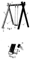
- Fig. 1 shows a swing in wooden construction with a bar 1, which is on a right and a left frame 2, 3 of two stands 4 rests.
- the stand 4 of each frame 2, 3 are through Braces not shown are braced.
- the swing seat 5 hangs on the beam 1.
- the stand 4 is at rest without additional fixation on the floor, e.g. a slab or a lawn. By the rocking movement or other influences, the swing can shift on the floor or in another Move wise what is undesirable.
- An anchor 6 enables each strut to be fixed to the floor. Man can use two to four anchors. Two anchors can e.g. attached to diagonal struts
- Fig. 3 shows in detail a first embodiment of an anchor 6.
- the anchor 6 is as Stamped-bent part formed from a sheet metal strip.
- the sheet metal strip is with a clamp-like ring 7 two different lengths 8, 9 shaped. Aligned passages 10 of both tabs 8, 9 take a threaded shaft 11 of a screw 12. A nut 13 allows tightening the Screw connection.
- the ring 7 has a passage 14.
- the longer flap 9 ends in a flat extension 16 via an entanglement 15 of approximately 90 ° with a passage 17.
- FIG. 6 shows an earth nail 18 which is pushed through the passage 17 can be.
- the ring 7 of the armature 6 is pushed according to FIG. 2 over the foot end of a stand 4 and so aligned that the approach 16 rests on the floor.
- the screw 12 By means of the screw 12, the ring 7 is firmly on the stand 4 excited.
- the earth nail 18 is inserted through the passage 17 and with an impact tool driven into the ground like a hammer 19.
- a screw 20 is through the passage 14 screwed into the stand 4 and thus fixes the anchor 6 against rotation on the stand 4.
- An anchor can be placed on a stand. You can also use two diagonally Arrange the stand anchor. It is also possible to anchor three or four stands with anchors.
- Fig. 4 shows a modified embodiment of an anchor 6, in which the tabs 8, 9 of the Rings 7 are the same length.
- the approach with the passage 17 for the earth nail is also with a sheet metal web 21 an entanglement 22 is formed.
- the end 23 of the sheet metal web 21 is on the screw shaft 11 pushed and clamped by the screw connection. This training of the approach as a separate Sheet metal web 21 allows an additional adjustment and alignment of the approach with respect to the stand and the floor.
Landscapes
- Engineering & Computer Science (AREA)
- Architecture (AREA)
- Civil Engineering (AREA)
- Structural Engineering (AREA)
- Toys (AREA)
- Stringed Musical Instruments (AREA)
- Joining Of Building Structures In Genera (AREA)
- Massaging Devices (AREA)
- Rear-View Mirror Devices That Are Mounted On The Exterior Of The Vehicle (AREA)
- Dowels (AREA)
- Auxiliary Devices For Music (AREA)
- Clamps And Clips (AREA)
- Pinball Game Machines (AREA)
- Coin-Freed Apparatuses For Hiring Articles (AREA)
Abstract
Description
Claims (8)
- Anker für Ständer eines Spielgeräts, dadurch gekennzeichnet, daß ein Ring (7) mit Laschen (8, 9) schellenartig am Fuß eines Ständers (4) festspannbar ist und daß ein Ansatz (16) des Ankers (1) einen Durchgang (17) für einen Erdnagel (18) aufweist.
- Anker nach Anspruch 1, dadurch gekennzeichnet, daß die Laschen (8, 9) Durchgänge (10) für ein Spannelement aufweisen.
- Anker nach Anspruch 2, dadurch gekennzeichnet, daß das Spannelement als Schraube (12) ausgebildet ist.
- Anker nach einem der Ansprüch 1 bis 3, dadurch gekennzeichnet, daß der Ring (7) einen Durchgang (14) zur Aufnahme einer Schraube (20) aufweist.
- Anker nach einem der Ansprüche 1 bis 4, dadurch gekennzeichnet, daß der Ansatz (16) einstückig als Verlängerung einer Lasche (9) ausgebildet ist.
- Anker nach Anspruch 5, dadurch gekennzeichnet, daß der Ansatz (16) eine Verschränkung (15) aufweist.
- Anker nach einem der Ansprüche 1 bis 4, dadurch gekennzeichnet, daß der Ansatz als Blechsteg (21) mit einer Verschränkung (22) ausgebildet ist.
- Anker nach einem der Ansprüche 1 bis 4, dadurch gekennzeichnet, daß der Ansatz als Ring (25) einer Ringschraube (24) zum Verspannen der Laschen (8, 9) ausgebildet ist.
Applications Claiming Priority (2)
| Application Number | Priority Date | Filing Date | Title |
|---|---|---|---|
| DE29915442U DE29915442U1 (de) | 1999-09-02 | 1999-09-02 | Anker für Ständer eines Spielgeräts |
| DE29915442U | 1999-09-02 |
Publications (3)
| Publication Number | Publication Date |
|---|---|
| EP1080760A2 true EP1080760A2 (de) | 2001-03-07 |
| EP1080760A3 EP1080760A3 (de) | 2002-06-05 |
| EP1080760B1 EP1080760B1 (de) | 2005-03-16 |
Family
ID=8078381
Family Applications (1)
| Application Number | Title | Priority Date | Filing Date |
|---|---|---|---|
| EP00113878A Expired - Lifetime EP1080760B1 (de) | 1999-09-02 | 2000-06-30 | Anker für Ständer eines Spielgeräts |
Country Status (4)
| Country | Link |
|---|---|
| EP (1) | EP1080760B1 (de) |
| AT (1) | ATE290916T1 (de) |
| DE (2) | DE29915442U1 (de) |
| PL (1) | PL197676B1 (de) |
Family Cites Families (16)
| Publication number | Priority date | Publication date | Assignee | Title |
|---|---|---|---|---|
| US1557940A (en) | 1924-12-27 | 1925-10-20 | Plant Peter J La | Swing |
| US1812947A (en) | 1930-01-27 | 1931-07-07 | Humane Stanchion Works | Swing |
| DE670438C (de) | 1933-12-22 | 1939-01-18 | Josef Mitterer | Einrichtung zur Befestigung eines Leitungstraegers an einem runden Holzmast |
| US2295431A (en) * | 1940-02-06 | 1942-09-08 | Ralph H Shepard | Anchor |
| US2826281A (en) | 1954-03-09 | 1958-03-11 | Albert C Green | Support or anchors for vertical columns or the like |
| US3295274A (en) * | 1964-12-10 | 1967-01-03 | Kalb Toys Inc De | Combination of pole anchor with a gym set or the like |
| US3840203A (en) * | 1973-08-17 | 1974-10-08 | F Sheehy | Base plate for outdoor gym sets |
| DE8005495U1 (de) | 1980-02-29 | 1980-09-04 | Friedrich Hoeppe Gmbh, 5870 Hemer | Schaukelaufhaenger |
| US4706921A (en) | 1986-01-17 | 1987-11-17 | Paullin Dale W | Antenna post base support and method of installing same |
| DE4116738A1 (de) * | 1991-05-23 | 1992-11-26 | Baumann Verwertungs Gmbh | Vorrichtung zum verankern einer geraetschaft, insbesondere eine schnurgerueststuetze, im erdboden |
| GB2258665B (en) * | 1991-08-08 | 1995-04-19 | Harrod Limited R | Ground anchor |
| DE9308128U1 (de) | 1993-05-29 | 1993-10-07 | Baumann, Dieter, 77815 Bühl | Multifunktionales Schaukel- und Spielgerät |
| FR2712199B1 (fr) * | 1993-11-08 | 1996-02-09 | Pierre Boutier | Dispositif de fixation amovible d'un but sur un terrain de sport. |
| DE19500985A1 (de) | 1995-01-14 | 1996-07-18 | Baumann Verwertungs Gmbh | Stütze zum Erstellen von Schnurgerüsten |
| DE29716489U1 (de) | 1997-09-13 | 1997-12-11 | Stocksmeier, Eckard, Dr.med., 32657 Lemgo | Bodenanker für Bauelemente |
| US5865693A (en) * | 1998-01-08 | 1999-02-02 | Johnson; Dean A. | Inflatable soccer goal |
-
1999
- 1999-09-02 DE DE29915442U patent/DE29915442U1/de not_active Expired - Lifetime
-
2000
- 2000-06-30 AT AT00113878T patent/ATE290916T1/de active
- 2000-06-30 DE DE50009769T patent/DE50009769D1/de not_active Expired - Lifetime
- 2000-06-30 EP EP00113878A patent/EP1080760B1/de not_active Expired - Lifetime
- 2000-08-28 PL PL342206A patent/PL197676B1/pl not_active IP Right Cessation
Non-Patent Citations (1)
| Title |
|---|
| None |
Also Published As
| Publication number | Publication date |
|---|---|
| DE50009769D1 (de) | 2005-04-21 |
| DE29915442U1 (de) | 1999-12-09 |
| EP1080760B1 (de) | 2005-03-16 |
| EP1080760A3 (de) | 2002-06-05 |
| PL197676B1 (pl) | 2008-04-30 |
| PL342206A1 (en) | 2001-03-12 |
| ATE290916T1 (de) | 2005-04-15 |
Similar Documents
| Publication | Publication Date | Title |
|---|---|---|
| DE4420849A1 (de) | Verfahren zur Herstellung einer Schalung für den Unterbau einer Betontreppe und Mittel zur Durchführung des Verfahrens | |
| DE102008039965A1 (de) | Anordnung zur Befestigung von Pfosten für Schutzwände | |
| EP1080760A2 (de) | Anker für Ständer eines Spielgeräts | |
| DE19511906A1 (de) | Sichtschutzzaun | |
| DE2718135B2 (de) | Wandschalung | |
| DE2550238A1 (de) | Netzpfosten fuer tennis u.dgl. ballspiele | |
| DE29507127U1 (de) | Halter für horizontale Gerüstelemente | |
| EP0337414A1 (de) | Lager für Rohr-Verteilerbatterien | |
| DE102011000321A1 (de) | Ständer für Informationstafel | |
| EP0852645B1 (de) | Erdschraubnagel mit adapter | |
| EP0345213A1 (de) | Geländerpfosten | |
| DE7245172U (de) | Vorrichtung zur befestigung von querriegeln an gittertraegern | |
| DE2509425C2 (de) | Turngerät | |
| DE29700648U1 (de) | Maueranker zum Einhängen eines Baugerüsts | |
| DE289573C (de) | ||
| DE29611333U1 (de) | Befestigungselement mit Träger | |
| DE941691C (de) | Staenderteile fuer Geruesteinzelstaender, Bock- und Standgerueste | |
| DE202006004803U1 (de) | Vorrichtung für den Sichtschutz | |
| DE9401497U1 (de) | Vorrichtung zur wandhängenden Aufbewahrung von Zweirädern, insbesondere Fahrrädern | |
| DE202004019576U1 (de) | Vorrichtung zur vorgespannten Halterung von Spannbändern, Werbebändern o.dgl. Werbemitteln | |
| DE202019105078U1 (de) | Ballfangzaun | |
| DE3412820C2 (de) | Bodenanker | |
| DE20019200U1 (de) | Arretiereinrichtung für einen Gerüstfuß sowie Schnellbaugerüst mit einem in seiner Höhe einrichtbaren Gerüstfuß und einem Gerüstrahmen | |
| DE4000031A1 (de) | Staender als provisorische stuetze von absperrvorrichtungen oder schutzgelaendern, insbesondere zum einsatz auf baustellen | |
| DE9103628U1 (de) | Bogenholzträger |
Legal Events
| Date | Code | Title | Description |
|---|---|---|---|
| PUAI | Public reference made under article 153(3) epc to a published international application that has entered the european phase |
Free format text: ORIGINAL CODE: 0009012 |
|
| AK | Designated contracting states |
Kind code of ref document: A2 Designated state(s): AT BE CH CY DE DK ES FI FR GB GR IE IT LI LU MC NL PT SE |
|
| AX | Request for extension of the european patent |
Free format text: AL;LT;LV;MK;RO;SI |
|
| PUAL | Search report despatched |
Free format text: ORIGINAL CODE: 0009013 |
|
| AK | Designated contracting states |
Kind code of ref document: A3 Designated state(s): AT BE CH CY DE DK ES FI FR GB GR IE IT LI LU MC NL PT SE |
|
| AX | Request for extension of the european patent |
Free format text: AL;LT;LV;MK;RO;SI |
|
| 17P | Request for examination filed |
Effective date: 20021204 |
|
| AKX | Designation fees paid |
Designated state(s): AT BE CH DE FR LI NL |
|
| 17Q | First examination report despatched |
Effective date: 20031024 |
|
| GRAP | Despatch of communication of intention to grant a patent |
Free format text: ORIGINAL CODE: EPIDOSNIGR1 |
|
| GRAS | Grant fee paid |
Free format text: ORIGINAL CODE: EPIDOSNIGR3 |
|
| GRAA | (expected) grant |
Free format text: ORIGINAL CODE: 0009210 |
|
| AK | Designated contracting states |
Kind code of ref document: B1 Designated state(s): AT BE CH DE FR LI NL |
|
| PG25 | Lapsed in a contracting state [announced via postgrant information from national office to epo] |
Ref country code: NL Free format text: LAPSE BECAUSE OF FAILURE TO SUBMIT A TRANSLATION OF THE DESCRIPTION OR TO PAY THE FEE WITHIN THE PRESCRIBED TIME-LIMIT Effective date: 20050316 |
|
| REG | Reference to a national code |
Ref country code: CH Ref legal event code: EP |
|
| REG | Reference to a national code |
Ref country code: IE Ref legal event code: FG4D Free format text: GERMAN |
|
| REF | Corresponds to: |
Ref document number: 50009769 Country of ref document: DE Date of ref document: 20050421 Kind code of ref document: P |
|
| REG | Reference to a national code |
Ref country code: CH Ref legal event code: NV Representative=s name: BUECHEL, VON REVY & PARTNER |
|
| PG25 | Lapsed in a contracting state [announced via postgrant information from national office to epo] |
Ref country code: BE Free format text: LAPSE BECAUSE OF NON-PAYMENT OF DUE FEES Effective date: 20050630 |
|
| NLV1 | Nl: lapsed or annulled due to failure to fulfill the requirements of art. 29p and 29m of the patents act | ||
| PLBE | No opposition filed within time limit |
Free format text: ORIGINAL CODE: 0009261 |
|
| STAA | Information on the status of an ep patent application or granted ep patent |
Free format text: STATUS: NO OPPOSITION FILED WITHIN TIME LIMIT |
|
| 26N | No opposition filed |
Effective date: 20051219 |
|
| EN | Fr: translation not filed | ||
| BERE | Be: lapsed |
Owner name: GUST. ALBERTS G.M.B.H. & CO. KG Effective date: 20050630 |
|
| PG25 | Lapsed in a contracting state [announced via postgrant information from national office to epo] |
Ref country code: FR Free format text: LAPSE BECAUSE OF NON-PAYMENT OF DUE FEES Effective date: 20050630 |
|
| PG25 | Lapsed in a contracting state [announced via postgrant information from national office to epo] |
Ref country code: FR Free format text: LAPSE BECAUSE OF NON-PAYMENT OF DUE FEES Effective date: 20050316 |
|
| PGFP | Annual fee paid to national office [announced via postgrant information from national office to epo] |
Ref country code: CH Payment date: 20120622 Year of fee payment: 13 |
|
| PGFP | Annual fee paid to national office [announced via postgrant information from national office to epo] |
Ref country code: AT Payment date: 20120620 Year of fee payment: 13 |
|
| REG | Reference to a national code |
Ref country code: CH Ref legal event code: PL |
|
| REG | Reference to a national code |
Ref country code: AT Ref legal event code: MM01 Ref document number: 290916 Country of ref document: AT Kind code of ref document: T Effective date: 20130630 |
|
| PG25 | Lapsed in a contracting state [announced via postgrant information from national office to epo] |
Ref country code: CH Free format text: LAPSE BECAUSE OF NON-PAYMENT OF DUE FEES Effective date: 20130630 Ref country code: LI Free format text: LAPSE BECAUSE OF NON-PAYMENT OF DUE FEES Effective date: 20130630 |
|
| PG25 | Lapsed in a contracting state [announced via postgrant information from national office to epo] |
Ref country code: AT Free format text: LAPSE BECAUSE OF NON-PAYMENT OF DUE FEES Effective date: 20130630 |
|
| PGFP | Annual fee paid to national office [announced via postgrant information from national office to epo] |
Ref country code: DE Payment date: 20170505 Year of fee payment: 18 |
|
| REG | Reference to a national code |
Ref country code: DE Ref legal event code: R119 Ref document number: 50009769 Country of ref document: DE |
|
| PG25 | Lapsed in a contracting state [announced via postgrant information from national office to epo] |
Ref country code: DE Free format text: LAPSE BECAUSE OF NON-PAYMENT OF DUE FEES Effective date: 20190101 |