EP1080003B1 - Crashsystem für lenksäule - Google Patents
Crashsystem für lenksäule Download PDFInfo
- Publication number
- EP1080003B1 EP1080003B1 EP99919021A EP99919021A EP1080003B1 EP 1080003 B1 EP1080003 B1 EP 1080003B1 EP 99919021 A EP99919021 A EP 99919021A EP 99919021 A EP99919021 A EP 99919021A EP 1080003 B1 EP1080003 B1 EP 1080003B1
- Authority
- EP
- European Patent Office
- Prior art keywords
- console
- chassis
- clamping
- previous
- clamping means
- Prior art date
- Legal status (The legal status is an assumption and is not a legal conclusion. Google has not performed a legal analysis and makes no representation as to the accuracy of the status listed.)
- Expired - Lifetime
Links
- 238000010521 absorption reaction Methods 0.000 claims description 28
- 239000002184 metal Substances 0.000 claims description 8
- 230000014759 maintenance of location Effects 0.000 claims 1
- 238000006073 displacement reaction Methods 0.000 description 12
- 238000010586 diagram Methods 0.000 description 3
- 238000013461 design Methods 0.000 description 2
- 230000000694 effects Effects 0.000 description 2
- 239000000463 material Substances 0.000 description 2
- 238000005259 measurement Methods 0.000 description 2
- 238000000034 method Methods 0.000 description 2
- 238000000418 atomic force spectrum Methods 0.000 description 1
- 230000015572 biosynthetic process Effects 0.000 description 1
- 239000002775 capsule Substances 0.000 description 1
- 238000013016 damping Methods 0.000 description 1
- 230000001419 dependent effect Effects 0.000 description 1
- 230000003292 diminished effect Effects 0.000 description 1
- 238000005755 formation reaction Methods 0.000 description 1
- 238000009434 installation Methods 0.000 description 1
- 238000012544 monitoring process Methods 0.000 description 1
- 230000008092 positive effect Effects 0.000 description 1
- 238000005096 rolling process Methods 0.000 description 1
- 238000000926 separation method Methods 0.000 description 1
- 238000004513 sizing Methods 0.000 description 1
- 125000006850 spacer group Chemical group 0.000 description 1
- 238000012549 training Methods 0.000 description 1
Images


Classifications
-
- B—PERFORMING OPERATIONS; TRANSPORTING
- B62—LAND VEHICLES FOR TRAVELLING OTHERWISE THAN ON RAILS
- B62D—MOTOR VEHICLES; TRAILERS
- B62D1/00—Steering controls, i.e. means for initiating a change of direction of the vehicle
- B62D1/02—Steering controls, i.e. means for initiating a change of direction of the vehicle vehicle-mounted
- B62D1/16—Steering columns
- B62D1/18—Steering columns yieldable or adjustable, e.g. tiltable
- B62D1/19—Steering columns yieldable or adjustable, e.g. tiltable incorporating energy-absorbing arrangements, e.g. by being yieldable or collapsible
- B62D1/195—Yieldable supports for the steering column
Definitions
- the invention relates to a steering device for motor vehicles with a steering shaft according to the preamble of claim 1.
- Automotive steering devices are often in two parts slidably executed, so in case of a Head-on collision the steering device does not endanger the driver, by the steering device during the impact of the body yields to the steering wheel and absorbs the impact energy becomes.
- the sliding steering shaft tube which is the steering wheel side Steering shaft receives, arranged in a housing, which opposite the vehicle chassis by screwing in predetermined Position is clamped.
- the screw is here designed so that the impact on the steering wheel side shaft end with the bolted housing console in the axial direction, in a jammed condition, displaceable by a certain path is.
- the impact energy is determined by the deadlock absorbed.
- An energy absorption element which is designed as a tear-open metal tongue is, for example, from the GB-A-1,390,889, as well as from DE-A-1 96 37 176 known.
- Another energy absorbing element is in the US-A-4,943,028.
- the energy absorption takes place here in that between a steering console and a steering protection tube a deformation element consisting of an energy absorbing plate is arranged.
- the attachment via a bolt that penetrates the plate and in case of impact with the longitudinal displacement of these Plate deformed causing energy to be absorbed.
- It is an object of the present invention is a crash system propose for a steering column assembly, whereby the Disadvantages of the prior art are eliminated. Especially The task is to create a crash system for steering columns to realize what a defined breakout force and a defined energy absorption below reproducible Behavior allows. In addition, the arrangement should be simple be mounted and economically producible.
- the object is according to the invention by the arrangement the characterizing part of claim 1.
- the dependent ones Claims define further advantageous embodiments.
- the arrangement is carried out so that the Breakaway force of the energy absorption force in the event of a crash decoupled during the displacement of the steering shaft in the event of an impact becomes.
- the deadlock should therefore be solved immediately in the event of a crash, what a so-called breakaway element serves to the impact energy after breaking loose the deadlock in essence on an energy absorbing element. This is achieved that the energy absorption over the defined displacement essentially no longer undefined Clamping forces is influenced and the absorption effect targeted predetermined by the execution of the absorption element is.
- the breakaway element are in the Clamping area, where the big clamping forces occur between the housing console and the stationary chassis part, the pressed together by the jamming surface parts slightly inclined relative to the sliding direction, d. H. under a certain wedge angle so arranged that already with a short displacement the original deadlock is diminished immediately by the two wedge surface parts Diverge depending on the angle inclination. In this way, in a crash after just one Displacement of a few tenths mm broke the deadlock and the further shift is not over undefined clamping forces determined.
- the housing console which the steering shaft tube is fixed and thus formed as a holding bracket is over a tear strip connected to the chassis.
- the execution of this Tear strip now essentially determines the degree and the course of the energy absorption behavior. By appropriate Sizing of this tear strip can improve the energy absorption behavior accordingly optimally gentle for be designed for the driver.
- Another preferred embodiment is that in Area of the compressed sliding surfaces on both sides of the Surface elevations are arranged, which are mutually exclusive support over a short distance, bringing the sliding surface essentially in the short contact zones of the elevations is formed and in the displacement case, that is in Losbrechfall, the survey slides after a short time Distance, for example, of a few millimeters, from the other survey and thus generates in the event of a crash the desired breakaway.
- Another particularly simple, preferred embodiment of a breakaway element consists in that at least in a subsection of the clamped Surface parts this stepped clamping surfaces so stepped are executed that after a short displacement the clamping force is canceled.
- a particularly cost-effective and space-saving steering column assembly with crash system for the energy absorption results This is due to the fact that the steering shaft is mounted in a guide box which is in turn fixed with a retaining bracket is connected, wherein the retaining bracket laterally flange Has sliding surfaces which, for example, by screwing is clamped to the vehicle chassis.
- the deadlock is designed such that in the event of a crash, the steering shaft yielding with the console, for example by several centimeters, can be moved.
- the energy absorption element on the one hand is stationary connected to the chassis and on the other hand, where the energy absorption takes place over the Console connected to the steering shaft.
- the absorption element is preferably designed as a sheet metal part with tear strips, which, for example, bow-shaped as a tear bar formed between the flange-shaped retaining bracket and the chassis is mounted.
- This embodiment has the great advantage that attaching the assembly to the chassis with only two Fasteners, preferably two screws, possible is. This greatly simplifies the execution and allows also a quick mounting, which has a positive effect on the Total cost.
- the tightening torques of the screws lie with advantage in the range of 15 to 35 Nm.
- a steering shaft with the steering shaft axis 1 is connected to a steering wheel 2 connected and stored in a guide box 3, which, as shown in Figure 1, with a retaining bracket 6 firmly, for example, clamped, is connected.
- the Guide box 3 can also height and / or longitudinally adjustable to be ordered.
- the console 6 in turn is on Chassis 18 of the vehicle attached.
- the wave 1 is for the Crash fall into each other displaced, which also the console 6 for the crash case approximately in a range of up to 50 mm, relative to the chassis 18, longitudinally displaceable must be stored.
- the console 6 is preferably U-shaped trained and encloses the male guide box 3 at least partially.
- the bearing guide part 4 is for example by holders 5 between the console part 6 fixed.
- Side of the console 6 are, for example Sliding surfaces 8 arranged on both sides, which has a longitudinal slot Record 20. This is designed as a running slot and serves to receive the fastening elements 13, 16, 17 as well as bolts or preferably clamping screws 17.
- the bracket 6 is preferably designed as a sheet metal part, which can be produced particularly inexpensively, if this is punched out and executed as a bent part becomes. In addition to the cost advantage, this also has the advantage that a higher flexural stiffness is possible than e.g. at Welded structures.
- the screw-side other Wedge surface 22 is also under the shoe 13 as Wedge angle 15 inclined executed.
- the sliding block 13 is preferably designed so that it in the raceway 20 in the case of displacement slides. Since the clamping surfaces opposite the Clamp direction now no longer below 90 ° is an immediate Breaking the clamping force even with short displacement paths possible. Suitable wedge angles are from 2 ° to 15 °, preferably from 3 ° to 8 °.
- the console 6 is for example directly with screws 17 on Chassis 18 bolted, the shoe 13 preferably arranged on the screw head side with a washer 21 is.
- the arrangement is shown in cross section, resulting in the preferred method of attachment on both sides the shaft axis 1 is shown on the chassis 18.
- the wedge shoe 14, for example, with its wedge surface directly in the console 6 to be incorporated. This can be but make it easier and more precise when used as a separate, disc-shaped part is made and on the console. 6 is attached.
- an energy absorption element 7, 9, 10, 11 is additionally provided, which preferably as a sheet metal part with a tear strip 9 with Retaining tab is formed.
- the Sheet metal part 7 designed as a tear bar 7, which is the U-shaped Console 6 in the upper area encloses and with the Jamming of the console 6 on the chassis 18 stationary in the starting position remaining fixed.
- the tear strip 9 is advantageously designed in the upper flat U-shaped Sheet metal part of the tear bar 7 is provided.
- the tear strip 9 as part of the tear bar 7 so against the console 6, bent that fixes the retaining tab thus formed against the console can be, for example, clamped or with a Welded connection 11.
- the tear strip 9 with retaining tab is located between Kerbbahnen 10 and is set by the material thickness of the tear bar sheet, by the material strength, as well as by the roll width with appropriate Rolling radius. It may be desirable, for example by varying the roll width, the absorption force profile to be able to vary over the way.
- the aforementioned structural design of the whole holding arrangement, in which the tear bar 7 with the sliding surfaces 12th clamped between the console flange 6, 8 and the chassis 18 also has special advantages without the use together with the special breakaway elements 13, 14, 22, 26, 27, 29. It allows for easy installation cost-effective design, good performance and high Stability of the arrangement, especially if the Arrangement, as preferred, only with two screws 17 on the chassis 18 is attached.
- the sliding block 13 is, as shown in Figure 3a, carried out so that part of it in the slot 20 when moving the console 6 against the shoe 13 against rotation can slide.
- the wedge surfaces 22 between the wedge shoe 14 and the shoe 13 move apart and the jamming is broken off, and then the Holding force or the energy absorption by the tear strip 9 is determined.
- the tear bar 7 is in the attachment area with advantage executed on both sides as a tongue, which between the Chassis 18 and the flange-shaped sliding surface 8 of the console 6 is located and by the screw 17 stationary relative to the chassis 18 is also clamped. Shifts in the event of an impact Thus, the console 6 maximum according to the Running slot 20 together with the wedge shoe 14, which thus moves away from the stationary shoe 13, wherein the tear bar 7 also remains stationary and the Tear strip 9, which is fixed to a console part 6, is torn open.
- the Bore in the tear bar 7 with advantage so with a flare 16th provided that the sliding block 13 is brought together with the flange 16 becomes, as also apparent from the figure 2a is. In the plan view, this arrangement is shown in FIG. 3b, where the slot 20 is visible.
- a further improvement of the reproducibility of the breakaway behavior can be achieved by the clamping surfaces 22, that is, the inclined Gleitschuh Structure 13 and the Wedge shoe surface 14 is defined surface treated. This can be done, for example, that the surfaces selectively roughened and / or coated and / or also be lubricated.
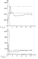
- the breakout force reaches 6000 N and falls steeply and after about 1mm of travel, immediately clear it off, to later on low level with breakaway elements with inclined surfaces below 2000 N uniformly over the entire length of 45 mm remain.
- the inventive arrangement is so defines the absorption energy after the short break-off process, reproducible and specifiable by the absorption element as preferably a tear tab determines, for example with energy absorption forces from 1200 to 5500 N is specified.
- a breakaway element to realize is to if, for example, between the sliding surfaces 8, 12 surveys 26, 27 are arranged to the sliding surfaces in the Starting position at a small distance of a few tenths mm to hold about 3mm.
- the elevations 26, 27 are on both sides of the sliding surfaces substantially symmetrically so to arrange that where the elevations are clamped together lie on top of each other, short sliding surfaces 12 arise, which in case of displacement, ie in the event of a crash, slide down from each other and so on a short distance in the mm range the Clamp the clamping force effect, which then the energy absorption is taken over defined by the absorption element 7, 9, 10, 11.
- Such surveys can be formed, for example, knob-like be and both sides in Wellenachsenl Kunststoffsraum the screw fastening 17 are arranged. But it can also several knob-like elevations next to each other or behind each other and further stepped or even on a crooked Level lying, depending on the requirement of the Clamping forces, frictional forces and displacement paths respectively the dimensioning of the entire arrangement. in the In the present case, the sliding block 13, for example, as realized simple washer. But it is also possible These knob-like formations in the area of the shoe 13 to provide.
- Figure 7 is another extremely advantageous and simple to be realized execution of a breakaway element shown.
- the aneinaderophil, clamped surfaces of the shoe 13 and the original Wedge shoe 14 is not wedge-shaped, but formed like a staircase.
- the step width of the staircase-like Training here defines the Losbrechweg.
Landscapes
- Engineering & Computer Science (AREA)
- Chemical & Material Sciences (AREA)
- Combustion & Propulsion (AREA)
- Transportation (AREA)
- Mechanical Engineering (AREA)
- Steering Controls (AREA)
Applications Claiming Priority (3)
| Application Number | Priority Date | Filing Date | Title |
|---|---|---|---|
| CH112798 | 1998-05-22 | ||
| CH112798 | 1998-05-22 | ||
| PCT/CH1999/000215 WO1999061299A1 (de) | 1998-05-22 | 1999-05-20 | Crashsystem für lenksäule |
Publications (2)
| Publication Number | Publication Date |
|---|---|
| EP1080003A1 EP1080003A1 (de) | 2001-03-07 |
| EP1080003B1 true EP1080003B1 (de) | 2003-04-09 |
Family
ID=4203127
Family Applications (1)
| Application Number | Title | Priority Date | Filing Date |
|---|---|---|---|
| EP99919021A Expired - Lifetime EP1080003B1 (de) | 1998-05-22 | 1999-05-20 | Crashsystem für lenksäule |
Country Status (7)
| Country | Link |
|---|---|
| US (1) | US6505856B1 (enExample) |
| EP (1) | EP1080003B1 (enExample) |
| JP (1) | JP4387592B2 (enExample) |
| CN (1) | CN1107608C (enExample) |
| DE (1) | DE59904962D1 (enExample) |
| ES (1) | ES2192048T3 (enExample) |
| WO (1) | WO1999061299A1 (enExample) |
Families Citing this family (11)
| Publication number | Priority date | Publication date | Assignee | Title |
|---|---|---|---|---|
| FR2802884B1 (fr) * | 1999-12-22 | 2002-05-03 | Ecia Equip Composants Ind Auto | Ensemble de colonne de direction retractable en cas de choc |
| JP4667676B2 (ja) * | 2000-09-19 | 2011-04-13 | エヌエスケー ステアリング システムズ ヨーロッパ リミテッド | 車両のステアリングコラム制御装置 |
| CA2383291A1 (fr) * | 2002-05-08 | 2003-11-08 | Michel Jauvin | Kit d'articles de sport |
| JP4126955B2 (ja) * | 2002-05-08 | 2008-07-30 | 日本精工株式会社 | 衝撃吸収式ステアリングコラム装置 |
| JPWO2004005109A1 (ja) * | 2002-07-02 | 2005-11-04 | 日本精工株式会社 | 車両用衝撃吸収式ステアリングコラム装置 |
| KR100836909B1 (ko) * | 2006-07-12 | 2008-06-11 | 현대자동차주식회사 | 차량용 스티어링 컬럼의 충격 흡수 시스템 |
| CA2800564A1 (en) | 2010-05-28 | 2011-12-01 | Mead Products Llc | Bound edge tabs for notebook |
| JP5499995B2 (ja) * | 2010-08-26 | 2014-05-21 | 日本精工株式会社 | 電動式パワーステアリング装置を備えた衝撃吸収式ステアリング装置 |
| CN102145704B (zh) * | 2011-03-15 | 2012-07-18 | 四川绵阳三力股份有限公司 | 转向柱碰撞溃缩保护机构 |
| DE102015219086B3 (de) | 2015-10-02 | 2017-03-16 | Thyssenkrupp Ag | Energieabsorptionselement für eine Lenksäule eines Kraftfahrzeugs und Lenksäule für ein Kraftfahrzeug |
| CN107672536A (zh) * | 2017-10-12 | 2018-02-09 | 惠州市华阳多媒体电子有限公司 | 一种车载屏幕溃缩结构 |
Family Cites Families (6)
| Publication number | Priority date | Publication date | Assignee | Title |
|---|---|---|---|---|
| ES2033984T3 (es) * | 1987-06-19 | 1993-04-01 | Dr.Ing.H.C. F. Porsche Aktiengesellschaft | Fijacion de columna de direccion para un automovil con un elemento de deformacion. |
| JPH0282670U (enExample) * | 1988-12-16 | 1990-06-26 | ||
| US5390955A (en) * | 1993-12-23 | 1995-02-21 | Chrysler Corporation | Steering column release capsules |
| DE19637175C2 (de) * | 1995-09-13 | 2001-12-06 | Aisin Seiki | Vorrichtung zum Schneiden eines gekrümmten, kontinuierlich zugeführten Werkstücks |
| JPH0976923A (ja) * | 1995-09-13 | 1997-03-25 | Aisin Seiki Co Ltd | 車両用ステアリング装置 |
| SE507771C2 (sv) * | 1996-11-21 | 1998-07-13 | Volvo Ab | Anordning och förfarande för skydd av åkande i fordon |
-
1999
- 1999-05-20 JP JP2000550723A patent/JP4387592B2/ja not_active Expired - Fee Related
- 1999-05-20 DE DE59904962T patent/DE59904962D1/de not_active Expired - Lifetime
- 1999-05-20 ES ES99919021T patent/ES2192048T3/es not_active Expired - Lifetime
- 1999-05-20 US US09/700,377 patent/US6505856B1/en not_active Expired - Lifetime
- 1999-05-20 WO PCT/CH1999/000215 patent/WO1999061299A1/de not_active Ceased
- 1999-05-20 CN CN99806183A patent/CN1107608C/zh not_active Expired - Fee Related
- 1999-05-20 EP EP99919021A patent/EP1080003B1/de not_active Expired - Lifetime
Also Published As
| Publication number | Publication date |
|---|---|
| JP2002516219A (ja) | 2002-06-04 |
| ES2192048T3 (es) | 2003-09-16 |
| US6505856B1 (en) | 2003-01-14 |
| EP1080003A1 (de) | 2001-03-07 |
| JP4387592B2 (ja) | 2009-12-16 |
| CN1107608C (zh) | 2003-05-07 |
| WO1999061299A1 (de) | 1999-12-02 |
| CN1301223A (zh) | 2001-06-27 |
| DE59904962D1 (de) | 2003-05-15 |
Similar Documents
| Publication | Publication Date | Title |
|---|---|---|
| EP2013067B1 (de) | Lenksäule für ein kraftfahrzeug | |
| EP1245456B1 (de) | Aufpralldämpfer | |
| DE2535812C2 (de) | Sicherheitslenksäule für Kraftfahrzeuge | |
| EP1802510B1 (de) | Verstellbare lenksäule eines kraftfahrzeuges | |
| EP1077861B1 (de) | Crashsystem für lenksäule | |
| EP0245612A2 (de) | Lenksäulenbefestigung für ein Kraftfahrzeug | |
| AU9711498A (en) | Highway barrier and guardrail | |
| EP3529129B1 (de) | Lenksäule mit energieabsorptionsvorrichtung für ein kraftfahrzeug | |
| EP1080003B1 (de) | Crashsystem für lenksäule | |
| EP1493634B1 (de) | Airbagmodul mit Gehäuse für die Aufnahme mindestens eines Gasgenerators und mindestens eines Gassacks | |
| EP3356202B1 (de) | Energieabsorptionselement für eine lenksäule eines kraftfahrzeugs und lenksäule für ein kraftfahrzeug | |
| EP1762660B1 (de) | Verkehrs-Leit-Einrichtung | |
| WO2007101565A1 (de) | Lenksäulenanordnung für fahrzeuge | |
| EP0537454A1 (de) | Sicherheitsvorrichtung | |
| EP2207708B1 (de) | Lenksäule für ein kraftfahrzeug | |
| DE19515009A1 (de) | Energieabsorptionsplatte für eine stoßabsorbierende Lenkeinrichtung | |
| DE10039792A1 (de) | Lenksäule für ein Kraftfahrzeug | |
| DE19711392C1 (de) | Lenksäule und Sicherheitsgurte eines Fahrzeuges mit Schutzvorrichtung | |
| EP1077862B1 (de) | Crashsystem für lenksäule | |
| DE69115609T2 (de) | Lenksäule versehen mit einem energieabsorbierenden System | |
| DE19829566A1 (de) | Aufpralldämpfer für Kraftfahrzeuge | |
| DE10313470B3 (de) | Lenksäulenanordnung für ein Kraftfahrzeug | |
| DE102009008838B4 (de) | Lenksäule für ein Kraftfahrzeug | |
| EP0737781B1 (de) | Vorrichtung zum Verbinden von Dämpfelementen | |
| DE19706609C5 (de) | Vorrichtung zur Befestigung des Lenkrads in einem Kraftfahrzeug |
Legal Events
| Date | Code | Title | Description |
|---|---|---|---|
| PUAI | Public reference made under article 153(3) epc to a published international application that has entered the european phase |
Free format text: ORIGINAL CODE: 0009012 |
|
| 17P | Request for examination filed |
Effective date: 20001222 |
|
| AK | Designated contracting states |
Kind code of ref document: A1 Designated state(s): CH DE ES FR GB IT LI |
|
| 17Q | First examination report despatched |
Effective date: 20010307 |
|
| GRAG | Despatch of communication of intention to grant |
Free format text: ORIGINAL CODE: EPIDOS AGRA |
|
| GRAG | Despatch of communication of intention to grant |
Free format text: ORIGINAL CODE: EPIDOS AGRA |
|
| GRAH | Despatch of communication of intention to grant a patent |
Free format text: ORIGINAL CODE: EPIDOS IGRA |
|
| RAP1 | Party data changed (applicant data changed or rights of an application transferred) |
Owner name: THYSSENKRUPP PRESTA AG |
|
| GRAH | Despatch of communication of intention to grant a patent |
Free format text: ORIGINAL CODE: EPIDOS IGRA |
|
| GRAA | (expected) grant |
Free format text: ORIGINAL CODE: 0009210 |
|
| AK | Designated contracting states |
Designated state(s): CH DE ES FR GB IT LI |
|
| REG | Reference to a national code |
Ref country code: GB Ref legal event code: FG4D Free format text: NOT ENGLISH |
|
| REG | Reference to a national code |
Ref country code: CH Ref legal event code: EP |
|
| PG25 | Lapsed in a contracting state [announced via postgrant information from national office to epo] |
Ref country code: LI Free format text: LAPSE BECAUSE OF NON-PAYMENT OF DUE FEES Effective date: 20030531 Ref country code: CH Free format text: LAPSE BECAUSE OF NON-PAYMENT OF DUE FEES Effective date: 20030531 |
|
| GBT | Gb: translation of ep patent filed (gb section 77(6)(a)/1977) | ||
| REG | Reference to a national code |
Ref country code: ES Ref legal event code: FG2A Ref document number: 2192048 Country of ref document: ES Kind code of ref document: T3 |
|
| ET | Fr: translation filed | ||
| REG | Reference to a national code |
Ref country code: CH Ref legal event code: PL |
|
| PLBE | No opposition filed within time limit |
Free format text: ORIGINAL CODE: 0009261 |
|
| STAA | Information on the status of an ep patent application or granted ep patent |
Free format text: STATUS: NO OPPOSITION FILED WITHIN TIME LIMIT |
|
| 26N | No opposition filed |
Effective date: 20040112 |
|
| PGFP | Annual fee paid to national office [announced via postgrant information from national office to epo] |
Ref country code: IT Payment date: 20120523 Year of fee payment: 14 |
|
| PG25 | Lapsed in a contracting state [announced via postgrant information from national office to epo] |
Ref country code: IT Free format text: LAPSE BECAUSE OF NON-PAYMENT OF DUE FEES Effective date: 20130520 |
|
| REG | Reference to a national code |
Ref country code: FR Ref legal event code: PLFP Year of fee payment: 18 |
|
| REG | Reference to a national code |
Ref country code: FR Ref legal event code: PLFP Year of fee payment: 19 |
|
| PGFP | Annual fee paid to national office [announced via postgrant information from national office to epo] |
Ref country code: DE Payment date: 20170523 Year of fee payment: 19 Ref country code: FR Payment date: 20170523 Year of fee payment: 19 Ref country code: GB Payment date: 20170519 Year of fee payment: 19 |
|
| PGFP | Annual fee paid to national office [announced via postgrant information from national office to epo] |
Ref country code: ES Payment date: 20170627 Year of fee payment: 19 |
|
| REG | Reference to a national code |
Ref country code: DE Ref legal event code: R119 Ref document number: 59904962 Country of ref document: DE |
|
| GBPC | Gb: european patent ceased through non-payment of renewal fee |
Effective date: 20180520 |
|
| PG25 | Lapsed in a contracting state [announced via postgrant information from national office to epo] |
Ref country code: DE Free format text: LAPSE BECAUSE OF NON-PAYMENT OF DUE FEES Effective date: 20181201 Ref country code: FR Free format text: LAPSE BECAUSE OF NON-PAYMENT OF DUE FEES Effective date: 20180531 Ref country code: GB Free format text: LAPSE BECAUSE OF NON-PAYMENT OF DUE FEES Effective date: 20180520 |
|
| REG | Reference to a national code |
Ref country code: ES Ref legal event code: FD2A Effective date: 20190913 |
|
| PG25 | Lapsed in a contracting state [announced via postgrant information from national office to epo] |
Ref country code: ES Free format text: LAPSE BECAUSE OF NON-PAYMENT OF DUE FEES Effective date: 20180521 |