EP1079507A1 - Regulateur de commutation, convertisseur cc/cc et systeme lsi comprenant un tel regulateur - Google Patents
Regulateur de commutation, convertisseur cc/cc et systeme lsi comprenant un tel regulateur Download PDFInfo
- Publication number
- EP1079507A1 EP1079507A1 EP00905274A EP00905274A EP1079507A1 EP 1079507 A1 EP1079507 A1 EP 1079507A1 EP 00905274 A EP00905274 A EP 00905274A EP 00905274 A EP00905274 A EP 00905274A EP 1079507 A1 EP1079507 A1 EP 1079507A1
- Authority
- EP
- European Patent Office
- Prior art keywords
- switch
- potential
- switching regulator
- period
- output node
- Prior art date
- Legal status (The legal status is an assumption and is not a legal conclusion. Google has not performed a legal analysis and makes no representation as to the accuracy of the status listed.)
- Withdrawn
Links
Images


Classifications
-
- H—ELECTRICITY
- H02—GENERATION; CONVERSION OR DISTRIBUTION OF ELECTRIC POWER
- H02M—APPARATUS FOR CONVERSION BETWEEN AC AND AC, BETWEEN AC AND DC, OR BETWEEN DC AND DC, AND FOR USE WITH MAINS OR SIMILAR POWER SUPPLY SYSTEMS; CONVERSION OF DC OR AC INPUT POWER INTO SURGE OUTPUT POWER; CONTROL OR REGULATION THEREOF
- H02M3/00—Conversion of dc power input into dc power output
- H02M3/02—Conversion of dc power input into dc power output without intermediate conversion into ac
- H02M3/04—Conversion of dc power input into dc power output without intermediate conversion into ac by static converters
- H02M3/10—Conversion of dc power input into dc power output without intermediate conversion into ac by static converters using discharge tubes with control electrode or semiconductor devices with control electrode
- H02M3/145—Conversion of dc power input into dc power output without intermediate conversion into ac by static converters using discharge tubes with control electrode or semiconductor devices with control electrode using devices of a triode or transistor type requiring continuous application of a control signal
- H02M3/155—Conversion of dc power input into dc power output without intermediate conversion into ac by static converters using discharge tubes with control electrode or semiconductor devices with control electrode using devices of a triode or transistor type requiring continuous application of a control signal using semiconductor devices only
-
- H—ELECTRICITY
- H02—GENERATION; CONVERSION OR DISTRIBUTION OF ELECTRIC POWER
- H02M—APPARATUS FOR CONVERSION BETWEEN AC AND AC, BETWEEN AC AND DC, OR BETWEEN DC AND DC, AND FOR USE WITH MAINS OR SIMILAR POWER SUPPLY SYSTEMS; CONVERSION OF DC OR AC INPUT POWER INTO SURGE OUTPUT POWER; CONTROL OR REGULATION THEREOF
- H02M1/00—Details of apparatus for conversion
- H02M1/36—Means for starting or stopping converters
-
- H—ELECTRICITY
- H02—GENERATION; CONVERSION OR DISTRIBUTION OF ELECTRIC POWER
- H02M—APPARATUS FOR CONVERSION BETWEEN AC AND AC, BETWEEN AC AND DC, OR BETWEEN DC AND DC, AND FOR USE WITH MAINS OR SIMILAR POWER SUPPLY SYSTEMS; CONVERSION OF DC OR AC INPUT POWER INTO SURGE OUTPUT POWER; CONTROL OR REGULATION THEREOF
- H02M1/00—Details of apparatus for conversion
- H02M1/32—Means for protecting converters other than automatic disconnection
-
- H—ELECTRICITY
- H02—GENERATION; CONVERSION OR DISTRIBUTION OF ELECTRIC POWER
- H02M—APPARATUS FOR CONVERSION BETWEEN AC AND AC, BETWEEN AC AND DC, OR BETWEEN DC AND DC, AND FOR USE WITH MAINS OR SIMILAR POWER SUPPLY SYSTEMS; CONVERSION OF DC OR AC INPUT POWER INTO SURGE OUTPUT POWER; CONTROL OR REGULATION THEREOF
- H02M3/00—Conversion of dc power input into dc power output
- H02M3/02—Conversion of dc power input into dc power output without intermediate conversion into ac
- H02M3/04—Conversion of dc power input into dc power output without intermediate conversion into ac by static converters
- H02M3/10—Conversion of dc power input into dc power output without intermediate conversion into ac by static converters using discharge tubes with control electrode or semiconductor devices with control electrode
- H02M3/145—Conversion of dc power input into dc power output without intermediate conversion into ac by static converters using discharge tubes with control electrode or semiconductor devices with control electrode using devices of a triode or transistor type requiring continuous application of a control signal
- H02M3/155—Conversion of dc power input into dc power output without intermediate conversion into ac by static converters using discharge tubes with control electrode or semiconductor devices with control electrode using devices of a triode or transistor type requiring continuous application of a control signal using semiconductor devices only
- H02M3/156—Conversion of dc power input into dc power output without intermediate conversion into ac by static converters using discharge tubes with control electrode or semiconductor devices with control electrode using devices of a triode or transistor type requiring continuous application of a control signal using semiconductor devices only with automatic control of output voltage or current, e.g. switching regulators
- H02M3/158—Conversion of dc power input into dc power output without intermediate conversion into ac by static converters using discharge tubes with control electrode or semiconductor devices with control electrode using devices of a triode or transistor type requiring continuous application of a control signal using semiconductor devices only with automatic control of output voltage or current, e.g. switching regulators including plural semiconductor devices as final control devices for a single load
- H02M3/1588—Conversion of dc power input into dc power output without intermediate conversion into ac by static converters using discharge tubes with control electrode or semiconductor devices with control electrode using devices of a triode or transistor type requiring continuous application of a control signal using semiconductor devices only with automatic control of output voltage or current, e.g. switching regulators including plural semiconductor devices as final control devices for a single load comprising at least one synchronous rectifier element
-
- H—ELECTRICITY
- H02—GENERATION; CONVERSION OR DISTRIBUTION OF ELECTRIC POWER
- H02M—APPARATUS FOR CONVERSION BETWEEN AC AND AC, BETWEEN AC AND DC, OR BETWEEN DC AND DC, AND FOR USE WITH MAINS OR SIMILAR POWER SUPPLY SYSTEMS; CONVERSION OF DC OR AC INPUT POWER INTO SURGE OUTPUT POWER; CONTROL OR REGULATION THEREOF
- H02M1/00—Details of apparatus for conversion
- H02M1/0003—Details of control, feedback or regulation circuits
- H02M1/0009—Devices or circuits for detecting current in a converter
-
- Y—GENERAL TAGGING OF NEW TECHNOLOGICAL DEVELOPMENTS; GENERAL TAGGING OF CROSS-SECTIONAL TECHNOLOGIES SPANNING OVER SEVERAL SECTIONS OF THE IPC; TECHNICAL SUBJECTS COVERED BY FORMER USPC CROSS-REFERENCE ART COLLECTIONS [XRACs] AND DIGESTS
- Y02—TECHNOLOGIES OR APPLICATIONS FOR MITIGATION OR ADAPTATION AGAINST CLIMATE CHANGE
- Y02B—CLIMATE CHANGE MITIGATION TECHNOLOGIES RELATED TO BUILDINGS, e.g. HOUSING, HOUSE APPLIANCES OR RELATED END-USER APPLICATIONS
- Y02B70/00—Technologies for an efficient end-user side electric power management and consumption
- Y02B70/10—Technologies improving the efficiency by using switched-mode power supplies [SMPS], i.e. efficient power electronics conversion e.g. power factor correction or reduction of losses in power supplies or efficient standby modes
Definitions
- the present invention relates to a technique in a switching regulator to detect and restrain inrush current at turn-on or in the initial operation, or excessive current caused at a short-circuit failure in the capacity for smoothing the output voltage.
- the inrush current refers to the current that flows abruptly to charge the capacity for smoothing the output voltage when a switch connected to the power source is turned on in the initial operation such as at power-on.
- the excessive current refers to the current that flows excessively from the power source towards the load when the switch connected to the power source is in the ON state. Without restraining the inrush current and the excessive current, the current flowing through the inductor within the smoothing circuit would exceed the maximum rating value, thereby causing the deterioration of the performance or even a breakage. It must be noted that in the present specification the inrush current and the excessive current are collectively called inrush current except for the case where it might be misleading.
- an inrush current detection circuit 50 includes a resistance element 51 for inrush current detection and an inrush current detector 52 which detects the presence or absence of the inrush current by means of the voltage across the resistance element 51 .
- the inrush current detector 52 places the switching element 53 with a small on resistance in the ON state in a steady operation, and turns the element 53 off to flow the current to a resistance element 54 for inrush current restraint upon the inrush current detection.
- the resistance element 54 for inrush current restraint is composed of a resistor with a large resistance value or a temperature fuse resistor which interrupts a current flow in response to overheating (Refer to Japanese Laid-Open Patent Application No. 9-121546).
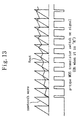
- Figure 12 shows another example of the circuit structure of the conventional switching regulator, which controls the switching pulse width variably with a sawtooth wave in the initial operation.
- a selector 56 selects and outputs the sawtooth wave in the initial operation and a reference potential in the steady operation. Consequently, as shown in Figure 13 , early in the initial operation, the on signal of the p-type MOS transistor switch SW1 has a short pulse width due to the comparison between the sawtooth wave and the output voltage Vout, and later the pulse width becomes gradually longer with increasing output voltage Vout. As a result, the inrush current in the initial operation is successfully restrained.
- Figure 14 shows a further another example of the circuit structure of the switching regulator which restrains the inrush current in the initial operation by means of a sawtooth wave in the same manner as in Figure 12 .
- the on-off control of switching elements 61 , 62 are done by using a loop 1 in the initial operation and a loop 2 in the steady operation.
- a sawtooth wave generating circuit 63 generates a sawtooth wave STW so as to perform the initializing operation while gradually changing the switching on-off duty, thereby restraining the inrush current in the initial operation (Refer to Japanese Laid-Open Application No. 5-56636).
- the structure with the inrush current restraint circuit shown in Figure 11 has a drawback of a low power conversion efficiency.
- the resistance element 51 for inrush current detection causes a resistance loss because it is interposed with a current path from the power source, and therefore, the power conversion efficiency of the switching regulator deteriorates.
- the present invention has an object of providing a switching regulator which restrains the inrush current and the excessive current while maintaining a high power conversion efficiency and which requires a shorter time for initialization than conventional switching regulators.
- a switching regulator of a synchronous rectifying mode of the present invention comprises: a first switch and a second switch arranged in series between a first power source which supplies a first potential and a second power source which supplies a second potential lower than the first potential, the first switch being positioned closer to the first power source than the second switch; a switch control unit for controlling an on-off operation of the first and second switches; and a smoothing circuit for smoothing a potential of an output node between the first switch and the second switch, said switch control unit turning off the first switch when the potential of said output node is below a first reference potential which becomes a reference to detect an occurrence of inrush current or excessive current while the first switch is in an ON state.
- the first switch when the potential of the output node goes below the first reference potential while the first switch is in the ON state, the first switch is turned off by regarding it as the occurrence of the inrush current or the excessive current.
- the first switch when the occurrence of the inrush current and the excessive current has been detected by making use of a voltage drop due to the on resistance of the first switch, the first switch is turned off so as to interrupt the inrush or excessive current.
- This approach can realize the detection of the inrush or excessive current without setting up a resistance element for detection or without causing a decrease in the power conversion efficiency of the switching regulator.
- the initial operation does not need a different control from the steady operation, which makes it possible to restrain the inrush current in the initial operation and the excessive current in the steady operation in the same manner.
- the switch control unit of the switching regulator of the present invention preferably comprises: a first reference potential generating circuit for generating the first reference potential; a first potential comparator for comparing the first reference potential generated by the first reference potential generating circuit with the potential of said output node; and an available period setting circuit for setting an available period during which the comparison results of the first potential comparator is valid.
- the switch control unit turns off the first switch when the first potential comparator detects that the potential of said output node is below the first reference potential during said available period set by said available period setting circuit.
- the available period setting circuit sets the start of said available period at a time when a predetermined time period has elapsed since the first switch is turned on.
- said switch control unit places the second switch in the ON state for a predetermined time period before the first switch is turned back on.
- the second switch can be placed in the ON state for a predetermined time period to flow a current from the second power source towards the smoothing circuit. Therefore, in the initial operation, the time required to boost the output voltage of the smoothing circuit to a preset voltage or the time required for initialization can be accelerated.
- the predetermined time period is preferably set at a fixed time period.
- the predetermined time period is preferably set variable in accordance with an output voltage of said smoothing circuit.
- the switch control unit turns off the second switch when the potential of said output node exceeds a second reference potential which becomes the reference to determine the termination of the ON-time-period of the second switch while the second switch is in the ON state.
- the LSI system of the present invention comprises: said switching regulator of claim 1 and an LSI core unit driven by a voltage supplied from said switching regulator.
- the DC/DC converter of the present invention comprises: a first switch and a second switch arranged in series between a first power source which supplies a first potential and a second power source which supplies a second potential lower than the first potential, the first switch being positioned closer to the first power source than the second switch; and a switch control unit for controlling the on-off operation of the first and second switches.
- the switch control unit turns off the first switch when the potential of said output node is below a first reference potential which becomes the reference to detect the occurrence of inrush current or excessive current while the first switch is in the ON state.
- FIG. 1 shows the structure of the switching regulator of the embodiment of the present invention.
- the switching regulator comprises a first switch SW1 composed of a p-type MOS transistor and a second switch SW2 composed of an n-type MOS transistor which are arranged in series between a first power source (hereinafter referred to as power source Vdd) to supply power-supply voltage Vdd as the first potential and a second power source (hereinafter referred to as power source Vss) to supply a ground potential Vss as the second potential, a diode 3 which flows a current from the power source Vss when the first and second switches SW1, SW2 are both in the OFF state, and a smoothing circuit 4 which smoothes the potential Vnd of the output node between the first and second switches SW1 and SW2.
- the smoothing circuit 4 is composed of an inductor 5 and a capacity 6 for smoothing output voltage, and smoothes the potential Vnd which has shaped a rectangular wave as a result of the switching operation of the first and second switches SW1, SW2 into a constant voltage.
- the voltage smoothed by the smoothing circuit 4 is supplied to an output load 7 as the output voltage Vout.
- the switching regulator further comprises a control circuit 10 which controls the switching operation of the first and second switches SW1 and SW2 using a first and second switching signals Sp and Sn, a first reference potential generating circuit 11 which generates a first reference potential Vr1 as the reference to detect inrush current, and a first potential comparator 12 which compares the first reference potential Vr1 generated by the first reference potential generating circuit 11 with the output node potential Vnd.
- the control circuit 10 , the first reference potential generating circuit 11 and the first potential comparator 12 compose a switch control unit 1 .
- the first and second switches SW1 and SW2, the switch control unit 1 , the diode 3 and the smoothing circuit 4 compose the switching regulator of the present embodiment.
- the feature of the present embodiment is to detect the presence or absence of the occurrence of inrush current by making use of a voltage drop due to the on resistance of the first switch SW1.
- the control circuit 10 basically controls the switching operation of the first and second switches SW1, SW2 based on a control signal Sdt indicating the results of the comparison between the output voltage Vout and a reference voltage Vref generated by a reference voltage generating circuit 9 , and further controls inrush current restraint based on a first determination signal Sc1 outputted from the first potential comparator 12 .
- the control circuit 10 makes the first switching signal Sp a low ("L") to turn on the first switch SW1 (A in Figure 2 ), and as a result, a current flows from the power source Vdd towards the smoothing circuit 4 so as to start charging the capacity 6 .
- inrush current occurs (B in Figure 2 ).
- I represents the current value of the inrush current.
- the control circuit 10 When the first determination signal Sc1 indicates that the output node potential Vnd goes below the first reference potential Vr1, or that the signal Sc1 becomes a high ("H") within a set available period (which will be detailed later), the control circuit 10 forcibly turns off the first switch SW1 on the assumption that the inrush current has exceeded the set limit.
- the control circuit 10 places the second switch SW2 in the ON state for a predetermined time period (E in Figure 2 ). As a result, the current IL flows less and less through the inductor 5 . After turning off the second switch SW2, the control circuit 10 turns the first switch SW1 back on (F In Figure 2 ). At this time, in the same manner as above, when the first determination signal.
- the initializing operation can be performed with restrained inrush current.
- the control circuit 10 behaves as follows.
- the control signal Sdt indicating the results of the comparison between the output voltage Vout and the reference voltage Vref is fed back to the control circuit 10 where the first switch SW1 and the second switch SW2 are alternately turned on and off based on a PWM control system. Consequently, the output voltage Vout is kept constant.
- the control circuit 10 turns off the first switch SW1 to restrain excessive current.
- the inrush current can be detected and restrained without providing a resistance element, thereby making it possible to maintain high power conversion efficiency.
- Figures 3 (a) and 3 (b) are graphs showing the time-varying inductor current IL in the initial operation:
- Figure 3 (a) shows the present embodiment and
- Figure 3 (b) shows the conventional structures with the sawtooth wave as shown in Figures 12 and 14 .
- the initial operation can be performed while flowing the current IL through the inductor 5 nearly at the set upper limit value.
- the time required for the initialization which is the time necessary to supply the amount of charge (corresponding to the diagonally shaded area in Figure 3 ) to the capacity 6 for smoothing output voltage, can be greatly reduced in the present embodiment as is shown in Figure 3 .
- FIG 4 shows the internal structure of the control circuit 10 .
- the control circuit 10 comprises an available period setting circuit 21 which sets the available period of the first determination signal Sc1 and an ON-time-period setting circuit 23 which sets the ON-time-period of the second switch SW2.
- the control circuit 10 controls the switching operation of the first and second switches SW1 and SW2 according to the control signal Sdt.
- An available period signal Sv1 outputted from the available period setting circuit 21 becomes “H” only when the inputs of a NOR gate 21a are all lows.
- the available period signal Sv1 becomes “H” by lagging only behind a signal propagation time of the inverter 21b after the first switching signal Sp becomes “L”, and becomes “L” when the first switching signal Sp becomes “H”.
- the available period is when the available period signal Sv1 is "H”.
- the control signal Sc1 becomes “H” while the signal Sv1 is "H”
- the output of the AND gate 22 becomes “H”.
- the ON-time-period setting circuit 23 makes its output “H” for the time period set by the counter 25 .
- the output signal of the OR gate 26 becomes “H” for a fixed time period, thereby placing the second switch SW2 in the ON state for the fixed time period.
- Figure 5 shows the behavior of the switching regulator of Figure 1 and explains the setting of the available period during which the first determination signal Sc1 is valid.
- (1) and (2) indicate the voltage and signal waveforms when inrush current occurs, while (3) indicates the voltage and signal waveforms when no inrush current occurs.
- the control circuit 10 makes the first switching signal Sp "L” to place the first switch SW1 in the ON state (H in Figure 5 ). Consequently, the output node potential Vnd grows to reach the power-supply potential Vdd, during which the potential Vnd exceeds the first reference potential Vr1 (I in Figure 5 ) to make the first determination signal Sc1 "L".
- the delay signal Sp-delay of the first switching signal Sp becomes "L” by lagging only behind the signal propagation time of the two inverters 21b (J in Figure 5 ).
- the available period signal Sve becomes "H” with a delay time corresponding to the signal propagation time of the two inverters 21b after the first switching signal Sp becomes “L".
- the time required for the output node potential Vnd to exceed the first reference potential Vr1 depends on the load current value, or the charge status of the capacity 6 , that is, the output voltage Vout. Therefore, the delay time of the available period signal Sve must be set long enough to secure that the output node potential Vnd exceeds the first reference potential Vr1 by the start of the available period.
- the case of (2) will be described as follows.
- the control circuit 10 makes the first switching signal Sp "L” to turn on the first switch SW1 (O in Figure 5 ). Consequently, the output node potential Vnd increases; however, when the inrush or excessive current is already flowing, the output node potential Vnd does not reach the first reference potential Vr1 (P in Figure 5 ). At this time, the control circuit 10 immediately turns off the first switch SW1 because the first determination signal Sc1 remains to be "H” (R in Figure 5 ) when the available period signal Sve becomes "H” (Q in Figure 5 ).
- the first switch SW1 Since the first switch SW1 is in the ON state only during the signal propagation time of the two inverters 21b after the first switching signal Sp becomes "L", the first reference potential Vr1 must be set with some margins by taking the inrush current which flows during this time period into account.
- the control circuit 10 makes the first switching signal Sp "H” in accordance with the control signal Sdt to turn off the first switch SW1 (W in Figure 5 ). Accordingly, the available period signal Sve also becomes “L” immediately. Later, even when the first determination signal Sc1 becomes “H” (X in Figure 5 ), the switching regulator can continue the steady operation because the available period signal Sve is "L".
- the ON-time-period of the second switch SW2 is a very important factor to the time required for the initialization and to the efficiency.
- the ON-time-period of the second switch SW2 is set as follows.
- the rate of decrease in the current IL flowing through the inductor 5 in the ON-time-period of the second switch SW2 depends on the voltage across the inductor 5 or the difference between the output node potential Vnd and the output voltage Vout (approximately corresponding to the output voltage Vout).
- the output voltage Vout is low, a certain time period during which the current IL flowing through the inductor 5 fully falls is set as the ON-time-period of the second switch SW2.
- the ON-time-period is set as the time required to sufficiently decrease the amount of the current IL flowing through the inductor 5 to the value which allows the output node potential Vnd to exceed the first reference potential Vr1 when the first switch SW1 is turned back on.
- the ON-time-period of the second switch SW2 can be set to be variable in accordance with the output voltage Vout.
- the rate of decrease in the current IL flowing through the inductor 7 when the second switch SW2 is in the ON state is small when the output voltage Vout is low, and large when it is high. Judging from this, in the initial operation, it is preferable that when the output voltage Vout is low, the ON-time-period of the second switch SW2 should be set long and made gradually shorter with the output voltage Vout increasing.
- the ON-time-period of the second switch SW2 at the beginning of the initial operation can be set in the above-mentioned time period. Setting the ON-time-period of the second switch SW2 variable like this In accordance with the output voltage Vout achieves the reduction of the time required for the initialization.
- FIG. 6 shows the circuit structure of the ON-time-period setting circuit to realize the above-mentioned control.
- the ON-time-period setting circuit 23A shown in Figure 6 comprises four counters 25a to 25d to which four different ON-time-periods such as 4 ⁇ s, 3 ⁇ s, 2 ⁇ s and 1 ⁇ s can be set respectively.
- the values of signals A and B can be set as shown in Table 1 below according to the output voltage Vout.
- Vout A B ON-time-period 0 ⁇ 500 mV L L 4 ⁇ S 500 ⁇ 1 V H L 3 ⁇ S 1V ⁇ 2 V L H 2 ⁇ S 2 V ⁇ H H 1 ⁇ s
- FIG. 7 shows the circuit structure of a modified example of the switching regulator of the present embodiment.
- the switching regulator comprises a second reference potential generating circuit 13 which generates a second reference potential Vr2 as the reference to determine the termination of the ON-time-period of the second switch SW2 and a second potential comparator circuit 14 which compares the output node potential Vnd with the second reference potential Vr2.
- a switch control unit 2 is composed of a control circuit 10A , the first and second reference potential generating circuits 11 , 13 and the first and second potential comparator circuits 12 , 14 .
- the feature of the modified example is to place the second switch SW2 in the ON state until the output node potential Vnd reaches the second reference potential Vr2, instead of previously setting the ON-time-period of the second switch SW2 at a predetermined time period.
- the control circuit 10A basically controls the switching operation of the first and second switches SW1 and SW2, based on the control signal Sdt indicating the results of the comparison between the output voltage Vout and the reference voltage Vref generated by the reference voltage generating circuit 9 .
- the control circuit 10A further controls the restraint of the inrush current based on the first determination signal Sc1 outputted from the first potential comparator 12 and sets the termination of the ON-time-period of the second switch SW2 based on the second determination signal Sc2 outputted from the second potential comparator 14 .
- the ON-time-period of the second switch SW2 is as long as possible within a range where the output node potential Vnd does not exceed the ground potential Vss. Therefore, as in this modified example, the termination of the ON-time-period of the second switch SW2 can be determined by the comparison between the output node potential Vnd and the second reference potential Vr1 so as to reduce the time required for the initialization, while inrush current being restrained.
- Figure 9 shows the circuit structure of the control circuit 10A of Figure 7 .
- like components are labeled with like reference numerals with respect to Figure 4 showing the circuit structure of the control circuit 10 of Figure 1 .
- the ON-time-period setting circuit 23 of Figure 4 is replaced by a 2-input NAND gate 29 which enters the second determination signal Sc2 and the output signal of the NAND gate 22 .
- the first reference potential Vr1 may be so structured that the setting is changeable. This can extend the range of choices of the inductor 5 in the smoothing circuit 4 and improve the flexibility of design in the system. It is also possible to make the second reference potential Vr2 changeable in setting.
- FIG 10 shows an example of the LSI system provided with the switching regulator of the present invention.
- the LSI 30 comprises an LSI core unit 31 and a DC/DC converter 32 , and further comprises a diode 3 and a smoothing circuit 4 as external components. There are also pads 33a to 33c .
- the DC/DC converter 32 comprises the first and second switches SW1, SW2 and the switch control unit 1 or 2 shown in the above-mentioned embodiment or the modified example.
- the switching regulator of the present invention is composed of the DC/DC converter 32 , the diode 3 and the smoothing circuit 4 .
- the DC/DC converter 32 converts the power-supply potentials Vdd, Vss supplied to the pads 33a , 33b into the voltage Vnd through the behavior of the above-mentioned embodiment or the modified example to output it to the pad 33c .
- the smoothing circuit 4 smoothes the output voltage Vnd of the DC/DC converter 32 and outputs it as the voltage Vout.
- the output voltage Vout of the smoothing circuit 4 is supplied as the internal power-supply voltage of the LSI core unit 31 .
- the occurrence of inrush current is detected by making use of a voltage drop due to the on resistance of the first switch, so that the detection of the inrush current can be realized without providing a resistance element for detection, that is, without causing a decrease in the power conversion efficiency of the switching regulator.
- excessive current in the steady operation can be restrained in the same manner as the inrush current in the initial operation because the initial operation does not need to be controlled differently from in the steady operation.
Priority Applications (1)
| Application Number | Priority Date | Filing Date | Title |
|---|---|---|---|
| EP09161525.2A EP2110935B1 (fr) | 1999-02-23 | 2000-02-23 | Convertisseur CC-CC |
Applications Claiming Priority (3)
| Application Number | Priority Date | Filing Date | Title |
|---|---|---|---|
| JP4415999 | 1999-02-23 | ||
| JP04415999A JP3389524B2 (ja) | 1999-02-23 | 1999-02-23 | スイッチングレギュレータ、dc/dc変換器、およびスイッチングレギュレータを備えたlsiシステム |
| PCT/JP2000/001012 WO2000051226A1 (fr) | 1999-02-23 | 2000-02-23 | Regulateur de commutation, convertisseur cc/cc et systeme lsi comprenant un tel regulateur |
Related Child Applications (1)
| Application Number | Title | Priority Date | Filing Date |
|---|---|---|---|
| EP09161525.2A Division EP2110935B1 (fr) | 1999-02-23 | 2000-02-23 | Convertisseur CC-CC |
Publications (2)
| Publication Number | Publication Date |
|---|---|
| EP1079507A1 true EP1079507A1 (fr) | 2001-02-28 |
| EP1079507A4 EP1079507A4 (fr) | 2008-07-02 |
Family
ID=12683842
Family Applications (2)
| Application Number | Title | Priority Date | Filing Date |
|---|---|---|---|
| EP00905274A Withdrawn EP1079507A4 (fr) | 1999-02-23 | 2000-02-23 | Regulateur de commutation, convertisseur cc/cc et systeme lsi comprenant un tel regulateur |
| EP09161525.2A Expired - Lifetime EP2110935B1 (fr) | 1999-02-23 | 2000-02-23 | Convertisseur CC-CC |
Family Applications After (1)
| Application Number | Title | Priority Date | Filing Date |
|---|---|---|---|
| EP09161525.2A Expired - Lifetime EP2110935B1 (fr) | 1999-02-23 | 2000-02-23 | Convertisseur CC-CC |
Country Status (6)
| Country | Link |
|---|---|
| US (1) | US6307360B1 (fr) |
| EP (2) | EP1079507A4 (fr) |
| JP (1) | JP3389524B2 (fr) |
| KR (1) | KR100588707B1 (fr) |
| CN (1) | CN1198376C (fr) |
| WO (1) | WO2000051226A1 (fr) |
Cited By (7)
| Publication number | Priority date | Publication date | Assignee | Title |
|---|---|---|---|---|
| WO2002063752A2 (fr) | 2001-02-06 | 2002-08-15 | Koninklijke Philips Electronics N.V. | Convertisseur cc-cc synchrone |
| WO2002063770A2 (fr) * | 2001-02-06 | 2002-08-15 | Koninklijke Philips Electronics N.V. | Circuit de commutation tec |
| EP1333562A1 (fr) * | 2002-02-05 | 2003-08-06 | Magnetek S.p.A. | Convertisseur avec un circuit de lecture du courant de sortie |
| EP1608053A1 (fr) * | 2004-06-14 | 2005-12-21 | Dialog Semiconductor GmbH | Circuit analogique de mesure de courant |
| CN100351727C (zh) * | 2001-04-10 | 2007-11-28 | 株式会社理光 | 稳压器 |
| FR2996701A1 (fr) * | 2012-10-05 | 2014-04-11 | Technoboost | Convertisseur courant continu/courant continu reversible |
| EP2582029A3 (fr) * | 2011-10-14 | 2014-08-06 | Samsung Electronics Co., Ltd | Convertisseur découpage avec régulateur en série pour protection contre les transitoires |
Families Citing this family (31)
| Publication number | Priority date | Publication date | Assignee | Title |
|---|---|---|---|---|
| US5481178A (en) * | 1993-03-23 | 1996-01-02 | Linear Technology Corporation | Control circuit and method for maintaining high efficiency over broad current ranges in a switching regulator circuit |
| US6657419B2 (en) * | 2001-11-19 | 2003-12-02 | Solarmate Corporation | Micro-solar insolation circuit |
| US6791306B2 (en) * | 2002-01-29 | 2004-09-14 | Intersil Americas Inc. | Synthetic ripple regulator |
| ITMI20021539A1 (it) * | 2002-07-12 | 2004-01-12 | St Microelectronics Srl | Controllore digitale per convertitori dc-dc a commutazione |
| US7019502B2 (en) * | 2002-09-06 | 2006-03-28 | Intersil America's Inc. | Synchronization of multiphase synthetic ripple voltage regulator |
| DE10339025B4 (de) * | 2002-09-13 | 2013-08-14 | Fuji Electric Co., Ltd. | Stromversorgungssystem |
| ATE354880T1 (de) * | 2003-08-27 | 2007-03-15 | Fraunhofer Ges Forschung | Steuerungsvorrichtung zum steuern eines ladeschalters in einem schaltregler und verfahren zum steuern eines ladeschalters |
| JP4412535B2 (ja) * | 2003-11-14 | 2010-02-10 | セイコーインスツル株式会社 | 同期整流方式スイッチングレギュレータ制御回路及びこれを含む半導体集積回路 |
| US7355830B2 (en) | 2003-11-21 | 2008-04-08 | Matsushita Electric Industrial Co., Ltd. | Overcurrent protection device |
| JP4685009B2 (ja) * | 2004-03-24 | 2011-05-18 | パナソニック株式会社 | Dc−dcコンバータ |
| KR20050116450A (ko) * | 2004-06-07 | 2005-12-13 | 엘지전자 주식회사 | 전원변환장치 및 방법 |
| JP4578889B2 (ja) * | 2004-08-16 | 2010-11-10 | 富士通セミコンダクター株式会社 | 半導体装置 |
| US7145315B2 (en) * | 2004-09-21 | 2006-12-05 | Broadcom Corporation | Over-current detection circuit in a switch regulator |
| US20060132105A1 (en) * | 2004-12-16 | 2006-06-22 | Prasad Atluri R | Controlling inrush current |
| JP4825632B2 (ja) | 2006-09-29 | 2011-11-30 | パナソニック株式会社 | Dc−dcコンバータ |
| TWI325137B (en) * | 2006-12-15 | 2010-05-21 | Realtek Semiconductor Corp | Output signal driving circuit and method thereof |
| US20090033293A1 (en) * | 2007-08-01 | 2009-02-05 | Intersil Americas Inc. | Voltage converter with combined capacitive voltage divider, buck converter and battery charger |
| US8427113B2 (en) * | 2007-08-01 | 2013-04-23 | Intersil Americas LLC | Voltage converter with combined buck converter and capacitive voltage divider |
| US8018212B1 (en) | 2007-08-24 | 2011-09-13 | Intersil Americas Inc. | Buck-boost regulator |
| JP5151332B2 (ja) * | 2007-09-11 | 2013-02-27 | 株式会社リコー | 同期整流型スイッチングレギュレータ |
| US8148967B2 (en) * | 2008-08-05 | 2012-04-03 | Intersil Americas Inc. | PWM clock generation system and method to improve transient response of a voltage regulator |
| CN102160271B (zh) * | 2008-09-22 | 2013-11-20 | 富士通株式会社 | 电源控制电路、电源装置以及电源控制装置的控制方法 |
| CN101997437B (zh) * | 2009-08-13 | 2014-02-19 | 通嘉科技股份有限公司 | 集成电路以及交换式电源供应器的控制方法 |
| JP5639829B2 (ja) * | 2010-09-27 | 2014-12-10 | シャープ株式会社 | Dc−dcコンバーター |
| US8786270B2 (en) | 2010-11-08 | 2014-07-22 | Intersil Americas Inc. | Synthetic ripple regulator with frequency control |
| TWI410642B (zh) * | 2011-03-04 | 2013-10-01 | Realtek Semiconductor Corp | 電感偵測裝置與方法 |
| JP6087632B2 (ja) * | 2012-01-30 | 2017-03-01 | キヤノン株式会社 | 電力供給装置及び記録装置 |
| US8717001B2 (en) * | 2012-07-03 | 2014-05-06 | Infineon Technologies Austria Ag | Inrush current limiting circuit |
| RU2505913C1 (ru) * | 2012-07-16 | 2014-01-27 | Федеральное государственное бюджетное образовательное учреждение высшего профессионального образования "Уфимский государственный авиационный технический университет" | Импульсный регулятор постоянного напряжения |
| JP6291432B2 (ja) * | 2015-02-04 | 2018-03-14 | 矢崎総業株式会社 | 突入電流抑制回路 |
| KR20180065271A (ko) | 2016-12-07 | 2018-06-18 | 이주호 | 스위칭 레귤레이터의 dc/dc 컨버터회로 |
Citations (4)
| Publication number | Priority date | Publication date | Assignee | Title |
|---|---|---|---|---|
| US5625279A (en) * | 1996-03-28 | 1997-04-29 | Hewlett-Packard Company | DC-DC converter with dynamically adjustable characteristics |
| US5723974A (en) * | 1995-11-21 | 1998-03-03 | Elantec Semiconductor, Inc. | Monolithic power converter with a power switch as a current sensing element |
| JPH10174286A (ja) * | 1996-12-10 | 1998-06-26 | Nec Corp | 電池電源制御装置 |
| EP0884746A2 (fr) * | 1997-06-13 | 1998-12-16 | Linear Technology Corporation | Régulateur à commutation synchrone avec chute de tension d'interrupteur pour détection de courant |
Family Cites Families (14)
| Publication number | Priority date | Publication date | Assignee | Title |
|---|---|---|---|---|
| JPS61254069A (ja) | 1985-04-30 | 1986-11-11 | Matsushita Electric Ind Co Ltd | 電源保護装置 |
| JPH07110132B2 (ja) | 1991-08-22 | 1995-11-22 | 日本モトローラ株式会社 | 電圧変換装置 |
| US5481178A (en) * | 1993-03-23 | 1996-01-02 | Linear Technology Corporation | Control circuit and method for maintaining high efficiency over broad current ranges in a switching regulator circuit |
| JP3349781B2 (ja) | 1993-08-30 | 2002-11-25 | 富士通株式会社 | スイッチングレギュレータ電源装置 |
| US5774319A (en) | 1993-10-27 | 1998-06-30 | Square D Company | Energy validation arrangement for a self-powered circuit interrupter |
| US5414341A (en) * | 1993-12-07 | 1995-05-09 | Benchmarq Microelectronics, Inc. | DC-DC converter operable in an asyncronous or syncronous or linear mode |
| US5638264A (en) | 1993-12-27 | 1997-06-10 | Hitachi, Ltd. | Parallelized power supply system providing uninterrupted operation |
| JP3402983B2 (ja) | 1997-01-29 | 2003-05-06 | 三洋電機株式会社 | 電源回路 |
| JP3691635B2 (ja) * | 1997-05-15 | 2005-09-07 | 富士通株式会社 | 電圧制御回路及びdc/dcコンバータ |
| US6160388A (en) * | 1997-12-30 | 2000-12-12 | Texas Instruments Incorporated | Sensing of current in a synchronous-buck power stage |
| JP3467679B2 (ja) * | 1998-05-11 | 2003-11-17 | 株式会社豊田自動織機 | Dc/dc変換器 |
| US5929615A (en) | 1998-09-22 | 1999-07-27 | Impala Linear Corporation | Step-up/step-down voltage regulator using an MOS synchronous rectifier |
| US6064187A (en) * | 1999-02-12 | 2000-05-16 | Analog Devices, Inc. | Voltage regulator compensation circuit and method |
| US6188206B1 (en) * | 1999-12-08 | 2001-02-13 | Intel Corporation | Dynamic hysteresis voltage regulation |
-
1999
- 1999-02-23 JP JP04415999A patent/JP3389524B2/ja not_active Expired - Lifetime
-
2000
- 2000-02-23 EP EP00905274A patent/EP1079507A4/fr not_active Withdrawn
- 2000-02-23 KR KR1020007011739A patent/KR100588707B1/ko active IP Right Grant
- 2000-02-23 WO PCT/JP2000/001012 patent/WO2000051226A1/fr active IP Right Grant
- 2000-02-23 EP EP09161525.2A patent/EP2110935B1/fr not_active Expired - Lifetime
- 2000-02-23 CN CNB008001707A patent/CN1198376C/zh not_active Expired - Lifetime
- 2000-02-23 US US09/673,851 patent/US6307360B1/en not_active Expired - Lifetime
Patent Citations (4)
| Publication number | Priority date | Publication date | Assignee | Title |
|---|---|---|---|---|
| US5723974A (en) * | 1995-11-21 | 1998-03-03 | Elantec Semiconductor, Inc. | Monolithic power converter with a power switch as a current sensing element |
| US5625279A (en) * | 1996-03-28 | 1997-04-29 | Hewlett-Packard Company | DC-DC converter with dynamically adjustable characteristics |
| JPH10174286A (ja) * | 1996-12-10 | 1998-06-26 | Nec Corp | 電池電源制御装置 |
| EP0884746A2 (fr) * | 1997-06-13 | 1998-12-16 | Linear Technology Corporation | Régulateur à commutation synchrone avec chute de tension d'interrupteur pour détection de courant |
Non-Patent Citations (2)
| Title |
|---|
| GOODENOUGH F: "HIGH-OUTPUT SWITCHER IC CONVERTS 5 V TO LESS THAN 3 V" ELECTRONIC DESIGN, PENTON MEDIA, CLEVELAND, OH, US, vol. 44, no. 13, 24 June 1996 (1996-06-24), pages 55-58,60, XP000625382 ISSN: 0013-4872 * |
| See also references of WO0051226A1 * |
Cited By (11)
| Publication number | Priority date | Publication date | Assignee | Title |
|---|---|---|---|---|
| WO2002063752A2 (fr) | 2001-02-06 | 2002-08-15 | Koninklijke Philips Electronics N.V. | Convertisseur cc-cc synchrone |
| WO2002063770A2 (fr) * | 2001-02-06 | 2002-08-15 | Koninklijke Philips Electronics N.V. | Circuit de commutation tec |
| WO2002063752A3 (fr) * | 2001-02-06 | 2003-04-24 | Koninkl Philips Electronics Nv | Convertisseur cc-cc synchrone |
| WO2002063770A3 (fr) * | 2001-02-06 | 2003-06-05 | Koninkl Philips Electronics Nv | Circuit de commutation tec |
| CN100351727C (zh) * | 2001-04-10 | 2007-11-28 | 株式会社理光 | 稳压器 |
| EP1333562A1 (fr) * | 2002-02-05 | 2003-08-06 | Magnetek S.p.A. | Convertisseur avec un circuit de lecture du courant de sortie |
| EP1608053A1 (fr) * | 2004-06-14 | 2005-12-21 | Dialog Semiconductor GmbH | Circuit analogique de mesure de courant |
| US7176665B2 (en) | 2004-06-14 | 2007-02-13 | Dialog Semiconductor Gmbh | Analog current sense circuit |
| EP2582029A3 (fr) * | 2011-10-14 | 2014-08-06 | Samsung Electronics Co., Ltd | Convertisseur découpage avec régulateur en série pour protection contre les transitoires |
| US9059631B2 (en) | 2011-10-14 | 2015-06-16 | Samsung Electronics Co., Ltd. | Apparatus and method for protecting supply modulator |
| FR2996701A1 (fr) * | 2012-10-05 | 2014-04-11 | Technoboost | Convertisseur courant continu/courant continu reversible |
Also Published As
| Publication number | Publication date |
|---|---|
| EP2110935A2 (fr) | 2009-10-21 |
| WO2000051226A1 (fr) | 2000-08-31 |
| EP2110935A3 (fr) | 2010-01-20 |
| EP2110935B1 (fr) | 2019-04-03 |
| EP1079507A4 (fr) | 2008-07-02 |
| KR20010042921A (ko) | 2001-05-25 |
| CN1294773A (zh) | 2001-05-09 |
| KR100588707B1 (ko) | 2006-06-13 |
| JP3389524B2 (ja) | 2003-03-24 |
| JP2000245141A (ja) | 2000-09-08 |
| CN1198376C (zh) | 2005-04-20 |
| US6307360B1 (en) | 2001-10-23 |
Similar Documents
| Publication | Publication Date | Title |
|---|---|---|
| EP1079507A1 (fr) | Regulateur de commutation, convertisseur cc/cc et systeme lsi comprenant un tel regulateur | |
| US6794926B2 (en) | Charge pump with current limiting circuit | |
| US7315153B2 (en) | Switching power supply in an integrated circuit having a comparator with two threshold values, a synchronization input and output, voltage feedback and efficient current sensing | |
| US7482796B2 (en) | Switching regulator, power supply circuit and secondary cell charging circuit including the same | |
| US5745352A (en) | DC-to-DC converter functioning in a pulse-skipping mode with low power consumption and PWM inhibit | |
| EP0617501B2 (fr) | Circuit de commande pour maintenir une grande efficacité couvrant un large domaine de courants dans un régulateur à découpage | |
| US8193793B2 (en) | DC-DC converter | |
| KR101055340B1 (ko) | 스위칭 레귤레이터 및 그 동작 제어 방법 | |
| US7741820B2 (en) | Switching voltage regulator pulse width modulation controller and method | |
| US7816896B2 (en) | Circuits and methods for controlling a converter | |
| US5966003A (en) | DC-DC converter control circuit | |
| KR101285577B1 (ko) | 최적 부하 과도 응답을 갖는 dc-dc 컨버터 제어기 및 그 방법 | |
| CN102498653A (zh) | Dc-dc转换器的改进 | |
| JP3691635B2 (ja) | 電圧制御回路及びdc/dcコンバータ | |
| US6859016B2 (en) | Lithium-ion battery charger input pre-regulator | |
| JP3312422B2 (ja) | 2次電池保護装置及び2次電池パック | |
| US20110140678A1 (en) | Current limit recovery circuit | |
| US8519689B2 (en) | Switching regulator | |
| CN110868054A (zh) | 直流-直流变换器用的软启动装置及方法 | |
| US10931198B2 (en) | Buck-boost power converter controller | |
| JP5034750B2 (ja) | 電源制御回路 | |
| US7009369B2 (en) | Advanced monitoring algorithm for regulated power systems with single output flag | |
| JP2005534275A (ja) | 負荷に給電する電力変換器の過渡応答を制御する方法、過渡応答コントローラ、および電力変換器 | |
| JP2023145020A (ja) | スイッチング電源装置 | |
| JP2013258792A (ja) | スイッチング電源回路の過電流保護回路 |
Legal Events
| Date | Code | Title | Description |
|---|---|---|---|
| PUAI | Public reference made under article 153(3) epc to a published international application that has entered the european phase |
Free format text: ORIGINAL CODE: 0009012 |
|
| 17P | Request for examination filed |
Effective date: 20001116 |
|
| AK | Designated contracting states |
Kind code of ref document: A1 Designated state(s): AT BE CH CY DE DK ES FI FR GB GR IE IT LI LU MC NL PT SE |
|
| RBV | Designated contracting states (corrected) |
Designated state(s): DE FR GB IT NL |
|
| A4 | Supplementary search report drawn up and despatched |
Effective date: 20080603 |
|
| RIC1 | Information provided on ipc code assigned before grant |
Ipc: H02M 3/158 20060101AFI20080528BHEP |
|
| RAP1 | Party data changed (applicant data changed or rights of an application transferred) |
Owner name: PANASONIC CORPORATION |
|
| 17Q | First examination report despatched |
Effective date: 20090122 |
|
| STAA | Information on the status of an ep patent application or granted ep patent |
Free format text: STATUS: THE APPLICATION IS DEEMED TO BE WITHDRAWN |
|
| 18D | Application deemed to be withdrawn |
Effective date: 20110901 |