EP1078707A1 - Procédé de selection automatique de séquence de soudage pour pince de soudage manuelle pour la mise en oeuvre du procédé - Google Patents
Procédé de selection automatique de séquence de soudage pour pince de soudage manuelle pour la mise en oeuvre du procédé Download PDFInfo
- Publication number
- EP1078707A1 EP1078707A1 EP00402344A EP00402344A EP1078707A1 EP 1078707 A1 EP1078707 A1 EP 1078707A1 EP 00402344 A EP00402344 A EP 00402344A EP 00402344 A EP00402344 A EP 00402344A EP 1078707 A1 EP1078707 A1 EP 1078707A1
- Authority
- EP
- European Patent Office
- Prior art keywords
- welding
- clamp
- axis
- pliers
- longitudinal
- Prior art date
- Legal status (The legal status is an assumption and is not a legal conclusion. Google has not performed a legal analysis and makes no representation as to the accuracy of the status listed.)
- Granted
Links
Images


Classifications
-
- B—PERFORMING OPERATIONS; TRANSPORTING
- B23—MACHINE TOOLS; METAL-WORKING NOT OTHERWISE PROVIDED FOR
- B23K—SOLDERING OR UNSOLDERING; WELDING; CLADDING OR PLATING BY SOLDERING OR WELDING; CUTTING BY APPLYING HEAT LOCALLY, e.g. FLAME CUTTING; WORKING BY LASER BEAM
- B23K11/00—Resistance welding; Severing by resistance heating
- B23K11/24—Electric supply or control circuits therefor
- B23K11/25—Monitoring devices
- B23K11/252—Monitoring devices using digital means
- B23K11/253—Monitoring devices using digital means the measured parameter being a displacement or a position
Definitions
- the present invention relates first of all to a method of automatically selecting a welding sequence for manual welding tongs, in particular of a manual resistance electric welding pliers by points for the assembly of sheets.
- such a manual clamp has a clamp body connected by a flexible cable to a power supply and bearing possibly a step-down transformer specific to supply the welding clamp with high current intensity, said clamp body being suspended by via an articulated link to a sling extending at rest along the vertical and provided preferably a winder-balancer.
- This articulated connection usually comprises, on the one hand a circular swivel ring inside which said gripper body can rotate about an axis main, longitudinal and orientable, on the other hand a pivot mounted on said circular crown and by which said crown and therefore the body of the pliers can pivot on the lower end of said sling around a perpendicular horizontal and lateral axis said longitudinal axis.
- Such a clamp finally comprises at minus a handful of manipulation using which a operator can properly orient the gripper by in relation to the plates to be welded, after which it can trigger said welding sequence by actuating a trigger control or the like on the clamp.
- a welding sequence has as main parameters the current intensity of welding, the force applied to the sheets between the electrodes and the welding time, parameters that have to be precisely determined for each location of welding.
- the operator who, after positioned the clamp relative to the sheets to be welded, select the appropriate specific sequence then initiates the welding cycle.
- This risk is variable because it can depend on operator fatigue and environmental conditions but it is very difficult to be eliminated completely. To decrease it, we are led to limit the number of different sequences to two or three which on each clamp can be selected by the operator.
- the object of the present invention is to eliminate all of these disadvantages of prior art, and automate the selection of the welding sequence by depending on the orientation of the clamp relative to a reference direction which will be vertical here. This doing so, we can use the same pliers for more large number of different welding points without risk error in choosing the correct welding sequence for each point.
- the invention therefore essentially consists in perform automatic sequence selection specific welding required at one location determined sheets to be welded, depending on the orientation of the clamp, i.e. inclinations of the body of the clamp relative to the vertical reference when the electrodes will be positioned correctly on the sheets in this location.
- the position of the electrodes compared to the sheet directly influencing the quality from welding to the welding point provision may be made for authorize the execution of the welding cycle only if the electrodes are effectively positioned correctly relative to the sheet metal at this location, i.e. if the clamp is generally located in a plane parallel to that of the sheets to be welded, the electrodes then approaching perpendicular to the surface of the sheets; tolerance on the positioning of the clamp may however be adjustable.
- a process according to the invention can also be characterized by a preliminary phase of programming or reprogramming of the different welding points in mode "learning”, carried out through a separate interface of said clamp, provided on a housing mobile and autonomous, and suitable for being connected to said control cabinet at the time of this programming or reprogramming, said phase consisting, for each welding point, position the welding clamp in the desired position at the welding point concerned and at store characteristic angles in a memory pivoting of the body of the clamp around said axes longitudinal and lateral as well as tolerances acceptable for these angles, and number identification the desired welding sequence at the point considered, reprogramming being preceded by an operation deletion of parameters from said memory previously saved.
- a method according to the invention can also be characterized in that said housing inclinometer includes at least two accelerometers suitable for measuring angular displacements, compared to a vertical reference axis, said longitudinal axes and lateral of the body of the clamp.
- accelerometers being subjected to acceleration gravity, will indeed allow to know the inclination of the reference axes of the gripper body with respect to a vertical reference axis.
- said housing inclinometer includes a third clean accelerometer to measure the angular displacements, compared to said vertical reference axis, a third axis of the body of the welding gun, perpendicular to said lateral axes and longitudinal.
- this inclinometer will allow in principle to differentiate two symmetrical positions by relative to the vertical from the point of view of the sensors but which correspond to two very distinct positions of the pliers.
- each of the vertical planes containing the longitudinal axes and lateral of the body of the pliers is divided, on the side and across the horizontal plane, in a number of identifiable sectors, identifying the orientation of the gripper then performed by identifying the two sectors in which the axis of the two is located respective accelerometers.
- said body of the clamp additionally carries a rotation detector around said reference axis vertical, for example an optical encoder, to measure the rotation of the clamp around this axis.
- this case of inclinometer implements accelerometers of the type capacitive, sensitive to the acceleration of gravity and providing a tilt type pulse signal width modulated.
- FIG. 1 there is shown schematically in 1 manual clamp body for electric welding points, intended in particular to weld sheets (not shown), thanks to welding electrodes 2 and 3.
- This clamp body can carry its own transformer, connected to an electrical power source by a cable flexible 4, which may optionally contain or be doubled by a cooling water circuit for electrodes.
- the assembly is suspended from a rail 5 by through a sling 6 provided with a reel 7 comprising a device for balancing the weight of the clamp, for example of the spring type.
- the link between the carabiner 8 of sling 6 and body 1 of clamp takes place via a rigid bar 9.
- the operator has two handles 10 and 11. The latter is visible on the view in more detailed elevation of FIG.
- handle 11 door advantageously a trigger or the like 12, thanks to which the operator can trigger the sequence of welding when it ensured the positioning of electrodes with respect to the sheets to be welded.
- the operator can of course rotate the body 1 of the pliers around of the vertical axis V that constitutes the sling 6. It can also rotate it around a longitudinal axis and orientable X, the body 1 being pivotally mounted for this purpose in a circular crown 13 connected to the end bottom of the rigid bar 9 (in FIG. 3, this bar is assumed to be folded down in the horizontal plane).
- the operator can still rotate the body 1 of the clamp around the lateral and horizontal axis y of a pivot 14 hingedly connecting the lower end of the rigid bar 9 with circular crown 13.
- a three-axis position reference system the axis of pivot X or longitudinal axis of the clamp, one axis vertical Z parallel to the sling 6, and a lateral axis Y parallel to the axis of rotation y and perpendicular to X and Z axes. Since the inclinometer housing (not shown in Figures 1 to 3) performs the gripper pivot measurements via accelerometers sensitive to the acceleration of the gravity, the only possible reference axis is the vertical V.
- the inclinometer will measure the pivoting of the gripper body on the X axis by measuring the pivoting of the Y axis relative to the vertical V, thanks to an accelerometer subjected to the forces exerted in the vertical plane containing the Y axis, and the body pivot of the clamp on the y axis by measuring the pivoting of the axis X with respect to the vertical, thanks to an accelerometer subjected to the forces exerted in the vertical plane containing the X axis.
- a third accelerometer of the inclinometer can also provide a signal representative of the pivoting of the Z axis of the body of the clamp with respect to the vertical V, in case it would be necessary to distinguish between two pivotings symmetrical around the X and y axes.
- the accelerometers will preferably be of the capacitive type. Acceleration acting on these sensors resulting in the displacement of a mass subjected to the antagonistic action of a spring, the variation in capacity of the sensor is proportional to this displacement when it is relatively small, and the measure of this variation therefore allows to know this displacement and consequently the acceleration acting on the sensor, and therefore its pivot angle relative to the vertical V.
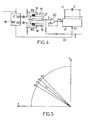
- Un integrated circuit for measuring such a variation in capacity, with sensors providing signals pulses modulated in phase is represented in the figure 4.
- the sensor has several unit cells and a common flyweight in the shape of a comb.
- the detector capacity variation is composed of fixed teeth independent 15, 16 and movable central teeth 17 integral with the flyweight and which move in function of the applied acceleration, that is to say in function of the inclination of the relevant sensor of the housing inclinometer fixed to the clamp body, relative to the axis vertical reference. Both abilities as well formed between the central teeth 17 and the teeth mobile 15 on the one hand, 16 on the other hand, are connected in series to form a capacitive divider with the armature mobile unit carrying the teeth 17.
- Fixed frames bearing the teeth 15, 16 are driven in differential by a signal of for example 1 MHz frequency, supplied by a oscillator 18 in the form of two signals s1 and s2 from same amplitude but 180 ° out of phase. At rest, the values of the two capacities 15-17 and 16-17 are equal, and the tension of the central reinforcement is zero.
- the armatures of the central flyweight move towards one of two sets of fixed frames 15 or 16, which creates a imbalance between the two capacities and, on the armature central, a signal s whose amplitude varies in proportion to the acceleration applied.
- Voltage is "buffered” at 20 and applied to a demodulator synchronous 21 whose clock is controlled (link 22) in phase by oscillator 18.
- the output c1 of this demodulator is positive if the voltage s is synchronous and in phase with the clock, and negative if the signals are 180 ° phase shifted, all other signals being filtered.
- the external capacity C fixes the bandwidth of the receiver 21.
Landscapes
- Engineering & Computer Science (AREA)
- Mechanical Engineering (AREA)
- Resistance Welding (AREA)
- Butt Welding And Welding Of Specific Article (AREA)
Abstract
Description
- la figure 1 représente une pince manuelle de soudage électrique par points suspendue à une élingue et manipulée par un opérateur;
- la figure 2 est une vue en élévation plus détaillée de cette pince, et la figure 3 une vue de dessus, sans les électrodes ;
- la figure 4 représente un circuit utilisable pour la mesure d'une variation de capacité de l'accéléromètre ;
- la figure 5 montre schématiquement le découpage de l'espace entre un axe du corps de la pince et la direction verticale de référence, utilisable par exemple pour la programmation des points de soudage et des zones de soudage acceptables pour ce point.
Claims (13)
- Procédé de sélection automatique d'une séquence de soudage pour pince de soudage manuelle, s'agissant en particulier d'une pince manuelle de soudage électrique à résistance par points pour l'assemblage de tôles, du type comportant un corps (1) de pince relié par un câble souple (4) à une alimentation en courant électrique et portant éventuellement un transformateur-abaisseur propre à alimenter la pince de soudage en courant à haute intensité, ledit corps de pince étant suspendu par l'intermédiaire d'une liaison articulée (9, 13, 14) à une élingue (6) s'étendant au repos selon un axe vertical et pourvue préférentiellement d'un enrouleur-équilibreur (7), laquelle liaison articulée comprend d'une part une couronne circulaire (13) de pivotement à l'intérieur de laquelle ledit corps (1) de pince peut tourner autour d'un axe principal, longitudinal et orientable (X), d'autre part un pivot (14) monté sur ladite couronne circulaire (13) et grâce auquel ladite couronne et donc le corps (1) de la pince peuvent pivoter sur l'extrémité inférieure de ladite élingue (6) autour d'un axe horizontal et latéral (y) perpendiculaire audit axe longitudinal (X), cette pince comportant par ailleurs au moins une poignée de manipulation (10, 11) à l'aide de laquelle un opérateur peut orienter convenablement la pince par rapport aux tôles à souder, suite à quoi il peut déclencher ladite séquence de soudage en actionnant une commande (12) sur la pince, caractérisé en ce que ledit corps (1) de la pince est solidaire d'un boítier d'inclinomètre, lequel est adapté à fournir sous la forme de signaux au moins deux informations :par suite de quoi ces informations sont utilisées pour identifier l'emplacement de soudage et effectuer la sélection automatique de la séquence de soudage appropriée correspondant à cet emplacement, la séquence de soudage identifiée étant codée de façon à pouvoir être transférée puis exécutée par une armoire de commande de soudage.a) une information représentative de la valeur et du sens de l'angle de pivotement dudit corps (1) de pince autour dudit axe principal et longitudinal (X) par rapport à un axe de référence (V) ; etb) une information représentative de la valeur et du sens de l'angle de pivotement dudit corps (1) de pince autour dudit axe latéral (y), par rapport audit axe de référence (V),
- Procédé selon la revendication 1, caractérisé par une phase préalable de programmation ou de reprogrammation des différents points de soudage en mode "apprentissage", effectuée par l'intermédiaire d'une interface séparée de ladite pince, prévue sur un boítier mobile et autonome, et propre à être connectée à ladite armoire de commande au moment de cette programmation ou reprogrammation, ladite phase consistant, pour chaque point de soudage, à positionner la pince de soudage dans la position souhaitée au point de soudage concerné et à enregistrer dans une mémoire les angles caractéristiques du pivotement du corps (1) de la pince autour desdits axes longitudinal (X) et latéral (y) ainsi que les tolérances acceptables pour ces angles, et l'identification du numéro de la séquence de soudage souhaitée au point considéré, une reprogrammation étant précédée par une opération d'effacement, de ladite mémoire, des paramètres précédemment enregistrés.
- Procédé selon la revendication 1 ou 2, caractérisé en ce que l'on programme dans un séquenceur de soudage un ordre déterminé de déroulement des séquences de soudage, et l'on vérifie, grâce audit boítier d'inclinomètre, sa concordance avec la séquence détectée.
- Procédé selon l'une quelconque des revendications précédentes, caractérisé par la mise en oeuvre d'une opération de vérification de la position des électrodes, par rapport aux tôles à souder, à l'emplacement de la soudure, afin de contrôler que l'opérateur oriente convenablement la pince en cet emplacement.
- Procédé selon l'une quelconque des revendications précédentes, caractérisé en ce que ledit boítier d'inclinomètre comprend au moins deux accéléromètres propres à mesurer les déplacements angulaires, par rapport à un axe de référence vertical (V), desdits axes longitudinal (X) et latéral (y) du corps de la pince.
- Procédé selon la revendication 5, caractérisé en ce que ledit boítier d'inclinomètre comprend un troisième accéléromètre propre à mesurer les déplacements angulaires, par rapport audit axe de référence vertical (V), d'un troisième axe (Z) du corps (1) de la pince de soudage, perpendiculaire auxdits axes latéral et longitudinal (X).
- Procédé selon la revendication 5 ou 6, caractérisé en ce que chacun des plans verticaux contenant les axes longitudinal (X) et latéral (y) du corps de la pince est divisé, de part et d'autre du plan horizontal, en un certain nombre de secteurs identifiables, le repérage de l'orientation de la pince s'effectuant alors par l'identification des deux secteurs dans lesquels se trouve l'axe des deux accéléromètres respectifs correspondants.
- Procédé selon l'une quelconque des revendications 5 à 7, caractérisé en ce que ledit corps (1) de la pince porte supplémentairement un détecteur de rotation autour dudit axe de référence vertical (V).
- Pince manuelle de soudage électrique par points pour la mise en oeuvre d'un procédé conforme à l'une quelconque des revendications précédentes, du type comportant un corps (1) de pince relié par un câble souple (4) à une alimentation en courant électrique et portant éventuellement un transformateur-abaisseur propre à alimenter la pince de soudage en courant à haute intensité, ledit corps (1) de pince étant suspendu par l'intermédiaire d'une liaison articulée (9, 13, 14) à une élingue (6) s'étendant au repos suivant la verticale et pourvue préférentiellement d'un enrouleur-équilibreur (7), cette liaison articulée comprenant d'une part une couronne circulaire de pivotement (13) à l'intérieur de laquelle ledit corps (1) de pince peut tourner autour d'un axe principal, longitudinal et orientable (X), d'autre part un pivot (14) monté sur ladite couronne circulaire (13) et grâce auquel ladite couronne et donc le corps (1) de la pince peuvent pivoter sur l'extrémité inférieure de ladite élingue (6) autour d'un axe horizontal et latéral (y) perpendiculaire audit axe longitudinal (X), cette pince comportant également au moins une poignée de manipulation (10, 11) à l'aide de laquelle un opérateur peut orienter convenablement la pince par rapport aux tôles à souder, suite à quoi il peut déclencher ladite séquence de soudage en actionnant une commande par gâchette ou analogue (12) sur la pince, caractérisée en ce que ledit corps (1) de la pince porte un boítier d'inclinomètre, lequel est adapté à fournir sous la forme de signaux au moins deux informations :par suite de quoi ces informations sont utilisées pour identifier l'emplacement de soudage et effectuer la sélection automatique de la séquence de soudage appropriée correspondant à cet emplacement, la séquence de soudage identifiée étant codée de façon à pouvoir être transférée puis exécutée par une armoire de commande de soudage.a) une information représentative de la valeur et du sens de l'angle de pivotement dudit corps (1) de pince autour dudit axe principal et longitudinal (X) par rapport à un axe de référence (V); etb) une information représentative de la valeur et du sens de l'angle de pivotement dudit corps (1) de pince autour dudit axe latéral (y) par rapport audit axe de référence(V),
- Pince selon la revendication 9, caractérisée en ce que ledit boítier d'inclinomètre comprend au moins deux accéléromètres propres à mesurer les déplacements angulaires, par rapport à un axe de référence vertical (V), desdits axes longitudinal (X) et latéral (y) du corps de la pince.
- Pince selon la revendication 9 ou 10, caractérisée en ce que ledit boítier d'inclinomètre comprend un troisième accéléromètre propre à mesurer les déplacements angulaires, par rapport audit axe de référence vertical (V), d'un troisième axe (Z) du corps (1) de la pince de soudage, perpendiculaire auxdits axes latéral (y) et longitudinal (X).
- Pince selon l'une quelconque des revendications 9 à 11, caractérisée en ce que ledit corps (1) de la pince porte supplémentairement un détecteur de rotation autour dudit axe de référence vertical (V).
- Pince selon la revendication 10 ou 11, caractérisée en ce que lesdits accéléromètres sont de type capacitif et fournissent un signal d'inclinaison du type à impulsions modulées en largeur.
Applications Claiming Priority (2)
| Application Number | Priority Date | Filing Date | Title |
|---|---|---|---|
| FR9910813 | 1999-08-26 | ||
| FR9910813A FR2797794B1 (fr) | 1999-08-26 | 1999-08-26 | Procede de selection automatique de sequence de soudage pour pince de soudage manuelle; pince de soudage manuelle pour la mise en oeuvre du procede |
Publications (2)
| Publication Number | Publication Date |
|---|---|
| EP1078707A1 true EP1078707A1 (fr) | 2001-02-28 |
| EP1078707B1 EP1078707B1 (fr) | 2004-02-11 |
Family
ID=9549354
Family Applications (1)
| Application Number | Title | Priority Date | Filing Date |
|---|---|---|---|
| EP00402344A Expired - Lifetime EP1078707B1 (fr) | 1999-08-26 | 2000-08-23 | Procédé de selection automatique de séquence de soudage pour pince de soudage manuelle et pince de soudage manuelle pour la mise en oeuvre du procédé |
Country Status (11)
| Country | Link |
|---|---|
| US (1) | US6337458B1 (fr) |
| EP (1) | EP1078707B1 (fr) |
| JP (1) | JP2001105157A (fr) |
| AR (1) | AR025377A1 (fr) |
| BR (1) | BR0003804A (fr) |
| CA (1) | CA2316685A1 (fr) |
| DE (1) | DE60008175T2 (fr) |
| ES (1) | ES2215009T3 (fr) |
| FR (1) | FR2797794B1 (fr) |
| MX (1) | MXPA00008394A (fr) |
| ZA (1) | ZA200004412B (fr) |
Cited By (6)
| Publication number | Priority date | Publication date | Assignee | Title |
|---|---|---|---|---|
| EP2094426A4 (fr) * | 2006-12-20 | 2015-10-21 | Lincoln Global Inc | Séquenceur de travaux de soudage |
| US9937577B2 (en) | 2006-12-20 | 2018-04-10 | Lincoln Global, Inc. | System for a welding sequencer |
| CN112719551A (zh) * | 2021-04-02 | 2021-04-30 | 新乡职业技术学院 | 一种悬挂焊接机器人智能升降装置 |
| US10994357B2 (en) | 2006-12-20 | 2021-05-04 | Lincoln Global, Inc. | System and method for creating or modifying a welding sequence |
| US10994358B2 (en) | 2006-12-20 | 2021-05-04 | Lincoln Global, Inc. | System and method for creating or modifying a welding sequence based on non-real world weld data |
| US11072034B2 (en) | 2006-12-20 | 2021-07-27 | Lincoln Global, Inc. | System and method of exporting or using welding sequencer data for external systems |
Families Citing this family (52)
| Publication number | Priority date | Publication date | Assignee | Title |
|---|---|---|---|---|
| DE102007062384A1 (de) * | 2007-12-22 | 2009-06-25 | Robert Bosch Gmbh | Einrichtung mit integriertem Lagesensor |
| WO2009146359A1 (fr) | 2008-05-28 | 2009-12-03 | Illinois Tool Works Inc. | Système de formation au soudage |
| JP2010058153A (ja) * | 2008-09-05 | 2010-03-18 | Honda Motor Co Ltd | ポータブルガン |
| US9993891B2 (en) | 2010-07-14 | 2018-06-12 | Illinois Tool Works Inc. | Welding parameter control via welder motion or position monitoring |
| US9101994B2 (en) | 2011-08-10 | 2015-08-11 | Illinois Tool Works Inc. | System and device for welding training |
| US9573215B2 (en) | 2012-02-10 | 2017-02-21 | Illinois Tool Works Inc. | Sound-based weld travel speed sensing system and method |
| US9583014B2 (en) | 2012-11-09 | 2017-02-28 | Illinois Tool Works Inc. | System and device for welding training |
| US9368045B2 (en) | 2012-11-09 | 2016-06-14 | Illinois Tool Works Inc. | System and device for welding training |
| US9666100B2 (en) | 2013-03-15 | 2017-05-30 | Illinois Tool Works Inc. | Calibration devices for a welding training system |
| US9728103B2 (en) | 2013-03-15 | 2017-08-08 | Illinois Tool Works Inc. | Data storage and analysis for a welding training system |
| US9583023B2 (en) | 2013-03-15 | 2017-02-28 | Illinois Tool Works Inc. | Welding torch for a welding training system |
| US9713852B2 (en) | 2013-03-15 | 2017-07-25 | Illinois Tool Works Inc. | Welding training systems and devices |
| US9672757B2 (en) | 2013-03-15 | 2017-06-06 | Illinois Tool Works Inc. | Multi-mode software and method for a welding training system |
| CN103170781B (zh) * | 2013-04-09 | 2015-08-19 | 东风汽车公司 | 焊钳杆式转动吊架 |
| US11090753B2 (en) | 2013-06-21 | 2021-08-17 | Illinois Tool Works Inc. | System and method for determining weld travel speed |
| US10056010B2 (en) | 2013-12-03 | 2018-08-21 | Illinois Tool Works Inc. | Systems and methods for a weld training system |
| US9724788B2 (en) | 2014-01-07 | 2017-08-08 | Illinois Tool Works Inc. | Electrical assemblies for a welding system |
| US10105782B2 (en) | 2014-01-07 | 2018-10-23 | Illinois Tool Works Inc. | Feedback from a welding torch of a welding system |
| US9589481B2 (en) | 2014-01-07 | 2017-03-07 | Illinois Tool Works Inc. | Welding software for detection and control of devices and for analysis of data |
| US9751149B2 (en) | 2014-01-07 | 2017-09-05 | Illinois Tool Works Inc. | Welding stand for a welding system |
| US9757819B2 (en) | 2014-01-07 | 2017-09-12 | Illinois Tool Works Inc. | Calibration tool and method for a welding system |
| US10170019B2 (en) | 2014-01-07 | 2019-01-01 | Illinois Tool Works Inc. | Feedback from a welding torch of a welding system |
| US10665128B2 (en) | 2014-06-27 | 2020-05-26 | Illinois Tool Works Inc. | System and method of monitoring welding information |
| US9862049B2 (en) | 2014-06-27 | 2018-01-09 | Illinois Tool Works Inc. | System and method of welding system operator identification |
| US9937578B2 (en) | 2014-06-27 | 2018-04-10 | Illinois Tool Works Inc. | System and method for remote welding training |
| US10307853B2 (en) | 2014-06-27 | 2019-06-04 | Illinois Tool Works Inc. | System and method for managing welding data |
| US9724787B2 (en) | 2014-08-07 | 2017-08-08 | Illinois Tool Works Inc. | System and method of monitoring a welding environment |
| US11014183B2 (en) | 2014-08-07 | 2021-05-25 | Illinois Tool Works Inc. | System and method of marking a welding workpiece |
| US9875665B2 (en) | 2014-08-18 | 2018-01-23 | Illinois Tool Works Inc. | Weld training system and method |
| US10987762B2 (en) | 2014-09-30 | 2021-04-27 | Illinois Tool Works Inc. | Armband based systems and methods for controlling welding equipment using gestures and like motions |
| US10201868B2 (en) | 2014-09-30 | 2019-02-12 | Illinois Tool Works Inc. | Systems and methods for gesture control of a welding system |
| US11247289B2 (en) | 2014-10-16 | 2022-02-15 | Illinois Tool Works Inc. | Remote power supply parameter adjustment |
| US10239147B2 (en) | 2014-10-16 | 2019-03-26 | Illinois Tool Works Inc. | Sensor-based power controls for a welding system |
| US10402959B2 (en) | 2014-11-05 | 2019-09-03 | Illinois Tool Works Inc. | System and method of active torch marker control |
| US10373304B2 (en) | 2014-11-05 | 2019-08-06 | Illinois Tool Works Inc. | System and method of arranging welding device markers |
| US10490098B2 (en) | 2014-11-05 | 2019-11-26 | Illinois Tool Works Inc. | System and method of recording multi-run data |
| US10210773B2 (en) | 2014-11-05 | 2019-02-19 | Illinois Tool Works Inc. | System and method for welding torch display |
| US10204406B2 (en) | 2014-11-05 | 2019-02-12 | Illinois Tool Works Inc. | System and method of controlling welding system camera exposure and marker illumination |
| US10417934B2 (en) | 2014-11-05 | 2019-09-17 | Illinois Tool Works Inc. | System and method of reviewing weld data |
| US10427239B2 (en) | 2015-04-02 | 2019-10-01 | Illinois Tool Works Inc. | Systems and methods for tracking weld training arc parameters |
| US10593230B2 (en) | 2015-08-12 | 2020-03-17 | Illinois Tool Works Inc. | Stick welding electrode holder systems and methods |
| US10438505B2 (en) | 2015-08-12 | 2019-10-08 | Illinois Tool Works | Welding training system interface |
| US10657839B2 (en) | 2015-08-12 | 2020-05-19 | Illinois Tool Works Inc. | Stick welding electrode holders with real-time feedback features |
| US10373517B2 (en) | 2015-08-12 | 2019-08-06 | Illinois Tool Works Inc. | Simulation stick welding electrode holder systems and methods |
| KR20180064866A (ko) * | 2016-12-06 | 2018-06-15 | 현대자동차주식회사 | 용접건 및 이를 구비한 편방향 용접 시스템 |
| US11224932B2 (en) * | 2018-04-12 | 2022-01-18 | Medtronic, Inc. | Resistance spot weld head with integrated accelerometer |
| WO2019203279A1 (fr) * | 2018-04-20 | 2019-10-24 | パナソニックIpマネジメント株式会社 | Machine à souder |
| US11776423B2 (en) | 2019-07-22 | 2023-10-03 | Illinois Tool Works Inc. | Connection boxes for gas tungsten arc welding training systems |
| US11288978B2 (en) | 2019-07-22 | 2022-03-29 | Illinois Tool Works Inc. | Gas tungsten arc welding training systems |
| US12279993B2 (en) | 2020-07-31 | 2025-04-22 | Illinois Tool Works Inc. | Smart welding helmet modules with adaptable helmet devices |
| US12433792B2 (en) | 2020-12-14 | 2025-10-07 | Illinois Tool Works Inc. | Smart welding helmets with arc time tracking verification and lens maintenance detection |
| US12530984B2 (en) | 2023-12-13 | 2026-01-20 | Illinois Tool Works Inc. | Welding systems with automatic welding instruction generation |
Citations (3)
| Publication number | Priority date | Publication date | Assignee | Title |
|---|---|---|---|---|
| JPH03243285A (ja) * | 1990-02-21 | 1991-10-30 | Takaoka Electric Mfg Co Ltd | スポット溶接における溶接強度の管理方法 |
| JPH08206846A (ja) * | 1995-02-06 | 1996-08-13 | Kawasaki Heavy Ind Ltd | スポット溶接方法および装置 |
| JPH10216955A (ja) * | 1996-12-06 | 1998-08-18 | Mazda Motor Corp | スポット溶接における電極角度設定方法及びその装置 |
Family Cites Families (7)
| Publication number | Priority date | Publication date | Assignee | Title |
|---|---|---|---|---|
| US3529118A (en) * | 1968-03-22 | 1970-09-15 | Hughes Aircraft Co | Portable spot welding handpiece |
| US4590577A (en) * | 1982-12-01 | 1986-05-20 | Yaskawa Electric Mfg. Co., Ltd. | Welding robot controlling method |
| US4937759A (en) * | 1986-02-18 | 1990-06-26 | Robotics Research Corporation | Industrial robot with controller |
| SU1785153A1 (ru) * | 1989-11-29 | 1996-08-27 | Всесоюзный научно-исследовательский, проектно-конструкторский и технологический институт электросварочного оборудования | Подвесная сварочная машина |
| CA2017674C (fr) * | 1990-05-30 | 1995-06-13 | Henning Hansen | Bras de support articule pour equipement de soudure |
| US5493093A (en) * | 1992-07-09 | 1996-02-20 | Cecil; Dimitrios G. | Computer-integrated multi-gun welding system |
| GB2315135B (en) * | 1996-07-10 | 2000-12-06 | Honda Motor Co Ltd | Control apparatus for welding robot |
-
1999
- 1999-08-26 FR FR9910813A patent/FR2797794B1/fr not_active Expired - Fee Related
-
2000
- 2000-08-23 DE DE60008175T patent/DE60008175T2/de not_active Expired - Fee Related
- 2000-08-23 EP EP00402344A patent/EP1078707B1/fr not_active Expired - Lifetime
- 2000-08-23 CA CA002316685A patent/CA2316685A1/fr not_active Abandoned
- 2000-08-23 ES ES00402344T patent/ES2215009T3/es not_active Expired - Lifetime
- 2000-08-23 US US09/643,923 patent/US6337458B1/en not_active Expired - Fee Related
- 2000-08-24 AR ARP000104397A patent/AR025377A1/es unknown
- 2000-08-25 MX MXPA00008394A patent/MXPA00008394A/es unknown
- 2000-08-25 ZA ZA200004412A patent/ZA200004412B/xx unknown
- 2000-08-25 BR BR0003804-0A patent/BR0003804A/pt not_active Application Discontinuation
- 2000-08-28 JP JP2000257778A patent/JP2001105157A/ja active Pending
Patent Citations (3)
| Publication number | Priority date | Publication date | Assignee | Title |
|---|---|---|---|---|
| JPH03243285A (ja) * | 1990-02-21 | 1991-10-30 | Takaoka Electric Mfg Co Ltd | スポット溶接における溶接強度の管理方法 |
| JPH08206846A (ja) * | 1995-02-06 | 1996-08-13 | Kawasaki Heavy Ind Ltd | スポット溶接方法および装置 |
| JPH10216955A (ja) * | 1996-12-06 | 1998-08-18 | Mazda Motor Corp | スポット溶接における電極角度設定方法及びその装置 |
Non-Patent Citations (3)
| Title |
|---|
| PATENT ABSTRACTS OF JAPAN vol. 16, no. 34 (M - 1204) 28 January 1992 (1992-01-28) * |
| PATENT ABSTRACTS OF JAPAN vol. 1996, no. 12 26 December 1996 (1996-12-26) * |
| PATENT ABSTRACTS OF JAPAN vol. 1998, no. 13 30 November 1998 (1998-11-30) * |
Cited By (9)
| Publication number | Priority date | Publication date | Assignee | Title |
|---|---|---|---|---|
| EP2094426A4 (fr) * | 2006-12-20 | 2015-10-21 | Lincoln Global Inc | Séquenceur de travaux de soudage |
| US9937577B2 (en) | 2006-12-20 | 2018-04-10 | Lincoln Global, Inc. | System for a welding sequencer |
| US10496080B2 (en) | 2006-12-20 | 2019-12-03 | Lincoln Global, Inc. | Welding job sequencer |
| US10940555B2 (en) | 2006-12-20 | 2021-03-09 | Lincoln Global, Inc. | System for a welding sequencer |
| US10994357B2 (en) | 2006-12-20 | 2021-05-04 | Lincoln Global, Inc. | System and method for creating or modifying a welding sequence |
| US10994358B2 (en) | 2006-12-20 | 2021-05-04 | Lincoln Global, Inc. | System and method for creating or modifying a welding sequence based on non-real world weld data |
| US11072034B2 (en) | 2006-12-20 | 2021-07-27 | Lincoln Global, Inc. | System and method of exporting or using welding sequencer data for external systems |
| US11980976B2 (en) | 2006-12-20 | 2024-05-14 | Lincoln Global, Inc. | Method for a welding sequencer |
| CN112719551A (zh) * | 2021-04-02 | 2021-04-30 | 新乡职业技术学院 | 一种悬挂焊接机器人智能升降装置 |
Also Published As
| Publication number | Publication date |
|---|---|
| FR2797794B1 (fr) | 2001-11-09 |
| ES2215009T3 (es) | 2004-10-01 |
| DE60008175D1 (de) | 2004-03-18 |
| JP2001105157A (ja) | 2001-04-17 |
| DE60008175T2 (de) | 2004-09-16 |
| CA2316685A1 (fr) | 2001-02-26 |
| MXPA00008394A (es) | 2005-07-15 |
| ZA200004412B (en) | 2001-08-27 |
| AR025377A1 (es) | 2002-11-20 |
| FR2797794A1 (fr) | 2001-03-02 |
| EP1078707B1 (fr) | 2004-02-11 |
| US6337458B1 (en) | 2002-01-08 |
| BR0003804A (pt) | 2001-11-27 |
Similar Documents
| Publication | Publication Date | Title |
|---|---|---|
| EP1078707B1 (fr) | Procédé de selection automatique de séquence de soudage pour pince de soudage manuelle et pince de soudage manuelle pour la mise en oeuvre du procédé | |
| CA2002513C (fr) | Methode et dispositif de detection automatique du profil d'une surface et en vue d'effectuer un travail | |
| EP1600730B1 (fr) | Appareil de lecture de contour comportant un palpeur mobile en rotation | |
| CA1080190A (fr) | Methode et dispositif de rangement automatique d'un element allonge flexible dans un panier tournant d'axe vertical | |
| EP0853527B1 (fr) | Dispositif de mesure ou de controle de l'usinage d'une piece cylindrique a mouvement orbital | |
| EP0034967B1 (fr) | Procédé automatique et auto-adaptatif de soudage par fusion et dispositif pour la mise en oeuvre de ce procédé | |
| FR2575516A1 (fr) | Appareil pour mesurer l'inclinaison et l'azimut d'un sondage et procede pour empecher l'endommagement des organes d'un inclinometre | |
| JP2652521B2 (ja) | つりあい試験機および車輪の不つりあい修正方法 | |
| FR2465562A1 (fr) | Appareil de blocage pour fixer un bloc metallique sur la face finie d'une ebauche semi-finie de lentille ophtalmique | |
| FR2481443A1 (fr) | Appareil pour controler l'exactitude de dimensions d'objets volumineux | |
| FR2739181A1 (fr) | Dispositif et procede de controle de la geometrie d'un trou creuse dans une piece | |
| EP3189266B1 (fr) | Ensemble d'intervention sur la surface externe d'un tube, et procédé correspondant | |
| EP0329531A1 (fr) | Procédé et dispositif pour l'estimation des paramètres du modèle géométrique d'un manipulateur | |
| EP3414040B1 (fr) | Dispositif pour la soudure automatique d'un joint, notamment un joint de bordée | |
| EP1173723B1 (fr) | Procede de contrôle de la geometrie de vehicule automobile | |
| FR2538744A1 (fr) | Porte-organe adaptatif utilisable en telemanipulation ou robotique | |
| EP1697693B1 (fr) | Dispositif permettant de controler un banc destine a mesurer, regler et/ou controler un train roulant de vehiclule automobile | |
| EP0991496B1 (fr) | Procede et appareil de palpage de montures de lunettes, et machine de meulage correspondante | |
| EP3031983A1 (fr) | Procédé amélioré de guidage d'un dispositif d'insertion d'éléments dans le sol pour la réalisation d'un ouvrage ; dispositif d'insertion et véhicule associés | |
| EP2865633A1 (fr) | Equilibreur à descente préliminaire automatique et descente finale manuelle | |
| EP0056554A2 (fr) | Dispositif de contrôle en service de l'intégrité des soudures des structures off-shore | |
| FR2526696A1 (fr) | Procede et dispositif pour la commande et le controle de la position entre deux bords metalliques d'un organe de soudage a l'arc | |
| EP0343140A2 (fr) | Procédé et dispositif pour surveiller la progression dans le sol d'une tête de forage | |
| CA2410282A1 (fr) | Procede de deplacement automatique sur un terrain, d'un outil monte a l'extremite d'un bras articule | |
| EP1097757A1 (fr) | Procédé et dispositif de contrôle de la qualité des formages réalisés par une machine a former des extrémités de tubes |
Legal Events
| Date | Code | Title | Description |
|---|---|---|---|
| PUAI | Public reference made under article 153(3) epc to a published international application that has entered the european phase |
Free format text: ORIGINAL CODE: 0009012 |
|
| AK | Designated contracting states |
Kind code of ref document: A1 Designated state(s): BE DE ES GB IT SE |
|
| AX | Request for extension of the european patent |
Free format text: AL;LT;LV;MK;RO;SI |
|
| 17P | Request for examination filed |
Effective date: 20010709 |
|
| AKX | Designation fees paid |
Free format text: BE DE ES GB IT SE |
|
| GRAH | Despatch of communication of intention to grant a patent |
Free format text: ORIGINAL CODE: EPIDOS IGRA |
|
| RTI1 | Title (correction) |
Free format text: AUTOMATIC SELECTION METHOD OF WELDING SEQUENCES FOR A MANUAL WELDING GUN AND MANUAL WELDING GUN USED TO CARRY OUT THE MET |
|
| GRAS | Grant fee paid |
Free format text: ORIGINAL CODE: EPIDOSNIGR3 |
|
| GRAA | (expected) grant |
Free format text: ORIGINAL CODE: 0009210 |
|
| AK | Designated contracting states |
Kind code of ref document: B1 Designated state(s): BE DE ES GB IT SE |
|
| REG | Reference to a national code |
Ref country code: GB Ref legal event code: FG4D Free format text: NOT ENGLISH |
|
| REF | Corresponds to: |
Ref document number: 60008175 Country of ref document: DE Date of ref document: 20040318 Kind code of ref document: P |
|
| PG25 | Lapsed in a contracting state [announced via postgrant information from national office to epo] |
Ref country code: SE Free format text: LAPSE BECAUSE OF FAILURE TO SUBMIT A TRANSLATION OF THE DESCRIPTION OR TO PAY THE FEE WITHIN THE PRESCRIBED TIME-LIMIT Effective date: 20040511 |
|
| GBT | Gb: translation of ep patent filed (gb section 77(6)(a)/1977) |
Effective date: 20040517 |
|
| PG25 | Lapsed in a contracting state [announced via postgrant information from national office to epo] |
Ref country code: GB Free format text: LAPSE BECAUSE OF NON-PAYMENT OF DUE FEES Effective date: 20040823 |
|
| PG25 | Lapsed in a contracting state [announced via postgrant information from national office to epo] |
Ref country code: ES Free format text: LAPSE BECAUSE OF NON-PAYMENT OF DUE FEES Effective date: 20040824 |
|
| PG25 | Lapsed in a contracting state [announced via postgrant information from national office to epo] |
Ref country code: BE Free format text: LAPSE BECAUSE OF NON-PAYMENT OF DUE FEES Effective date: 20040831 |
|
| REG | Reference to a national code |
Ref country code: ES Ref legal event code: FG2A Ref document number: 2215009 Country of ref document: ES Kind code of ref document: T3 |
|
| PLBE | No opposition filed within time limit |
Free format text: ORIGINAL CODE: 0009261 |
|
| STAA | Information on the status of an ep patent application or granted ep patent |
Free format text: STATUS: NO OPPOSITION FILED WITHIN TIME LIMIT |
|
| 26N | No opposition filed |
Effective date: 20041112 |
|
| BERE | Be: lapsed |
Owner name: *ARO Effective date: 20040831 |
|
| PG25 | Lapsed in a contracting state [announced via postgrant information from national office to epo] |
Ref country code: DE Free format text: LAPSE BECAUSE OF NON-PAYMENT OF DUE FEES Effective date: 20050301 |
|
| GBPC | Gb: european patent ceased through non-payment of renewal fee |
Effective date: 20040823 |
|
| PG25 | Lapsed in a contracting state [announced via postgrant information from national office to epo] |
Ref country code: IT Free format text: LAPSE BECAUSE OF NON-PAYMENT OF DUE FEES Effective date: 20050823 |
|
| REG | Reference to a national code |
Ref country code: ES Ref legal event code: FD2A Effective date: 20040824 |
|
| BERE | Be: lapsed |
Owner name: *ARO Effective date: 20040831 |