EP1078564B1 - Epandeur d'engrais centrifuge - Google Patents
Epandeur d'engrais centrifuge Download PDFInfo
- Publication number
- EP1078564B1 EP1078564B1 EP00117052A EP00117052A EP1078564B1 EP 1078564 B1 EP1078564 B1 EP 1078564B1 EP 00117052 A EP00117052 A EP 00117052A EP 00117052 A EP00117052 A EP 00117052A EP 1078564 B1 EP1078564 B1 EP 1078564B1
- Authority
- EP
- European Patent Office
- Prior art keywords
- outlet
- metering
- spreader according
- members
- disposed
- Prior art date
- Legal status (The legal status is an assumption and is not a legal conclusion. Google has not performed a legal analysis and makes no representation as to the accuracy of the status listed.)
- Expired - Lifetime
Links
Images


Classifications
-
- A—HUMAN NECESSITIES
- A01—AGRICULTURE; FORESTRY; ANIMAL HUSBANDRY; HUNTING; TRAPPING; FISHING
- A01C—PLANTING; SOWING; FERTILISING
- A01C17/00—Fertilisers or seeders with centrifugal wheels
- A01C17/006—Regulating or dosing devices
Definitions
- the invention relates to a centrifugal fertilizer spreader according to Preamble of claim 1.
- Such a centrifugal fertilizer spreader is, for example, in DE-OS 43 02 802 described.
- This fertilizer spreader is at the lower portion of the reservoir via a flange member arranged a discharge element, which is a dosing assigned.
- This dosing is as in the bottom plate arranged outlet opening with associated slide, by means the outlet opening in its opening size adjustable is, trained.
- the metering device is for a particular Quantity range designed. In particular, if at large working widths very large quantities of material are applied should, it turned out that the desired big Quantities are not in every case ausbringbar.
- Auslaufetti provided with different sized outlet openings are, wherein the size of the outlet elements at least in the area the outlet opening to the size of the outlet opening adapted adapted. This is achieved in particular that very small residues in the emptying of Reservoir remain in the reservoir.
- the outlet elements let out non-rusting material, in particular of plastic material or metal casting.
- the outlet element on the Flange element displaceable relative to the centrifugal disc is arranged.
- a task point shift of the material on the slinger in be achieved in a simple manner, so the centrifugal fertilizer spreader for example, in a simple way of normal sprinkling to border confusion or set upside down.
- a Scale is arranged, at which the opening position of the Slider is adjustable.
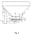
- the centrifugal fertilizer spreader has the reservoir 1.
- the reservoir 1 is connected to the supporting frame 2 with the Three-point coupling elements 3 arranged.
- the storage tank 1 is through a roof-shaped center part 4 in the two Outlet funnels 5 and 6 divided.
- the outlet funnel 5 and 6 each pass into an outlet 7, which in each case a Dosing 8 is assigned.
- Below the metering 8 are located with throwing blades 9 occupied centrifugal discs 10, which in an opposite sense of rotation Rotationally driven by a power source.
- the stirring shafts 11 are respectively in the outlet elements 7 and 8 stored.
- the metering 9 have a bottom plate 12 with it arranged, but not shown outlet openings on, via a slider 13 in its opening width adjustable is, wherein the open position of the slider 13th via the cooperating with the stop element 14 scale 15th is adjustable.
- the outlet elements 7 are on the flange 16 at the lower ends of the outlet funnel 5, 6 are arranged.
- the outlet elements 7 with the associated metering 8 are for Small to medium application rates provided.
- the size of the Outlet elements 7 is in the region of the outlet opening to the Size of the outlet opening adapted so that as possible small residual quantities result.
- the outlet elements 7 are made Stainless material, such as plastic material or metal casting produced.
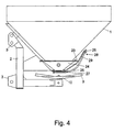
- outlet elements 17 are arranged. These outlet elements 17 have metering 18 with larger outlet openings than in the outlet elements 7 in Figs.1 and 2 located outlet openings. Thus, the dosing 18 for the large application rates larger than the metering 9 designed.
- the metering 18 of the outlet elements 17th have the arranged in the bottom plate 19, but not illustrated outlet opening, via the slider 20 in its opening width is adjustable.
- the opening position of the Slider 20 is determined by the stop 21, based on the scale 15 is adjustable.
- the outlet elements 17 are made stainless material, in particular plastic material or Cast metal produced. In the side wall of the outlet elements the stirring element 22 is mounted.
- outlet elements 7 and 8 on the one hand and 17, on the other hand, interchangeable and optional on the flange member 16 according to the condition of use to arrange or the fertilizer spreader is according to the required To equip conditions of use.
- the intended application rate range Outlet elements 7, 8, 17 with associated metering 9, 18th provided in an exchangeable manner.
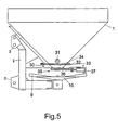
- the flange 23 for the arrangement of relative to the reservoir 1 and the centrifugal disc 11th slidable outlet element 24 is provided.
- the flange 23 itself with slots, due of which the outlet element 24 is displaceable, provided is, or on the flange 23 is an intermediate plate provided in which the sliding guides for displacement the outlet element 24 with respect to the centrifugal disc 11th are arranged.
- the Scale 26 and the Mengeneinstellvoriques 28 are at a on the outlet element 24 upwardly projecting retaining element 29th arranged.
- a not shown adjusting element which is motorized or can be driven between the reservoir 1 and the outlet element 24 is arranged.
- the centrifugal fertilizer spreader according to FIGS. 5 and 6 differs from the centrifugal fertilizer spreader according to FIGS. 1 to 4 by another design of the lower outlet funnel area 30.
- the stirring shaft 31 stored above the flange 32 in the reservoir 1.
- On the flange member 33 is an exchange outlet element 34 with a metering member 35, the slide 36 via a trained as an electric motor electrical actuator 37 is actuated.
- the exchange outlet elements are with the respective metering device as a whole releasably connected to the connecting element formed flange 33 and arranged against one of the exchange outlet elements with the respective exchanged desired metering or interchangeable Way attached.
Landscapes
- Life Sciences & Earth Sciences (AREA)
- Soil Sciences (AREA)
- Environmental Sciences (AREA)
- Fertilizing (AREA)
Claims (14)
- Epandeur centrifuge d'engrais comportant au moins un réservoir ayant au moins partiellement une forme de trémie et dont la zone inférieure comporte au moins un élément de sortie avec un organe de dosage relié par au moins un élément de raccordement,
caractérisé en ce que
plusieurs éléments de sortie remplaçables (7, 17, 24, 34, 38) avec des organes de dosage différents (18, 25, 35, 35') sont prévus pour être montés sur l'élément de raccordement. - Epandeur centrifuge d'engrais selon la revendication 1,
caractérisé en ce que
les éléments de sortie remplaçables (7, 17, 24, 34, 38) sont réalisés par :une installation de dosage (35') munie d'une installation d'actionnement hydraulique (39), ouune installation de dosage (35) avec une installation d'actionnement électrique (37), ouune installation de dosage avec une installation de commande électronique équipée d'une commande et/ou régulation de distribution spécifique à l'emplacement, etles éléments de sortie remplaçables (7, 17, 24, 34, 38) avec l'installation de dosage respective (18, 25, 35, 35') sont montés comme éléments globalement amovibles sur l'élément de branchement (16, 23, 33) et peuvent être remplacés par l'un des éléments de sortie remplaçables équipé de son installation de dosage. - Epandeur centrifuge d'engrais selon l'une quelconque des revendications précédentes,
caractérisé en ce que
l'élément de raccordement (33) se trouve en dessous du palier de l'agitateur (31) dans le réservoir d'alimentation (1). - Epandeur centrifuge d'engrais selon l'une quelconque des revendications précédentes,
caractérisé par
différents éléments de sortie (7, 17, 24, 34, 38) réalisés comme réservoirs de sortie avec des organes de dosage correspondants (18, 25, 35, 35') pour être installés sur l'élément en forme de bride (16, 23, 33). - Epandeur centrifuge d'engrais selon la revendication 4,
caractérisé en ce qu'
en fonction de la plage de quantités à distribuer, on prévoit des éléments de sortie (7, 17, 24) correspondants avec leurs organes de dosage (8, 18, 25) installés de manière remplaçable. - Epandeur centrifuge d'engrais selon la revendication 4, selon lequel l'organe de dosage est un orifice de sortie prévu dans un élément de fond et dont le degré d'ouverture se règle à l'aide d'un élément coulissant coopérant avec l'orifice de sortie,
caractérisé en ce que
des éléments de sortie (7, 17, 24) avec des orifices de sortie de tailles différentes sont prévus, la taille des éléments de sortie (7, 17, 24) étant adaptée au moins au niveau de l'orifice de sortie à la taille de cet orifice de sortie. - Epandeur centrifuge d'engrais selon l'une quelconque des revendications précédentes,
caractérisé en ce que
les éléments de sortie (7, 17, 24) sont réalisés en une matière non oxydable notamment en matière plastique ou en fonte de métal. - Epandeur centrifuge d'engrais selon l'une quelconque des revendications précédentes,
caractérisé en ce qu'
un agitateur (11, 22) est associé à l'organe de dosage (8, 18, 25), cet agitateur étant monté dans la paroi latérale de l'élément de sortie (7, 17, 24) et il est remplacé avec l'élément de sortie. - Epandeur centrifuge d'engrais selon l'une quelconque des revendications précédentes,
caractérisé en ce que
l'élément de sortie (24) est installé de manière coulissante par rapport au disque d'épandage (10) sur l'élément de bride (23). - Epandeur centrifuge d'engrais selon l'une quelconque des revendications précédentes,
caractérisé en ce que
l'élément de sortie (24) comporte une échelle ou graduation (26) sur laquelle se règle la position d'ouverture du tiroir (27). - Epandeur centrifuge d'engrais selon l'une quelconque des revendications précédentes,
caractérisé en ce que
le dispositif de réglage de débit (28) du tiroir (27) est prévu sur l'élément de sortie (24). - Epandeur centrifuge d'engrais selon l'une quelconque des revendications précédentes,
caractérisé en ce que
l'élément de sortie (24) comporte un élément de fixation (29) en saillie vers le haut et muni de l'échelle (26) et de l'installation de réglage de débit (28). - Epandeur centrifuge d'engrais selon l'une quelconque des revendications précédentes,
caractérisé en ce que
la plaque à bride (23) du réservoir d'alimentation (1) et/ou de l'élément de sortie (24) comporte des guides de coulissement. - Epandeur centrifuge d'engrais selon l'une quelconque des revendications précédentes,
caractérisé par
des installations de réglage entre le réservoir (1) et l'élément de sortie (24).
Applications Claiming Priority (2)
| Application Number | Priority Date | Filing Date | Title |
|---|---|---|---|
| DE19939169A DE19939169A1 (de) | 1999-08-20 | 1999-08-20 | Schleuderdüngerstreuer |
| DE19939169 | 1999-08-20 |
Publications (2)
| Publication Number | Publication Date |
|---|---|
| EP1078564A1 EP1078564A1 (fr) | 2001-02-28 |
| EP1078564B1 true EP1078564B1 (fr) | 2004-01-28 |
Family
ID=7918800
Family Applications (1)
| Application Number | Title | Priority Date | Filing Date |
|---|---|---|---|
| EP00117052A Expired - Lifetime EP1078564B1 (fr) | 1999-08-20 | 2000-08-09 | Epandeur d'engrais centrifuge |
Country Status (3)
| Country | Link |
|---|---|
| EP (1) | EP1078564B1 (fr) |
| DE (2) | DE19939169A1 (fr) |
| DK (1) | DK1078564T3 (fr) |
Families Citing this family (3)
| Publication number | Priority date | Publication date | Assignee | Title |
|---|---|---|---|---|
| DE102006019477A1 (de) * | 2006-04-26 | 2007-10-31 | Amazonen-Werke H. Dreyer Gmbh & Co. Kg | Vorrichtung zum Streuen körniger Stoffe |
| DE102012024363A1 (de) * | 2012-12-13 | 2014-06-18 | Rauch Landmaschinenfabrik Gmbh | Verteilmaschine |
| DE102016002827A1 (de) * | 2016-03-09 | 2017-09-14 | Rauch Landmaschinenfabrik Gmbh | Verteilmaschine |
Family Cites Families (4)
| Publication number | Priority date | Publication date | Assignee | Title |
|---|---|---|---|---|
| US3738546A (en) * | 1971-05-10 | 1973-06-12 | Cyclone Seeder Co | Metering device for securement to the hopper or container of a distributor of seeds and other fluent material |
| EP0192089B1 (fr) * | 1985-02-06 | 1991-08-28 | Amazonen-Werke H. Dreyer GmbH & Co. KG | Distributeur à disques, spécialement pour engrais en granulés |
| NL8701870A (nl) * | 1987-08-10 | 1989-03-01 | Lely Nv C Van Der | Machine voor het verspreiden van materiaal. |
| DE4302802A1 (de) | 1993-02-02 | 1994-08-04 | Amazonen Werke Dreyer H | Schleuderdüngerstreuer |
-
1999
- 1999-08-20 DE DE19939169A patent/DE19939169A1/de not_active Withdrawn
-
2000
- 2000-08-09 EP EP00117052A patent/EP1078564B1/fr not_active Expired - Lifetime
- 2000-08-09 DE DE50005123T patent/DE50005123D1/de not_active Expired - Lifetime
- 2000-08-09 DK DK00117052T patent/DK1078564T3/da active
Also Published As
| Publication number | Publication date |
|---|---|
| DE19939169A1 (de) | 2001-02-22 |
| DE50005123D1 (de) | 2004-03-04 |
| EP1078564A1 (fr) | 2001-02-28 |
| DK1078564T3 (da) | 2004-03-08 |
Similar Documents
| Publication | Publication Date | Title |
|---|---|---|
| EP0540889B2 (fr) | Epandeur d'engrais centrifuge | |
| EP0820219B1 (fr) | Epandeur d'engrais centrifuge | |
| DE3641080C2 (de) | Schleuderdüngerstreuer | |
| EP1078564B1 (fr) | Epandeur d'engrais centrifuge | |
| DE4134315A1 (de) | Schleuderduengerstreuer | |
| EP0410112A1 (fr) | Epandeur centrifuge pour matériau coulant, en particulier engrais | |
| EP0951814B1 (fr) | Epandeur centrifuge | |
| DE3616538C2 (fr) | ||
| EP0386540B1 (fr) | Système de fabrication d'une série d'épandeurs de capacité croissante | |
| DE4302802A1 (de) | Schleuderdüngerstreuer | |
| EP0356770B1 (fr) | Distributeurs centrifuges d'engrais | |
| EP0613613A1 (fr) | Epandeur centrifuge | |
| DE4134317C2 (de) | Schleuderdüngerstreuer | |
| DE19829782A1 (de) | Verfahren zum Einstellen eines Zentrifugaldüngerstreuers | |
| DE1924631C3 (de) | Streugerät | |
| DE10033674A1 (de) | Schleuderdüngerstreuer | |
| DE19745441A1 (de) | Schleuderstreuer | |
| DD297905A5 (de) | Schleuderduengerstreuer | |
| DD295966A5 (de) | Zentrifugalduengerstreuer | |
| DE19606586A1 (de) | Schleuderdüngerstreuer | |
| DE19802658A1 (de) | Verteilmaschine | |
| DE19748838A1 (de) | Schleuderstreuer | |
| DE19742440A1 (de) | Schleuderstreuer | |
| DE19714935A1 (de) | Schleuderdüngerstreuer | |
| DE3903967A1 (de) | Landwirtschaftliche verteilmaschine |
Legal Events
| Date | Code | Title | Description |
|---|---|---|---|
| PUAI | Public reference made under article 153(3) epc to a published international application that has entered the european phase |
Free format text: ORIGINAL CODE: 0009012 |
|
| AK | Designated contracting states |
Kind code of ref document: A1 Designated state(s): DE DK FR NL |
|
| AX | Request for extension of the european patent |
Free format text: AL;LT;LV;MK;RO;SI |
|
| 17P | Request for examination filed |
Effective date: 20010510 |
|
| AKX | Designation fees paid |
Free format text: DE DK FR NL |
|
| 17Q | First examination report despatched |
Effective date: 20030221 |
|
| GRAP | Despatch of communication of intention to grant a patent |
Free format text: ORIGINAL CODE: EPIDOSNIGR1 |
|
| GRAS | Grant fee paid |
Free format text: ORIGINAL CODE: EPIDOSNIGR3 |
|
| GRAA | (expected) grant |
Free format text: ORIGINAL CODE: 0009210 |
|
| AK | Designated contracting states |
Kind code of ref document: B1 Designated state(s): DE DK FR NL |
|
| REF | Corresponds to: |
Ref document number: 50005123 Country of ref document: DE Date of ref document: 20040304 Kind code of ref document: P |
|
| REG | Reference to a national code |
Ref country code: DK Ref legal event code: T3 |
|
| ET | Fr: translation filed | ||
| PLBE | No opposition filed within time limit |
Free format text: ORIGINAL CODE: 0009261 |
|
| STAA | Information on the status of an ep patent application or granted ep patent |
Free format text: STATUS: NO OPPOSITION FILED WITHIN TIME LIMIT |
|
| 26N | No opposition filed |
Effective date: 20041029 |
|
| REG | Reference to a national code |
Ref country code: FR Ref legal event code: PLFP Year of fee payment: 17 |
|
| REG | Reference to a national code |
Ref country code: FR Ref legal event code: PLFP Year of fee payment: 18 |
|
| REG | Reference to a national code |
Ref country code: FR Ref legal event code: PLFP Year of fee payment: 19 |
|
| PGFP | Annual fee paid to national office [announced via postgrant information from national office to epo] |
Ref country code: NL Payment date: 20190814 Year of fee payment: 20 |
|
| PGFP | Annual fee paid to national office [announced via postgrant information from national office to epo] |
Ref country code: FR Payment date: 20190711 Year of fee payment: 20 Ref country code: DE Payment date: 20190730 Year of fee payment: 20 Ref country code: DK Payment date: 20190813 Year of fee payment: 20 |
|
| REG | Reference to a national code |
Ref country code: DE Ref legal event code: R071 Ref document number: 50005123 Country of ref document: DE |
|
| REG | Reference to a national code |
Ref country code: DK Ref legal event code: EUP Expiry date: 20200809 |
|
| REG | Reference to a national code |
Ref country code: NL Ref legal event code: MK Effective date: 20200808 |