EP1078564B1 - Fertilizer broadcaster - Google Patents
Fertilizer broadcaster Download PDFInfo
- Publication number
- EP1078564B1 EP1078564B1 EP00117052A EP00117052A EP1078564B1 EP 1078564 B1 EP1078564 B1 EP 1078564B1 EP 00117052 A EP00117052 A EP 00117052A EP 00117052 A EP00117052 A EP 00117052A EP 1078564 B1 EP1078564 B1 EP 1078564B1
- Authority
- EP
- European Patent Office
- Prior art keywords
- outlet
- metering
- spreader according
- members
- disposed
- Prior art date
- Legal status (The legal status is an assumption and is not a legal conclusion. Google has not performed a legal analysis and makes no representation as to the accuracy of the status listed.)
- Expired - Lifetime
Links
Images


Classifications
-
- A—HUMAN NECESSITIES
- A01—AGRICULTURE; FORESTRY; ANIMAL HUSBANDRY; HUNTING; TRAPPING; FISHING
- A01C—PLANTING; SOWING; FERTILISING
- A01C17/00—Fertilisers or seeders with centrifugal wheels
- A01C17/006—Regulating or dosing devices
Definitions
- the invention relates to a centrifugal fertilizer spreader according to Preamble of claim 1.
- Such a centrifugal fertilizer spreader is, for example, in DE-OS 43 02 802 described.
- This fertilizer spreader is at the lower portion of the reservoir via a flange member arranged a discharge element, which is a dosing assigned.
- This dosing is as in the bottom plate arranged outlet opening with associated slide, by means the outlet opening in its opening size adjustable is, trained.
- the metering device is for a particular Quantity range designed. In particular, if at large working widths very large quantities of material are applied should, it turned out that the desired big Quantities are not in every case ausbringbar.
- Auslaufetti provided with different sized outlet openings are, wherein the size of the outlet elements at least in the area the outlet opening to the size of the outlet opening adapted adapted. This is achieved in particular that very small residues in the emptying of Reservoir remain in the reservoir.
- the outlet elements let out non-rusting material, in particular of plastic material or metal casting.
- the outlet element on the Flange element displaceable relative to the centrifugal disc is arranged.
- a task point shift of the material on the slinger in be achieved in a simple manner, so the centrifugal fertilizer spreader for example, in a simple way of normal sprinkling to border confusion or set upside down.
- a Scale is arranged, at which the opening position of the Slider is adjustable.
- the centrifugal fertilizer spreader has the reservoir 1.
- the reservoir 1 is connected to the supporting frame 2 with the Three-point coupling elements 3 arranged.
- the storage tank 1 is through a roof-shaped center part 4 in the two Outlet funnels 5 and 6 divided.
- the outlet funnel 5 and 6 each pass into an outlet 7, which in each case a Dosing 8 is assigned.
- Below the metering 8 are located with throwing blades 9 occupied centrifugal discs 10, which in an opposite sense of rotation Rotationally driven by a power source.
- the stirring shafts 11 are respectively in the outlet elements 7 and 8 stored.
- the metering 9 have a bottom plate 12 with it arranged, but not shown outlet openings on, via a slider 13 in its opening width adjustable is, wherein the open position of the slider 13th via the cooperating with the stop element 14 scale 15th is adjustable.
- the outlet elements 7 are on the flange 16 at the lower ends of the outlet funnel 5, 6 are arranged.
- the outlet elements 7 with the associated metering 8 are for Small to medium application rates provided.
- the size of the Outlet elements 7 is in the region of the outlet opening to the Size of the outlet opening adapted so that as possible small residual quantities result.
- the outlet elements 7 are made Stainless material, such as plastic material or metal casting produced.
- outlet elements 17 are arranged. These outlet elements 17 have metering 18 with larger outlet openings than in the outlet elements 7 in Figs.1 and 2 located outlet openings. Thus, the dosing 18 for the large application rates larger than the metering 9 designed.
- the metering 18 of the outlet elements 17th have the arranged in the bottom plate 19, but not illustrated outlet opening, via the slider 20 in its opening width is adjustable.
- the opening position of the Slider 20 is determined by the stop 21, based on the scale 15 is adjustable.
- the outlet elements 17 are made stainless material, in particular plastic material or Cast metal produced. In the side wall of the outlet elements the stirring element 22 is mounted.
- outlet elements 7 and 8 on the one hand and 17, on the other hand, interchangeable and optional on the flange member 16 according to the condition of use to arrange or the fertilizer spreader is according to the required To equip conditions of use.
- the intended application rate range Outlet elements 7, 8, 17 with associated metering 9, 18th provided in an exchangeable manner.
- the flange 23 for the arrangement of relative to the reservoir 1 and the centrifugal disc 11th slidable outlet element 24 is provided.
- the flange 23 itself with slots, due of which the outlet element 24 is displaceable, provided is, or on the flange 23 is an intermediate plate provided in which the sliding guides for displacement the outlet element 24 with respect to the centrifugal disc 11th are arranged.
- the Scale 26 and the Mengeneinstellvoriques 28 are at a on the outlet element 24 upwardly projecting retaining element 29th arranged.
- a not shown adjusting element which is motorized or can be driven between the reservoir 1 and the outlet element 24 is arranged.
- the centrifugal fertilizer spreader according to FIGS. 5 and 6 differs from the centrifugal fertilizer spreader according to FIGS. 1 to 4 by another design of the lower outlet funnel area 30.
- the stirring shaft 31 stored above the flange 32 in the reservoir 1.
- On the flange member 33 is an exchange outlet element 34 with a metering member 35, the slide 36 via a trained as an electric motor electrical actuator 37 is actuated.
- the exchange outlet elements are with the respective metering device as a whole releasably connected to the connecting element formed flange 33 and arranged against one of the exchange outlet elements with the respective exchanged desired metering or interchangeable Way attached.
Description
Die Erfindung betrifft einen Schleuderdüngerstreuer gemäß des
Oberbegriffes des Patentanspruches 1.The invention relates to a centrifugal fertilizer spreader according to
Preamble of
Ein derartiger Schleuderdüngerstreuer ist beispielsweise in der DE-OS 43 02 802 beschrieben. Bei diesem Düngerstreuer ist an dem unteren Bereich des Vorratsbehälters über ein Flanschelement ein Auslaufelement angeordnet, dem ein Dosierorgan zugeordnet ist. Dieses Dosierorgan ist als in der Bodenplatte angeordnete Auslauföffnung mit zugeordnetem Schieber, mittels dem die Auslauföffnung in ihrer Öffnungsgröße einstellbar ist, ausgebildet. Das Dosierorgan ist für einen bestimmten Mengenbereich ausgelegt. Insbesondere, wenn bei großen Arbeitsbreiten sehr große Mengen Material ausgebracht werden sollen, hat sich herausgestellt, dass die gewünschten großen Mengen nicht in jedem Falle ausbringbar sind.Such a centrifugal fertilizer spreader is, for example, in DE-OS 43 02 802 described. This fertilizer spreader is at the lower portion of the reservoir via a flange member arranged a discharge element, which is a dosing assigned. This dosing is as in the bottom plate arranged outlet opening with associated slide, by means the outlet opening in its opening size adjustable is, trained. The metering device is for a particular Quantity range designed. In particular, if at large working widths very large quantities of material are applied should, it turned out that the desired big Quantities are not in every case ausbringbar.
Durch die EP 01 92 089 B1 ist ein Schleuderdüngerstreuer bekannt, bei dem die untere Trichterspitze ein Flanschelement aufweist, an welchem in austauschbarer Weise Austauschdosiereinrichtungen mit unterschiedlichen Einstell- und Regelmechanismen bzw. Steuermechanismen anordbar sind.By EP 01 92 089 B1 is a centrifugal fertilizer spreader in which the lower funnel tip is a flange element at which interchangeably exchange metering devices with different adjustment and control mechanisms or control mechanisms can be arranged.
Der Erfindung liegt die Aufgabe zugrunde, eine verbesserte Anordnung der Dosiereinrichtung an dem Vorratsbehälter in austauschbarer Weise zu erreichen.The invention is based on the object, an improved Arrangement of the metering device to the reservoir in reach interchangeable way.
Diese Aufgabe wird erfindungsgemäß durch die kennzeichnenden
Merkmale des Anspruches 1 gelöst. Infolge dieser Maßnahmen
wird das Dosierorgan mit dem unteren Bereich der Behälterspitze
ausgetauscht. Hierdurch ist eine einfachere Befestigung
und Austauschbarkeit der Austauschauslaufelemente mit
den verschiedenartig ausgebildeten Dosierorganen möglich. This object is achieved by the characterizing
Characteristics of
In bevorzugter Weise ist vorgesehen, dass die Austauschauslaufelemente
- als Dosiereinrichtung mit hydraulischer Betätigungseinrichtung
oder - als Dosiereinrichtung mit elektrischer Betätigungseinrichtung
oder - als Dosiereinrichtung mit elektronischer Ansteuerungseinrichtung, die mittels standortspezifischer Ausbringsteuerung und/oder -Regelung ausgerüstet ist,
und dass die Austauschauslaufelemente mit der jeweiligen Dosiereinrichtung als ganzes lösbar an dem Anschlusselement angeordnet und gegen eine der genannten Austauschauslaufelemente mit der genannten Dosiereinrichtung austauschbar sind.Preferably, it is provided that the exchange outlet elements
- as a metering device with hydraulic actuator
or - as a metering device with electrical actuator
or - as a metering device with electronic control device, which is equipped by means of site-specific application control and / or control,
and that the exchange outlet elements with the respective metering device are arranged as a whole releasably on the connection element and are exchangeable with said metering device for one of said exchange outlet elements.
Eine besonders vorteilhafte Anordnung der Austauschdosiereinrichtung an dem Vorratsbehälter ergibt sich dadurch, dass das Anschlusselement sich unterhalb der Lagerung der Rühreinrichtung an dem Vorratsbehälter befindet.A particularly advantageous arrangement of the Austauschdosiereinrichtung At the reservoir results from the fact that the Connecting element below the storage of the stirring device located at the reservoir.
Weiterhin ist vorgesehen, dass verschiedene, als Auslassbehälter ausgebildete Auslaufelemente mit zugeordneten Dosierorganen zur Anordnung an dem Flanschelement vorgesehen sind. Infolge dieser Maßnahmen kann in überraschend einfacher Weise das für den geforderten Ausbringmengenbereich entsprechend ausgelegte Auslaufelement mit zugehörigem Dosierorgan über das Flanschelement an den Vorratsbehälter angeordnet werden. Somit kann der Schleuderdüngerstreuer in einfacher Weise auch für die Ausbringung von sehr großen Ausbringmengen ausgerüstet werden. Furthermore, it is envisaged that various, as outlet container trained outlet elements with associated metering are provided for arrangement on the flange element. As a result of these measures can in a surprisingly simple manner the corresponding for the required application rate range designed outlet element with associated metering via the flange are arranged on the reservoir. Thus, the centrifugal fertilizer spreader in a simple way equipped for the application of very large application rates become.
Hierbei ist in bevorzugter Weise vorgesehen, daß Auslaufelemente mit unterschiedlich großen Auslauföffnungen vorgesehen sind, wobei die Größe der Auslaufelemente zumindest im Bereich der Auslauföffnung an die Größe der Auslauföffnung angepaßt ausgebildet ist. Hierdurch wird insbesondere erreicht, daß sehr kleine Restmengen bei der Entleerung des Vorratsbehälters im Vorratsbehälter verbleiben.This is provided in a preferred manner that Auslaufelemente provided with different sized outlet openings are, wherein the size of the outlet elements at least in the area the outlet opening to the size of the outlet opening adapted adapted. This is achieved in particular that very small residues in the emptying of Reservoir remain in the reservoir.
In vorteilhafter Weise lassen sich die Auslaufelemente aus nicht rostendem Material, insbesondere aus Kunststoffmaterial oder Metallguß herstellen.Advantageously, the outlet elements let out non-rusting material, in particular of plastic material or metal casting.
Desweiteren ist es möglich, daß das Auslaufelement an dem Flanschelement verschiebbar gegenüber der Schleuderscheibe angeordnet ist. Infolge dieser Maßnahme kann eine Aufgabepunktverlagerung des Materials auf der Schleuderscheibe in einfacher Weise erreicht werden, um so den Schleuderdüngerstreuer beispielsweise in einfacher Weise von Normalstreuen auf Grenzstreuen oder umgedreht einzustellen. Hierbei ist in bevorzugter Weise vorgesehen, daß an dem Auslaufelement eine Skala angeordnet ist, an welcher die Öffnungsstellung des Schiebers einstellbar ist. Somit ist die Mengeneinstellvorrichtung für den Schieber an dem Auslaufelement angeordnet.Furthermore, it is possible that the outlet element on the Flange element displaceable relative to the centrifugal disc is arranged. As a result of this measure, a task point shift of the material on the slinger in be achieved in a simple manner, so the centrifugal fertilizer spreader for example, in a simple way of normal sprinkling to border confusion or set upside down. Here is in preferably provided that at the outlet element a Scale is arranged, at which the opening position of the Slider is adjustable. Thus, the Mengeneinstellvorrichtung arranged for the slide on the outlet element.
Weitere Einzelheiten der Erfindung sind den übrigen Unteransprüchen, der Beispielsbeschreibung und den Zeichnungen zu entnehmen. Hierbei zeigen
- Fig.1
- den Schleuderdüngerstreuer in der Ansicht von hinten,
- Fig.2
- ein an dem Vorratsbehälter angeordnetes Auslaufelement für kleine bis mittelgroße Ausbringmengen,
- Fig.3
- ein an dem Vorratsbehälter angeordnetes Auslaufelement für Ausbringmengen bis zu einer sehr großen Menge,
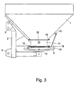
- Fig.4
- ein verschiebbar an dem Flanschelement angeordnetes Auslaufelement,
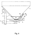
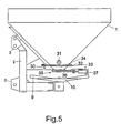
- Fig.5
- einen weiteren Schleuderdüngerstreuer in Seitenansicht,
- Fig.6
- den Schleuderdüngerstreuer in der Ansicht von hinten,
- Fig.7
- den Schleuderdüngerstreuer mit einem anderen Aus laufelement und Dosiereinrichtung in Seitenansicht und
- Fig.8
- den Schleuderdüngerstreuer gemäß Fig.7 in der Ansicht von hinten.
- Fig.1
- the centrifugal fertilizer spreader in the view from behind,
- Fig.2
- a discharge element arranged on the storage container for small to medium application rates,
- Figure 3
- a discharge element arranged on the storage container for application rates up to a very large amount,
- Figure 4
- a discharge element arranged displaceably on the flange element,
- Figure 5
- another centrifugal fertilizer spreader in side view,
- Figure 6
- the centrifugal fertilizer spreader in the view from behind,
- Figure 7
- the centrifugal fertilizer spreader with another from running element and metering device in side view and
- Figure 8
- the centrifugal fertilizer broadcaster according to Figure 7 in the view from behind.
Der Schleuderdüngerstreuer weist den Vorratsbehälter 1 auf.
Der Vorratsbehälter 1 ist an dem tragenden Rahmen 2 mit den
Dreipunktkupplungselementen 3 angeordnet. Der Vorratsbehälter
1 ist durch ein dachförmiges Mittelteil 4 in die beiden
Auslauftrichter 5 und 6 unterteilt. Die Auslauftrichter 5 und
6 gehen jeweils in ein Auslaßelement 7 über, dem jeweils ein
Dosierorgan 8 zugeordnet ist. Unterhalb der Dosierorgane 8
befinden sich die mit Wurfschaufeln 9 besetzten Schleuderscheiben
10, welche in einem entgegengesetzten Drehsinn
zueinander rotierend von einer Kraftquelle angetrieben werden. The centrifugal fertilizer spreader has the
Die Rührwellen 11 sind jeweils in den Auslaßelementen 7 und 8
gelagert.The stirring
Die Dosierorgane 9 weisen eine Bodenplatte 12 mit darin
angeordneten, jedoch nicht dargestellten Auslauföffnungen
auf, die über einen Schieber 13 in ihrer Öffnungsweite einstellbar
ist, wobei die Öffnungsstellung des Schiebers 13
über die mit dem Anschlagelement 14 zusammenwirkende Skala 15
einstellbar ist.The
Die Auslaufelemente 7 sind über die Flanschelemente 16 an den
unteren Enden der Auslauftrichter 5, 6 angeordnet. Die Auslaufelemente
7 mit den zugehörigen Dosierorganen 8 sind für
kleine bis mittlere Ausbringmengen vorgesehen. Die Größe der
Auslaufelemente 7 ist im Bereich der Auslauföffnung an die
Größe der Auslauföffnung angepaßt, so daß sich möglichst
kleine Restmengen ergeben. Die Auslaufelemente 7 sind aus
nichtrostendem Material, beispielsweise aus Kunststoffmaterial
oder Metallguß hergestellt.The
Wenn der Schleuderdüngerstreuer gemäß den Fig.1 und 2 für die
Ausbringung von großen Ausbringmengen, insbesondere wenn auch
große Arbeitsbreiten erreicht werden sollen, ausgestattet
werden soll, werden an den Flanschelementen 16 die in Fig.3
dargestellten Auslaufelemente 17 angeordnet. Diese Auslaufelemente
17 weisen Dosierorgane 18 mit größeren Auslauföffnungen
als die in den Auslaufelementen 7 in den Fig.1 und 2
befindlichen Auslauföffnungen auf. Somit sind die Dosierorgane
18 für die großen Ausbringmengen größer als die Dosierorgane
9 ausgelegt. Die Dosierorgane 18 der Auslaufelemente 17
weisen die in der Bodenplatte 19 angeordnete, jedoch nicht
dargestellte Auslauföffnung auf, die über den Schieber 20 in
ihrer Öffnungsweite einstellbar ist. Die Öffnungsstellung des
Schiebers 20 wird durch den Anschlag 21 bestimmt, der anhand
der Skala 15 einstellbar ist. Die Auslaufelemente 17 sind aus
nichtrostendem Material, insbesondere Kunststoffmaterial oder
Metallguß hergestellt. In der Seitenwand der Auslaufelemente
ist das Rührelement 22 gelagert.If the centrifugal fertilizer spreader according to Figures 1 and 2 for the
Application of large application rates, especially if so
large working widths are to be achieved
is to be on the
Wie aus der vorhergehenden Beschreibung anhand der Fig.1 und
3 entnehmbar ist, sind die Auslaufelemente 7 und 8 einerseits
und 17 andererseits gegeneinander austauschbar und wahlweise
an dem Flanschelement 16 entsprechend den Einsatzbedingung
anzuordnen bzw. der Düngerstreuer ist entsprechend den geforderten
Einsatzverhältnissen auszurüsten. Somit sind entsprechend
des vorgesehenen Ausbringmengenbereiches ausgelegte
Auslaßelemente 7, 8, 17 mit zugeordneten Dosierorganen 9, 18
in austauschbarer Weise vorgesehen.As is apparent from the preceding description with reference to FIGS
3 is removed, the
Weiterhin ist in einer weiteren Ausführungsform gemäß Fig.4
vorgesehen, daß das Flanschelement 23 zur Anordnung von
gegenüber dem Vorratsbehälter 1 bzw. der Schleuderscheibe 11
verschiebbares Auslaufelement 24 vorgesehen ist. Hierzu kann
entweder das Flanschelement 23 selbst mit Langlöchern, aufgrund
derer das Auslaufelement 24 verschiebbar ist, versehen
ist, oder an dem Flanschelement 23 ist eine Zwischenplatte
vorgesehen, in welcher die Schiebeführungen zur Verschiebung
des Auslaufelementes 24 gegenüber der Schleuderscheibe 11
angeordnet sind. Durch die Verschiebung des Auslaufelementes
24 mit den Dosierorganen 25 läßt sich der Aufbabepunkt des
Materials auf der Schleuderscheibe 11 verlagern. An dem
Auslaufelement 24 ist eine Skala 26 angeordnet, an welcher
die Öffnungsstellung des Schiebers 27 über die Mengeneinstellvorrichtung
28 für den Schieber 27 einstellbar ist. Die
Skala 26 und die Mengeneinstellvorrichtung 28 sind an einem
an dem Auslaufelement 24 nach oben ragenden Halteelement 29
angeordnet. Zur Verstellung des Auslaufelementes 24 gegenüber
der Schleuderscheibe 11 und dem Vorratsbehälter 1 ist ein
nicht dargestelltes Einstellelement, welches motorisch ausgebildet
oder angetrieben sein kann, zwischen dem Vorratsbehälter
1 und dem Auslaufelement 24 angeordnet.Furthermore, in a further embodiment according to FIG
provided that the
Der Schleuderdüngerstreuer gemäß den Fig.5 und 6 unterscheidet
sich von dem Schleuderdüngerstreuer gemäß den Fig.1 bis 4
durch eine andere Ausbildung des unteren Auslauftrichterbereiches
30. Bei diesem Ausführungsbeispiel ist die Rührwelle
31 oberhalb der Flanschstelle 32 im Vorratsbehälter 1 gelagert.
An dem Flanschelement 33 ist ein Austauschauslaufelement
34 mit einem Dosierorgan 35, dessen Schieber 36 über
eine als Elektromotor ausgebildete elektrische Betätigungseinrichtung
37 betätigbar ist.The centrifugal fertilizer spreader according to FIGS. 5 and 6 differs
from the centrifugal fertilizer spreader according to FIGS. 1 to 4
by another design of the lower
Bei dem Ausführungsbeispiel gemäß den Fig. 7 und 8 ist das
Austauschauslaufelement 34 mit dem Dosierorgan 34' gegen das
Austauschauslaufelement 38 mit dem mittels einer hydraulischen
Betätigungseinrichtung 39, die den Hydraulikzylinder 40
und die Zugfeder 41 aufweist, in austauschbarer Weise angeordnet.In the embodiment according to FIGS. 7 and 8, this is
Es sind noch weitere, nicht dargestellte Austauschauslaufelemente
mit anderen Betätigungseinrichtungen und Ansteuerungseinrichtungen
zur Anordnung an dem Flanschelement 33 des
Vorratsbehälters 1 vorgesehen. So kann beispielsweise die
Dosiereinrichtung mit einer elektronischen Ansteuerungsvorrichtung,
die mittels standortspezifische Ausbringung,
Steuerung und Regelung ausgerüstet ist, zusätzlich ausgerüstet
sein, und gegen das Austauschelement 38 oder 34 ausgetauscht
werden.There are still further, not shown Austauschauslaufelemente
with other controls and controls
for placement on the
An dem Flanschelement 33 sind somit Austauschauslaufelemente
mit verschiedenartig ausgebildeten Dosierorganen zur Anordnung
vorgesehen. Die Austauschauslaufelemente werden mit der
jeweiligen Dosiereinrichtung als ganzes lösbar an dem Anschlußelement
ausgebildeten Flanschelement 33 angeordnet und
gegen eine der Austauschauslaufelemente mit der jeweils
gewünschten Dosiereinrichtung ausgetauscht bzw. in austauschbarer
Weise befestigt.On the
Claims (14)
- Centrifugal fertiliser spreader, having at least one hopper, which is at least partially configured in the form of a funnel, at least one outlet member being disposed at the lower region of said hopper via at least one connecting member, a metering member being associated with said outlet member, characterised in that a plurality of interchangeable outlet members (7, 17, 24, 34, 38) are provided for disposition on the connecting member, said outlet members being in the form of discharge vessels and having differently configured metering members (18, 25, 35, 35').
- Centrifugal fertiliser spreader according to claim 1, characterised in that the interchangeable outlet members (7, 17, 24, 34, 38) are in the form ofand in that the interchangeable outlet members (7, 17, 24, 34, 38) are detachably disposed on the connecting member (16, 23, 33) as a whole with the respective metering means (18, 25, 35, 35') and are interchangeable with one of the above-mentioned interchangeable outlet members having the above-mentioned metering means.a metering means (35') having an hydraulic actuating means (39),
ora metering means (35) having an electrical actuating means (37),
ora metering means having an electronic actuating means, which is provided with a locus-specific distribution control and/or regulator, - Centrifugal fertiliser spreader according to one or more of the preceding claims, characterised in that the connecting member (33) is situated on the hopper (1) beneath the bearing surface of the agitating means (31).
- Centrifugal fertiliser spreader according to one or more of the preceding claims, characterised in that various outlet members (7, 17, 24, 34, 38), which are in the form of discharge vessels, are provided with associated metering members (18, 25, 35, 35') for disposition on the flange member (16, 23,33).
- Centrifugal fertiliser spreader according to claim 4, characterised in that outlet members (7, 17, 24), which are adapted to correspond to the envisaged output range, are provided with associated metering members (8, 18, 25) in an interchangeable manner.
- Centrifugal fertiliser spreader according to claim 4, the metering member being in the form of an outlet aperture disposed in a base member, the width of opening of said aperture being adjustable by a slide member which co-operates with the outlet aperture, characterised in that outlet members (7, 17, 24) are provided with variably large outlet apertures, the size of the outlet members (7, 17, 24) being adapted to the size of the outlet aperture, at least in the region of the outlet aperture.
- Centrifugal fertiliser spreader according to one or more of the preceding claims, characterised in that the outlet members (7, 17, 24) are produced from non-corrosive material, more especially from plastics material or cast metal.
- Centrifugal fertiliser spreader according to one or more of the preceding claims, characterised in that the metering member (8, 18, 25) has associated therewith an agitating member (11, 22) which is mounted in the lateral wall of the outlet member (7, 17, 24) and is interchangeable with the outlet member.
- Centrifugal fertiliser spreader according to one or more of the preceding claims, characterised in that the outlet member (24) is disposed on the flange member (23) so as to be displaceable relative to the centrifugal disc (10).
- Centrifugal fertiliser spreader according to one or more of the preceding claims, characterised in that a scale (26) is disposed on the outlet member (24), the open position of the slide (27) being adjustable on the basis of said scale.
- Centrifugal fertiliser spreader according to one or more of the preceding claims, characterised in that the quantity adjusting apparatus (28) for the slide (27) is disposed on the outlet member (24).
- Centrifugal fertiliser spreader according to one or more of the preceding claims, characterised in that an upwardly protruding retaining member (29) is disposed on the outlet member (24), the scale (26) and the quantity adjusting apparatus (28) being disposed on said retaining member.
- Centrifugal fertiliser spreader according to one or more of the preceding claims, characterised in that slidable guides are disposed in the flange plate (23) on the hopper (1) and/or on the outlet member (24).
- Centrifugal fertiliser spreader according to one or more of the preceding claims, characterised in that adjustment means are disposed between the hopper (1) and the outlet member (24).
Applications Claiming Priority (2)
| Application Number | Priority Date | Filing Date | Title |
|---|---|---|---|
| DE19939169 | 1999-08-20 | ||
| DE19939169A DE19939169A1 (en) | 1999-08-20 | 1999-08-20 | Centrifugal fertilizer spreader |
Publications (2)
| Publication Number | Publication Date |
|---|---|
| EP1078564A1 EP1078564A1 (en) | 2001-02-28 |
| EP1078564B1 true EP1078564B1 (en) | 2004-01-28 |
Family
ID=7918800
Family Applications (1)
| Application Number | Title | Priority Date | Filing Date |
|---|---|---|---|
| EP00117052A Expired - Lifetime EP1078564B1 (en) | 1999-08-20 | 2000-08-09 | Fertilizer broadcaster |
Country Status (3)
| Country | Link |
|---|---|
| EP (1) | EP1078564B1 (en) |
| DE (2) | DE19939169A1 (en) |
| DK (1) | DK1078564T3 (en) |
Families Citing this family (3)
| Publication number | Priority date | Publication date | Assignee | Title |
|---|---|---|---|---|
| DE102006019477A1 (en) * | 2006-04-26 | 2007-10-31 | Amazonen-Werke H. Dreyer Gmbh & Co. Kg | Device for sprinkling granular substances |
| DE102012024363A1 (en) * | 2012-12-13 | 2014-06-18 | Rauch Landmaschinenfabrik Gmbh | distributing |
| DE102016002827A1 (en) | 2016-03-09 | 2017-09-14 | Rauch Landmaschinenfabrik Gmbh | distributing |
Family Cites Families (4)
| Publication number | Priority date | Publication date | Assignee | Title |
|---|---|---|---|---|
| US3738546A (en) * | 1971-05-10 | 1973-06-12 | Cyclone Seeder Co | Metering device for securement to the hopper or container of a distributor of seeds and other fluent material |
| EP0192089B1 (en) * | 1985-02-06 | 1991-08-28 | Amazonen-Werke H. Dreyer GmbH & Co. KG | Broadcaster, especially for granulated fertilizer |
| NL8701870A (en) * | 1987-08-10 | 1989-03-01 | Lely Nv C Van Der | MACHINE FOR DISTRIBUTION OF EQUIPMENT. |
| DE4302802A1 (en) | 1993-02-02 | 1994-08-04 | Amazonen Werke Dreyer H | Agricultural dung spreading machine with spinning discs |
-
1999
- 1999-08-20 DE DE19939169A patent/DE19939169A1/en not_active Withdrawn
-
2000
- 2000-08-09 EP EP00117052A patent/EP1078564B1/en not_active Expired - Lifetime
- 2000-08-09 DK DK00117052T patent/DK1078564T3/en active
- 2000-08-09 DE DE50005123T patent/DE50005123D1/en not_active Expired - Lifetime
Also Published As
| Publication number | Publication date |
|---|---|
| DE19939169A1 (en) | 2001-02-22 |
| EP1078564A1 (en) | 2001-02-28 |
| DK1078564T3 (en) | 2004-03-08 |
| DE50005123D1 (en) | 2004-03-04 |
Similar Documents
| Publication | Publication Date | Title |
|---|---|---|
| EP0540889B2 (en) | Fertilizer broadcaster | |
| EP0820219B1 (en) | Centrifugal fertiliser spreader | |
| DE3641080C2 (en) | Centrifugal fertilizer spreader | |
| EP1078564B1 (en) | Fertilizer broadcaster | |
| DE4134315A1 (en) | Centrifugal manure spreader - has two delivery chutes over rotating disks driven by gearbox with adjustable position of discharge onto disks | |
| EP0410112A1 (en) | Centrifugal spreader for pourable material, especially fertilizer | |
| EP0951814B1 (en) | Broadcaster | |
| DE3616538C2 (en) | ||
| EP0386540B1 (en) | System for making a series broadcaster | |
| DE4302802A1 (en) | Agricultural dung spreading machine with spinning discs | |
| EP0356770B1 (en) | Spinning fertilizer distributors | |
| EP0613613A1 (en) | Broadcaster | |
| DE4134317C2 (en) | Centrifugal fertilizer spreader | |
| DE19829782A1 (en) | Agricultural manure spreader with counter-rotating disks | |
| DE1924631C3 (en) | Spreader | |
| DE10033674A1 (en) | Centrifugal manure spreader has revolution rate adjustment devices arranged in centrifugal plate drive and centrifugal plates can be rotated at different speeds | |
| DE19745441A1 (en) | Centrifugal spreader | |
| DD297905A5 (en) | SCHLEUDERDUENGERSTREUER | |
| DD295966A5 (en) | Centrifugal | |
| DE19606586A1 (en) | Centrifugal fertilizer spreader | |
| DE19802658A1 (en) | Distributing machine with function control and blockage protection | |
| DE19748838A1 (en) | Centrifugal spreader | |
| DE19742440A1 (en) | Centrifugal spreader | |
| DE19714935A1 (en) | Fertiliser spreader with at least two storage containers | |
| DE3903967A1 (en) | AGRICULTURAL DISTRIBUTION MACHINE |
Legal Events
| Date | Code | Title | Description |
|---|---|---|---|
| PUAI | Public reference made under article 153(3) epc to a published international application that has entered the european phase |
Free format text: ORIGINAL CODE: 0009012 |
|
| AK | Designated contracting states |
Kind code of ref document: A1 Designated state(s): DE DK FR NL |
|
| AX | Request for extension of the european patent |
Free format text: AL;LT;LV;MK;RO;SI |
|
| 17P | Request for examination filed |
Effective date: 20010510 |
|
| AKX | Designation fees paid |
Free format text: DE DK FR NL |
|
| 17Q | First examination report despatched |
Effective date: 20030221 |
|
| GRAP | Despatch of communication of intention to grant a patent |
Free format text: ORIGINAL CODE: EPIDOSNIGR1 |
|
| GRAS | Grant fee paid |
Free format text: ORIGINAL CODE: EPIDOSNIGR3 |
|
| GRAA | (expected) grant |
Free format text: ORIGINAL CODE: 0009210 |
|
| AK | Designated contracting states |
Kind code of ref document: B1 Designated state(s): DE DK FR NL |
|
| REF | Corresponds to: |
Ref document number: 50005123 Country of ref document: DE Date of ref document: 20040304 Kind code of ref document: P |
|
| REG | Reference to a national code |
Ref country code: DK Ref legal event code: T3 |
|
| ET | Fr: translation filed | ||
| PLBE | No opposition filed within time limit |
Free format text: ORIGINAL CODE: 0009261 |
|
| STAA | Information on the status of an ep patent application or granted ep patent |
Free format text: STATUS: NO OPPOSITION FILED WITHIN TIME LIMIT |
|
| 26N | No opposition filed |
Effective date: 20041029 |
|
| REG | Reference to a national code |
Ref country code: FR Ref legal event code: PLFP Year of fee payment: 17 |
|
| REG | Reference to a national code |
Ref country code: FR Ref legal event code: PLFP Year of fee payment: 18 |
|
| REG | Reference to a national code |
Ref country code: FR Ref legal event code: PLFP Year of fee payment: 19 |
|
| PGFP | Annual fee paid to national office [announced via postgrant information from national office to epo] |
Ref country code: NL Payment date: 20190814 Year of fee payment: 20 |
|
| PGFP | Annual fee paid to national office [announced via postgrant information from national office to epo] |
Ref country code: FR Payment date: 20190711 Year of fee payment: 20 Ref country code: DE Payment date: 20190730 Year of fee payment: 20 Ref country code: DK Payment date: 20190813 Year of fee payment: 20 |
|
| REG | Reference to a national code |
Ref country code: DE Ref legal event code: R071 Ref document number: 50005123 Country of ref document: DE |
|
| REG | Reference to a national code |
Ref country code: DK Ref legal event code: EUP Expiry date: 20200809 |
|
| REG | Reference to a national code |
Ref country code: NL Ref legal event code: MK Effective date: 20200808 |