EP1077786B1 - Non-nodal mounting system for ultrasonic apparatus - Google Patents
Non-nodal mounting system for ultrasonic apparatus Download PDFInfo
- Publication number
- EP1077786B1 EP1077786B1 EP99920347A EP99920347A EP1077786B1 EP 1077786 B1 EP1077786 B1 EP 1077786B1 EP 99920347 A EP99920347 A EP 99920347A EP 99920347 A EP99920347 A EP 99920347A EP 1077786 B1 EP1077786 B1 EP 1077786B1
- Authority
- EP
- European Patent Office
- Prior art keywords
- horn
- mounting system
- ultrasonic
- nodal
- fingers
- Prior art date
- Legal status (The legal status is an assumption and is not a legal conclusion. Google has not performed a legal analysis and makes no representation as to the accuracy of the status listed.)
- Expired - Lifetime
Links
Images


Classifications
-
- B—PERFORMING OPERATIONS; TRANSPORTING
- B23—MACHINE TOOLS; METAL-WORKING NOT OTHERWISE PROVIDED FOR
- B23K—SOLDERING OR UNSOLDERING; WELDING; CLADDING OR PLATING BY SOLDERING OR WELDING; CUTTING BY APPLYING HEAT LOCALLY, e.g. FLAME CUTTING; WORKING BY LASER BEAM
- B23K20/00—Non-electric welding by applying impact or other pressure, with or without the application of heat, e.g. cladding or plating
- B23K20/10—Non-electric welding by applying impact or other pressure, with or without the application of heat, e.g. cladding or plating making use of vibrations, e.g. ultrasonic welding
-
- B—PERFORMING OPERATIONS; TRANSPORTING
- B06—GENERATING OR TRANSMITTING MECHANICAL VIBRATIONS IN GENERAL
- B06B—METHODS OR APPARATUS FOR GENERATING OR TRANSMITTING MECHANICAL VIBRATIONS OF INFRASONIC, SONIC, OR ULTRASONIC FREQUENCY, e.g. FOR PERFORMING MECHANICAL WORK IN GENERAL
- B06B3/00—Methods or apparatus specially adapted for transmitting mechanical vibrations of infrasonic, sonic, or ultrasonic frequency
-
- B—PERFORMING OPERATIONS; TRANSPORTING
- B29—WORKING OF PLASTICS; WORKING OF SUBSTANCES IN A PLASTIC STATE IN GENERAL
- B29C—SHAPING OR JOINING OF PLASTICS; SHAPING OF MATERIAL IN A PLASTIC STATE, NOT OTHERWISE PROVIDED FOR; AFTER-TREATMENT OF THE SHAPED PRODUCTS, e.g. REPAIRING
- B29C65/00—Joining or sealing of preformed parts, e.g. welding of plastics materials; Apparatus therefor
- B29C65/02—Joining or sealing of preformed parts, e.g. welding of plastics materials; Apparatus therefor by heating, with or without pressure
- B29C65/08—Joining or sealing of preformed parts, e.g. welding of plastics materials; Apparatus therefor by heating, with or without pressure using ultrasonic vibrations
- B29C65/083—Joining or sealing of preformed parts, e.g. welding of plastics materials; Apparatus therefor by heating, with or without pressure using ultrasonic vibrations using a rotary sonotrode or a rotary anvil
- B29C65/085—Joining or sealing of preformed parts, e.g. welding of plastics materials; Apparatus therefor by heating, with or without pressure using ultrasonic vibrations using a rotary sonotrode or a rotary anvil using a rotary sonotrode
-
- B—PERFORMING OPERATIONS; TRANSPORTING
- B29—WORKING OF PLASTICS; WORKING OF SUBSTANCES IN A PLASTIC STATE IN GENERAL
- B29C—SHAPING OR JOINING OF PLASTICS; SHAPING OF MATERIAL IN A PLASTIC STATE, NOT OTHERWISE PROVIDED FOR; AFTER-TREATMENT OF THE SHAPED PRODUCTS, e.g. REPAIRING
- B29C66/00—General aspects of processes or apparatus for joining preformed parts
- B29C66/80—General aspects of machine operations or constructions and parts thereof
- B29C66/81—General aspects of the pressing elements, i.e. the elements applying pressure on the parts to be joined in the area to be joined, e.g. the welding jaws or clamps
- B29C66/816—General aspects of the pressing elements, i.e. the elements applying pressure on the parts to be joined in the area to be joined, e.g. the welding jaws or clamps characterised by the mounting of the pressing elements, e.g. of the welding jaws or clamps
-
- B—PERFORMING OPERATIONS; TRANSPORTING
- B29—WORKING OF PLASTICS; WORKING OF SUBSTANCES IN A PLASTIC STATE IN GENERAL
- B29C—SHAPING OR JOINING OF PLASTICS; SHAPING OF MATERIAL IN A PLASTIC STATE, NOT OTHERWISE PROVIDED FOR; AFTER-TREATMENT OF THE SHAPED PRODUCTS, e.g. REPAIRING
- B29C66/00—General aspects of processes or apparatus for joining preformed parts
- B29C66/80—General aspects of machine operations or constructions and parts thereof
- B29C66/83—General aspects of machine operations or constructions and parts thereof characterised by the movement of the joining or pressing tools
- B29C66/834—General aspects of machine operations or constructions and parts thereof characterised by the movement of the joining or pressing tools moving with the parts to be joined
- B29C66/8341—Roller, cylinder or drum types; Band or belt types; Ball types
- B29C66/83411—Roller, cylinder or drum types
- B29C66/83413—Roller, cylinder or drum types cooperating rollers, cylinders or drums
Definitions
- the present invention relates to acoustic horns. More particularly, the present invention relates to non-nodal mounting systems for ultrasonic apparatus.
- acoustic welding such as ultrasonic welding
- two parts to be joined are placed directly below an ultrasonic horn.
- the horn plunges (travels toward the parts) and transmits ultrasonic vibrations into the top part.
- the vibrations travel through the top part to the interface of the two parts.
- the vibrational energy is converted to heat due to intermolecular friction that melts and fuses the two parts.
- the vibrations stop the two parts solidify under force, producing a weld at the joining surface.
- Continuous ultrasonic welding is typically used for sealing fabrics, films, and other parts.
- the ultrasonic horn is stationary and the part is moved beneath it.
- Scan welding is a type of continuous welding in which the part moves. The plastic part is scanned beneath one or more stationary horns. In transverse welding, the part is stationary while the horn moves over it.
- the horn is an acoustical tool made of, for example, aluminum, titanium, or sintered steel that transfers the mechanical vibratory energy to the part.
- Horn displacement or amplitude is the peak-to-peak movement of the horn face.
- the ratio of horn output amplitude to the horn input amplitude is termed gain.
- Gain is a function of the ratio of the mass of the horn at the vibration input and output sections. Generally, in horns, the direction of amplitude at the welding surface of the horn is coincident with the direction of the applied mechanical vibrations.
- a rotary acoustic horn like all horns, imparts energy at a selected wavelength, frequency, and amplitude.
- the rotary horn includes a shaft with input and output ends, and a welding portion mounted on and coaxial with the output end.
- the diameter of the welding portion is greater than the diameter of the shaft.
- the welding portion has a cylindrical weld face having a diameter that expands and contracts with the application of acoustic energy.
- a rotary horn is cylindrical and rotates around a longitudinal axis.
- the input vibration is in the axial direction and the output vibration is in the radial direction.
- the horn and anvil are close to each other, and the anvil can rotate in the opposite direction to the horn.
- the part to be bonded passes between these cylindrical surfaces at a linear velocity which equals the tangential velocity of these cylindrical surfaces.
- Matching the tangential velocities of the horn and the anvil with the linear velocity of the material is intended to minimize the drag between the horn and the material.
- the excitation in the axial direction is similar to that in conventional plunge welding.
- U.S. Patent No. 5,096,532 describes two classes of rotary horn.
- the patent compares a commercially available full wavelength rotary horn, manufactured by Mecasonic-KLN, Inc. of Fullerton, California (Mecasonic horn) and a half wavelength rotary horn described in the '532 patent.
- U.S. Patent No. 5,707,483 discloses another type of rotary acoustic horn with undercuts.
- a node is a portion of the horn that is not moving in one or more directions. With a nodal mount the horn can be held or grasped rigidly. Non-nodal mounts require some flexible elements because the horn surface is moving (vibrating). Because of the difficulties of handling the vibrations, non-nodal mounts are typically not used in the industry.
- Nodal mounts typically have a flange machined at a node, shown in Figure 1, or a series of set-screws positioned radially around the node shown in Figure 2.
- U.S. Patent No. 4,647,336 discloses a reparable nodal flange mount such as that of Figure 1. In this design the flange at the nodal point of a booster has an O-ring above and below it. A two piece support collar clamps against the O-rings to support the assembly. (This is shown in Figure 4 of the '336 patent).
- U.S. Patent No. 4,995,938 discloses using the nodal flanges as pistons of an air or hydraulic cylinder. In this system, the method of supporting the booster and the method of applying the required welding force are combined, as shown in Figure 1 of the '938 patent).
- U.S. Patent No. 5,486,733 discloses a nodal mount inside the converter. A machined ring is sandwiched between the piezoelectric crystals that are driving the horn.
- U.S. Patent No. 4,975,133 includes a set-screw nodal mount for an ultrasonic booster. This design is used for rotary shear welding operation.
- RD 21128 discloses a method where a potting material is used instead of O-rings on a nodal flange type mounting.
- Anti-nodes are areas of maximum displacement of a horn or booster. Attaching mounting systems at these locations or at other non-nodal locations requires the mount to be designed to isolate the vibration from base of the device.
- U.S. Patent No. 3,752,380 discloses using a pair of leaf springs located at the non-nodes of a non-rotating bar horn.
- U.S. Patent No. 3,863,826 discloses a sonic or ultrasonic apparatus that uses a leaf spring support to mount a converter to a stationary support. These springs isolate the vibration and allow vertical motion with an air cylinder to accommodate the height of the parts being welded. This design is for a non-rotating horn. In both these patents, the leaf spring is sandwiched between the junction of the converter or booster and the horn. This interferes with the transmission of ultrasonic energy through the horn and limits the usefulness of rotary horns.
- U.S. Patent No. 3,955,740 discloses a non-nodal rotary horn mount which uses a solid metal diaphragm located in the junction between the booster and horn.
- the diaphragm is statically stiff, having a static stiffness of about 1.35x10 7 N/m (77,000 lb/in). Very high static loads are possible because the design uses a rotating tube to isolate this force from the bearings Also, in this design, the diaphragm is designed to resonate at the frequency of the horn.
- the diaphragm is an ultrasonic element.
- U.S. Patent No. 4,884,334 discloses a statically stiff disk or finger support which resonates at the frequency of the horn and is an ultrasonic element.
- U.S. Patent No. 5,468,336 discloses a flexural spring support for a shear welding apparatus. This design uses tapered support beams that allow a plate to be vibrated side-to-side while remaining parallel to the fixed plate. This side-to-side motion slides the parts being welded past each other and welds them together. This design is for a shear welding operation, uses taper beams, and could not be practically adapted to a rotary horn mounting situation.
- U.S. Patent No. 5,464,498 discloses another flexural support spring method. This design is machined from a single piece of material.
- a commercially available non-nodal mount for horns shown in Figure 3, was manufactured by American Technology, Inc. (Amtech), Shelton, CT, and is used for shear welding.
- This unit has a plate with slots machined radially from the outer diameter to create fingers. The outer edge of the finger plate is mounted with a clamp ring while the inner fingers are clamped between the end of the horn and the booster.
- a non-nodal mounting system for an ultrasonic element is defined in claim 1.
- the means for reducing the force can include fingers shaped to reduce.the force transmitted to the drive ring or a solid circular disk of uniform or nonuniform thickness.
- the fingers can be long and slender, and have a length-to-width ratio of from 2 through 10, and a width-to-thickness ratio of from 2 through 20.
- the flexible disk can also include an inner annular ring at the radially inner portion and a concentric outer annular ring at the radially outer portion which are connected by the fingers.
- An inner clamp ring can be connected to the inner annular ring and an outer clamp ring can be connected to the inner annular ring of the flexible disk.
- the ultrasonic element can also be a rotary horn.
- the mounting system can also include means for damping vibrations.
- This means can include high damping metals located between the flexible disk and the clamp ring and between the flexible disk and one of the ultrasonic element and drive ring.
- the high damping metals can be copper or lead.
- the mounting system can also include a rotationally fixed mounting housing.
- Figure 1 is a side view, partially in section, of a known horn mount.
- Figure 2 is a cross-sectional view of another known horn mount.
- Figure 3 is a perspective view of another known horn mount.
- Figure 4 is a cross-sectional view of the horn mounting system according to one embodiment of the invention showing the drive end of the horn.
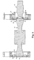
- Figure 5 is a cross-sectional view of the mounting system of Figure 4 showing the entire horn.
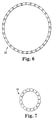
- Figure 6 is a top view of an inner clamp ring used in the mount of Figure 4.
- Figure 7 is a top view of an outer clamp ring used in the mount of Figure 4.
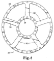
- Figure 8 is a top view of a flex finger disk used in the mount of Figure 4.
- Figures 9a, 9b, and 9c are schematic views of the wave shape of the fingers for different numbers of nodes.
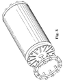
- Figure 10 is a perspective view of the horn of Figure 4.
- the invention is a non-nodal mounting system for an ultrasonic element.
- Non-nodal means any location that is not a node, including anti-nodes.
- An ultrasonic element is a part with a desired resonant (also known as operating) frequency that is driven at that resonant frequency.
- Ultrasonic elements include converters, which are power excitation devices; boosters, which modify the amplitude of a converter; and ultrasonic horns, such as rotary ultrasonic horns, which is the welding tooling that contacts a workpiece and can modify the amplitude from a converter.
- Other ultrasonic elements include horn support members that have a natural frequency near the operating frequency of the horn.
- the mounting system includes a flexible fingered member.
- This member is shown and described as a circular disk. Especially for non-rotary horns, this flexible member can be other shapes. Because the disk does not resonate at the operating frequency of the horn, it is not an ultrasonic element. (It is fixed to an ultrasonic element, does not resonate, yet does not break!)
- the disk isolates the displacement of the horn (0.0025-0.0051 cm (0.001-0.002 in) at the horn's operating frequency, which in the illustrated embodiments is 20,000 Hz) from the support frame.
- the invention can be used to non-nodally mount any ultrasonic element.
- the non-nodal mounting system can be located at one or both ends of any ultrasonic element or at any location that does not interfere with the welding process.
- Figures 4, 5, and 10 show a rotary ultrasonic horn 10 and booster 12 with a mounting system 14.
- Figure 4 shows the drive end of the horn.
- the mounting system 14 includes a non-rotating mounting housing 16, an inner clamp ring 18 (see Figure 6), an outer clamp ring 20 (see Figure 7), and a drive ring 22.
- the drive ring 22 is driven to rotate the horn 10 during operation.
- the mounting system 14 also can transmit torque to the horn.
- a flex finger disk 24 can include inner and outer concentric annular rings 26, 28 that are connected with five fingers 30, as shown in Figure 8. Any number of fingers 30 can be used.
- the fingers 30 can be rectangular, parallelepipedal, cylindrical, straight, curved, angular, or any other shape.
- the booster 12 is connected to the horn 10 through the use of a threaded stud 32 in a known manner.
- the flex finger disk 24 is attached to the horn 10.
- the inner clamp ring 18 is placed onto the flex finger disk 24, and the flex finger disk 24 and the inner clamp ring 18 are fastened to the horn 10 using sixteen #6-32 socket head cap screws 36.
- the screws can be less than 1.27 cm (0.5 in) apart.
- the drive ring 22 is placed on the flex finger disk 24.
- a bore on the drive ring locates the outer diameter of the flex finger disk 24.
- the outer clamp ring 20 is placed on the disk 24.
- Thirty-two #6-32 socket head cap screws 34 are used to fasten the outer clamp ring 20, flex finger disk 24, and drive ring 22 together.
- Bearings 40 are placed onto the drive ring and the mounting housing is placed on the drive ring.
- the mounting housing 16 does not rotate.
- the drive ring provides a point where a timing belt sprocket 38, shown in Figure 5, can be attached to rotate the horn 10.
- the non-drive end of the horn 10 is the same except that there is no drive point.
- the inner and outer clamp rings 18,20 are used to hold the flex finger disk 24 firmly to the horn 10 and the drive ring 22. They are connected to the inner annular ring 26 and the outer annular ring 28 of the flexible disk 24. As shown, the connection is accomplished using screws. This ensures that all of the parts of the disk are in firm contact with the housing 16, prevents sliding motion in the joint, and prevents heating of the flex finger disk 24. This connection could be made in any other known fashion, and these elements could be formed integrally as one piece. If these rings are not stiff enough, then the disk 24 will vibrate between the screws and the mounting will fail.
- the flex finger disk 24 is not sandwiched between the horn 10 and the booster 12 as is done in known non-nodal mounts. When the flex finger disk 24 is placed between the horn 10 and the booster 12 it affects the transmission of ultrasonic vibrations and limits the amplitude of the system. This problem is eliminated with the present invention. Also, the inner bore of the flex finger disk 24 fits over a pilot (round protrusion) on the horn 10. This locates the horn 10 radially allowing quick replacement on the horn.
- the width, thickness and length of the fingers 30 on the flex finger disk 24 are selected to achieve the following features, and depend on the amplitude and diameter of the drive ring 22.
- the fingers 30 can be long and slender, and have a length-to-width ratio of from 2 through 10, such as from 2 through 5.
- the fingers 30 have a width-to-thickness ratio of from 2 through 20, such as from 6 through 10.
- the fingers 30 do not have a natural frequency of vibration at or near the resonant frequency of the horn 10. In the current design 20,000 Hz is midway between two natural frequencies of the finger 30.
- the fingers 30 are as thin as possible. In one embodiment they are 0.157 cm (0.062 in) thick. This provides vibration isolation between the horn 10 and the mounting 14. Also, the fingers 30 need to be thick enough to handle the horn/anvil contact forces of up to 2700 N (500 lb).
- the maximum stress in the fingers 30 is below endurance limit for the material.
- the stress in the fingers 30 is based on the amplitude of the horn 10 and the wave shape in the fingers 30 (see Figure 9).
- a simple design of the flex fingers 30 would have a wave shape with zero nodes.
- the stress in the part can be found using textbook solutions for a beam. (The known non-nodal mounts used zero nodes.)
- the zero node design is very stiff and transmits excessive displacements back to the mounting.
- Making the disk 30 thinner results in better vibration isolation and increases the number of wave nodes.
- the radius of curvature of the finger between the nodes decreases.
- the stress in the fingers rises.
- the present invention has two nodes. This is a good compromise between isolation and stress in the fingers and differs from the known systems.
- This design has numerous advantages. It has a high radial stiffness. This is required so that high forces (greater than 2700N (500 lbs.)) can be applied between the horn 10 and the anvil roll (not shown). It has a low static stiffness of 9.98x10 5 N/m (5700 lb/in); sufficiently low for the bearings to handle the static flexible finger load without failure and without a rotating tube (as used in U.S. Patent No. 3,955,740). It has controlled horn location. The runout of the horn is controlled by machined components, not adjustment of the mounting. Also, the disk is attached directly to the horn without using elastomeric materials. Elastomeric materials would reduce the radial stiffness of the mounting, make runout control difficult, and absorb energy from the horn vibration, heating and degrading the elastomeric material.
- this design allows the horn to be supported on both ends. This dramatically reduces the deflection of the horn relative to a cantilevered mounting, allows the weld surface of the horn to be controlled and remain flat, and allows very high applied loads. Also, the flexible finger disk is not between the horn-booster junction. This avoids interference with the wave front translating across the horn-booster junction. With horns that have a small tuning window, the interference of the fingers with the ultrasonic waves prevents operation of the horn. This is especially true for the higher amplitudes that are required and the higher mass horns.
- the flexible fingers must not have a natural resonating frequency near the resonant frequency of the horn. Though the fingers could have any shape, keeping them rectangular allows the use of reference books to find the natural frequencies of the fingers. Finite element analysis (FEA) could be used for other designs.
- FEA Finite element analysis
- the vibration of the horn generates a forced vibration on one end of the fingers.
- This motion sends a transverse flexural wave down the fingers much like one would get by shaking the end of a string.
- the wave shape of the fingers determines the minimum bending radius and therefore the maximum stress in the fingers.
- the wave shape of the fingers is determined by the material and dimensions of the fingers.
- Figure 9 shows the first few possible configurations. The wave shape can be found using FEA or analytical solutions.
- the stress in the fingers must be below the fatigue limit of the material. Though any material may be used, alloy steel is currently used.
- the illustrated embodiment uses a flexible disk with fingers. This simplifies the analytical portion of the design but is not required.
- a solid disk, without fingers can support the horn.
- damping can be added to the junction between the flex disk and clamp ring and flex disk and drive ring or horn. These materials improve the clamping between the disk and other components. Also, the high damping of these materials further reduces vibration transfers to the ground and reduces the heat build up at the mounting. Damping materials include soft metals, such as annealed soft copper and lead, and elastomers.
- the disk itself either the entire disk or only the fingers for example, can be make of a high damping material.
- the mount of the present invention improves upon the designs in U.S. Patent Nos. 3,752,380 and 3,863,826.
- the invention is usable with rotating horns and the mount is not between the converter and the horn. Thus, there is no interference with the transmission of the energy through the horn.
- the mount of the present invention improves upon the design in U.S. Patent No. 5,468,336 in that the invention is usable with rotating horns and has uniform thickness fingers.
- the mount of the present invention improves upon Amtech mounts (shown in Figure 3) in several ways.
- the Amtech design has short (1.27 cm (0.5 in)), thick (0.15 cm (0.06 in)) fingers. This limits the maximum vibration amplitude that the fingers can handle without fatigue failure and transmits higher forces to the fixed members.
- the invention has fingers that are 3.7 cm (1.45 in) long, 1.27 cm (0.5 in) wide, and 0.16 cm (0.06 in) thick, and has been tested with vibration displacements of 0.005 cm (0.002 in).
- the fingers in the Amtech design are clamped between the horn and the booster. This interferes with the wave front translation across the horn-booster junction.
- the Amtech design has an even number of fingers.
- Opposing fingers of the appropriate length can form a simple bar horn which can start resonating at the resonant frequency of the horn. With a fixed outer diameter, this causes large power consumption and very short finger or mounting life (under 60 seconds).
- the Amtech design is used for a non-rotating booster and the horn is cantilevered.
Landscapes
- Engineering & Computer Science (AREA)
- Mechanical Engineering (AREA)
- Apparatuses For Generation Of Mechanical Vibrations (AREA)
- Lining Or Joining Of Plastics Or The Like (AREA)
Applications Claiming Priority (3)
| Application Number | Priority Date | Filing Date | Title |
|---|---|---|---|
| US79609 | 1998-05-15 | ||
| US09/079,609 US5976316A (en) | 1998-05-15 | 1998-05-15 | Non-nodal mounting system for acoustic horn |
| PCT/US1999/009821 WO1999059760A1 (en) | 1998-05-15 | 1999-05-05 | Non-nodal mounting system for acoustic horn |
Publications (2)
| Publication Number | Publication Date |
|---|---|
| EP1077786A1 EP1077786A1 (en) | 2001-02-28 |
| EP1077786B1 true EP1077786B1 (en) | 2003-11-26 |
Family
ID=22151627
Family Applications (1)
| Application Number | Title | Priority Date | Filing Date |
|---|---|---|---|
| EP99920347A Expired - Lifetime EP1077786B1 (en) | 1998-05-15 | 1999-05-05 | Non-nodal mounting system for ultrasonic apparatus |
Country Status (10)
| Country | Link |
|---|---|
| US (1) | US5976316A (enExample) |
| EP (1) | EP1077786B1 (enExample) |
| JP (1) | JP2002515335A (enExample) |
| KR (1) | KR100562246B1 (enExample) |
| AU (1) | AU3786599A (enExample) |
| BR (1) | BR9910464B1 (enExample) |
| CA (1) | CA2331729A1 (enExample) |
| DE (1) | DE69913124T2 (enExample) |
| TW (1) | TW422771B (enExample) |
| WO (1) | WO1999059760A1 (enExample) |
Families Citing this family (46)
| Publication number | Priority date | Publication date | Assignee | Title |
|---|---|---|---|---|
| FR2809984B1 (fr) * | 2000-06-09 | 2006-07-14 | Aplix Sa | Sonotrode rotative permettant de souder en continu sur une grande largeur |
| US6457626B1 (en) * | 2001-01-29 | 2002-10-01 | Branson Ultrasonics Corporation | Symmetric ultrasonic rotary horn |
| US6469418B1 (en) * | 2001-06-27 | 2002-10-22 | Scitex Digital Printing, Inc. | Vibration monitoring system and method |
| US6634539B2 (en) * | 2001-09-21 | 2003-10-21 | 3M Innovative Properties Company | Adjustable-gap rotary ultrasonic horn mounting apparatus and method for mounting |
| US6547903B1 (en) * | 2001-12-18 | 2003-04-15 | Kimberly-Clark Worldwide, Inc. | Rotary ultrasonic bonder or processor capable of high speed intermittent processing |
| US6620270B2 (en) | 2001-12-18 | 2003-09-16 | Kimberly-Clark Worldwide, Inc. | Control of processing force and process gap in rigid rotary ultrasonic systems |
| US6537403B1 (en) | 2001-12-18 | 2003-03-25 | Kimberly-Clark Worldwide, Inc. | Nip adjustment for a rigid ultrasonic bonder or processor |
| US6676003B2 (en) | 2001-12-18 | 2004-01-13 | Kimberly-Clark Worldwide, Inc. | Rigid isolation of rotary ultrasonic horn |
| US6613171B2 (en) * | 2001-12-18 | 2003-09-02 | Kimberly-Clark Worldwide, Inc. | Rotary ultrasonic bonder or processor capable of fixed gap operation |
| US7243894B2 (en) * | 2002-02-15 | 2007-07-17 | 3M Innovative Properties Company | Mount for vibratory elements |
| US6841921B2 (en) * | 2002-11-04 | 2005-01-11 | Kimberly-Clark Worldwide, Inc. | Ultrasonic horn assembly stack component connector |
| US6786383B2 (en) * | 2002-11-14 | 2004-09-07 | Kimberly-Clark Worldwide, Inc. | Ultrasonic horn assembly with fused stack components |
| US6758925B1 (en) * | 2002-12-20 | 2004-07-06 | Kimberly-Clark Worldwide, Inc. | Acoustical energy transfer component |
| US6767420B2 (en) * | 2002-12-20 | 2004-07-27 | Kimberly-Clark Worldwide, Inc. | Ultrasonic horn with isotropic breathing characteristics |
| US7297238B2 (en) * | 2003-03-31 | 2007-11-20 | 3M Innovative Properties Company | Ultrasonic energy system and method including a ceramic horn |
| US6786384B1 (en) | 2003-06-13 | 2004-09-07 | 3M Innovative Properties Company | Ultrasonic horn mount |
| EP1514670B1 (de) | 2003-08-13 | 2008-05-14 | Herrmann Ultraschalltechnik GmbH & Co. KG | Vorrichtung zum kontinuierlichen Verbinden und/oder Verfestigen von Materialbahnen mittels Ultraschall |
| WO2006074116A1 (en) * | 2005-01-03 | 2006-07-13 | 3M Innovative Properties Company | An elastic laminate material, and method of making |
| US7775413B2 (en) * | 2005-01-03 | 2010-08-17 | 3M Innovative Properties Company | Cantilevered bar gap adjustment for an ultrasonic welding system |
| US7769551B2 (en) * | 2005-01-03 | 2010-08-03 | 3M Innovative Properties Company | Method and system for determining a gap between a vibrational body and fixed point |
| US7828192B2 (en) * | 2005-01-03 | 2010-11-09 | 3M Innovative Properties Company | Amplitude adjustment of an ultrasonic horn |
| DK1866104T3 (da) * | 2005-03-23 | 2013-10-28 | 3L Ludvigsen As | Roterende ultralydsforsegler |
| DE102005063230B3 (de) | 2005-12-23 | 2007-07-05 | Herrmann Ultraschalltechnik Gmbh & Co. Kg | Vorrichtung zum Ultraschallbearbeiten eines Werkstücks |
| US20100276061A1 (en) * | 2005-12-30 | 2010-11-04 | 3M Innovative Properties Company | Cantilevered bar gap adjustment for an ultrasonic welding system |
| DE102006005734A1 (de) * | 2006-02-07 | 2007-08-09 | Bhs Corrugated Maschinen- Und Anlagenbau Gmbh | Ultraschall-Verbindungsvorrichtung und Verfahren zum Verbinden von Materialbahnen |
| WO2008037256A2 (en) * | 2006-09-28 | 2008-04-03 | 3L-Ludvigsen A/S | Rotary ultrasonic sealer |
| DE102008002744A1 (de) * | 2008-06-27 | 2009-12-31 | Herrmann Ultraschalltechnik Gmbh & Co. Kg | Ultraschallschwingeinheit mit Halterung |
| US8113258B2 (en) * | 2008-07-08 | 2012-02-14 | Sonics & Materials Inc. | Ultrasonic welding device |
| JP5491081B2 (ja) * | 2009-06-22 | 2014-05-14 | 株式会社アルテクス | 超音波振動金属接合用共振器 |
| US8082966B2 (en) | 2010-03-12 | 2011-12-27 | Edison Welding Institute, Inc. | System for enhancing sonotrode performance in ultrasonic additive manufacturing applications |
| WO2011137171A1 (en) | 2010-04-29 | 2011-11-03 | Edison Welding Institute, Inc. | Ultrasonic machining assembly for use with portable devices |
| DE102010029395A1 (de) * | 2010-05-07 | 2011-11-10 | Telsonic Holding Ag | Torsionssonotrode, Ultraschall-Schweißvorrichtung und Verfahren zur Herstellung einer Schweißverbindung mittels Ultraschall |
| US8409383B1 (en) * | 2011-09-30 | 2013-04-02 | GM Global Technology Operations LLC | Passively damped vibration welding system and method |
| US8950458B2 (en) | 2012-04-27 | 2015-02-10 | Sonics & Materials Inc. | System and method for mounting ultrasonic tools |
| DE102013100474A1 (de) * | 2013-01-17 | 2014-07-17 | Herrmann Ultraschalltechnik Gmbh & Co. Kg | Ultraschallschweißvorrichtung mit schwingungsentkoppeltem Gegenwerkzeug |
| JP6559006B2 (ja) * | 2015-08-06 | 2019-08-14 | ブランソン・ウルトラソニックス・コーポレーション | 超音波振動伝達機構部の保持構造 |
| EP3269492A1 (de) * | 2016-07-15 | 2018-01-17 | Telsonic Holding AG | Vorrichtung zum ultraschallschweissen und sonotrode für eine solche vorrichtung |
| DE212017000184U1 (de) * | 2016-07-15 | 2019-02-19 | Telsonic Holding Ag | Vorrichtung zum Ultraschallschweißen und Sonotrode für eine solche Vorrichtung |
| BR112020003831B1 (pt) | 2017-08-25 | 2023-03-07 | 3M Innovative Properties Company | Artigo adesivo para montagem de um objeto em uma superfície |
| JP2020006969A (ja) * | 2018-07-03 | 2020-01-16 | 株式会社イシダ | 超音波シールユニット |
| DE102018132838A1 (de) * | 2018-12-19 | 2020-06-25 | Herrmann Ultraschalltechnik Gmbh & Co. Kg | Ultraschallschweißanlage mit Halterung |
| CN109746565A (zh) * | 2019-03-07 | 2019-05-14 | 上海骄成机电设备有限公司 | 一种超声波组件传递结构 |
| US20220212451A1 (en) | 2019-04-26 | 2022-07-07 | Nitto Denko Corporation | Stretchable laminate and method for manufacturing same |
| EP4229139A4 (en) | 2020-10-15 | 2024-10-23 | 3M Innovative Properties Company | ADHESIVE ASSEMBLIES PROVIDING IMPROVED LOAD-BEARING PERFORMANCE WITH DAMAGE-FREE REMOVAL |
| JP2023155039A (ja) | 2022-04-08 | 2023-10-20 | 日東電工株式会社 | 吸収性物品用後処理材、該吸収性物品用後処理材を備える吸収性物品、および、その製造方法 |
| DE102022109304A1 (de) * | 2022-04-14 | 2023-10-19 | Ms Ultraschall Technologie Gmbh | Rotationssonotrode |
Family Cites Families (14)
| Publication number | Priority date | Publication date | Assignee | Title |
|---|---|---|---|---|
| US3752380A (en) * | 1972-03-13 | 1973-08-14 | Branson Instr | Vibratory welding apparatus |
| US3863826A (en) * | 1973-04-23 | 1975-02-04 | Branson Instr | Sonic or ultrasonic apparatus |
| US3955740A (en) * | 1975-06-09 | 1976-05-11 | Branson Ultrasonics Corporation | Vibratory seam welding apparatus |
| DE3147255C2 (de) * | 1981-11-28 | 1986-08-28 | Licentia Patent-Verwaltungs-Gmbh, 6000 Frankfurt | Vorrichtung zum Verschweißen von Bauteilen unter Verwendung von Ultraschall, insbesondere von Solarzellenkontakten und Solarzellenverbindern |
| US4647336A (en) * | 1985-03-08 | 1987-03-03 | Kimberly-Clark Corporation | Rebuildable support assembly |
| US4884334A (en) * | 1986-02-05 | 1989-12-05 | International Business Machines, Corp. | Resonant stylus support |
| JPH0248153A (ja) * | 1988-08-04 | 1990-02-16 | Mitsubishi Electric Corp | 超音波振動体の支持装置 |
| US5096532A (en) * | 1990-01-10 | 1992-03-17 | Kimberly-Clark Corporation | Ultrasonic rotary horn |
| JP3138973B2 (ja) * | 1992-12-24 | 2001-02-26 | 株式会社新川 | ボンデイング装置 |
| JP3128715B2 (ja) * | 1992-12-24 | 2001-01-29 | 株式会社新川 | ボンデイング装置 |
| US5464498A (en) * | 1994-08-18 | 1995-11-07 | Branson Ultrasonics Corporation | Flexural spring support for vibratory apparatus |
| US5468336A (en) * | 1994-09-06 | 1995-11-21 | Branson Ultrasonics Corporation | Flexural spring support for vibratory apparatus |
| US5772100A (en) * | 1996-03-22 | 1998-06-30 | American Technology, Inc. | Ultrasonic welder with dynamic nodal horn support |
| US5707483A (en) * | 1996-07-05 | 1998-01-13 | Minnesota Mining And Manufacturing Company | Rotary acoustic horn |
-
1998
- 1998-05-15 US US09/079,609 patent/US5976316A/en not_active Expired - Lifetime
-
1999
- 1999-05-05 JP JP2000549413A patent/JP2002515335A/ja active Pending
- 1999-05-05 CA CA002331729A patent/CA2331729A1/en not_active Abandoned
- 1999-05-05 KR KR1020007012744A patent/KR100562246B1/ko not_active Expired - Fee Related
- 1999-05-05 AU AU37865/99A patent/AU3786599A/en not_active Abandoned
- 1999-05-05 WO PCT/US1999/009821 patent/WO1999059760A1/en not_active Ceased
- 1999-05-05 DE DE69913124T patent/DE69913124T2/de not_active Expired - Lifetime
- 1999-05-05 BR BRPI9910464-4A patent/BR9910464B1/pt not_active IP Right Cessation
- 1999-05-05 EP EP99920347A patent/EP1077786B1/en not_active Expired - Lifetime
- 1999-05-15 TW TW088107918A patent/TW422771B/zh not_active IP Right Cessation
Also Published As
| Publication number | Publication date |
|---|---|
| BR9910464A (pt) | 2001-01-02 |
| KR20010043599A (ko) | 2001-05-25 |
| US5976316A (en) | 1999-11-02 |
| KR100562246B1 (ko) | 2006-03-22 |
| DE69913124T2 (de) | 2004-04-15 |
| CA2331729A1 (en) | 1999-11-25 |
| WO1999059760A1 (en) | 1999-11-25 |
| AU3786599A (en) | 1999-12-06 |
| EP1077786A1 (en) | 2001-02-28 |
| TW422771B (en) | 2001-02-21 |
| JP2002515335A (ja) | 2002-05-28 |
| BR9910464B1 (pt) | 2011-07-26 |
| DE69913124D1 (de) | 2004-01-08 |
Similar Documents
| Publication | Publication Date | Title |
|---|---|---|
| EP1077786B1 (en) | Non-nodal mounting system for ultrasonic apparatus | |
| US3955740A (en) | Vibratory seam welding apparatus | |
| JP3796534B2 (ja) | 積重回転式音響ホーン | |
| EP0401762B1 (en) | Vibration driven motor | |
| CN100408205C (zh) | 用于振动元件的安装件 | |
| EP2657006B1 (en) | System for mounting ultrasonic tools | |
| DK2544880T3 (en) | System for improving sonotrode performance in additive manufacturing applications using ultrasound | |
| EP1113916B1 (en) | Rotary acoustic horn with sleeve | |
| US3752380A (en) | Vibratory welding apparatus | |
| EP0909225B1 (en) | Rotary acoustic horn | |
| EP1633497B1 (en) | Ultrasonic horn mount | |
| US7718022B2 (en) | Resonant nodal mount for linear ultrasonic horns | |
| MXPA04005252A (es) | Cuerno ultrasonico giratorio de aislante rigido. | |
| CN1486239A (zh) | 对称超声波旋转焊头 | |
| MXPA00011175A (es) | Sistema de montaje no nodal para cuerno acustico |
Legal Events
| Date | Code | Title | Description |
|---|---|---|---|
| PUAI | Public reference made under article 153(3) epc to a published international application that has entered the european phase |
Free format text: ORIGINAL CODE: 0009012 |
|
| 17P | Request for examination filed |
Effective date: 20001212 |
|
| AK | Designated contracting states |
Kind code of ref document: A1 Designated state(s): CH DE FR GB IT LI NL |
|
| 17Q | First examination report despatched |
Effective date: 20010423 |
|
| GRAH | Despatch of communication of intention to grant a patent |
Free format text: ORIGINAL CODE: EPIDOS IGRA |
|
| RTI1 | Title (correction) |
Free format text: NON-NODAL MOUNTING SYSTEM FOR ULTRASONIC APPARATUS |
|
| RTI1 | Title (correction) |
Free format text: NON-NODAL MOUNTING SYSTEM FOR ULTRASONIC APPARATUS |
|
| GRAS | Grant fee paid |
Free format text: ORIGINAL CODE: EPIDOSNIGR3 |
|
| GRAA | (expected) grant |
Free format text: ORIGINAL CODE: 0009210 |
|
| AK | Designated contracting states |
Kind code of ref document: B1 Designated state(s): CH DE FR GB IT LI NL |
|
| REG | Reference to a national code |
Ref country code: GB Ref legal event code: FG4D |
|
| REG | Reference to a national code |
Ref country code: CH Ref legal event code: EP |
|
| REG | Reference to a national code |
Ref country code: CH Ref legal event code: NV Representative=s name: DR. R.C. SALGO EUROPEAN PATENT ATTORNEY |
|
| REF | Corresponds to: |
Ref document number: 69913124 Country of ref document: DE Date of ref document: 20040108 Kind code of ref document: P |
|
| ET | Fr: translation filed | ||
| PLBE | No opposition filed within time limit |
Free format text: ORIGINAL CODE: 0009261 |
|
| STAA | Information on the status of an ep patent application or granted ep patent |
Free format text: STATUS: NO OPPOSITION FILED WITHIN TIME LIMIT |
|
| 26N | No opposition filed |
Effective date: 20040827 |
|
| PGFP | Annual fee paid to national office [announced via postgrant information from national office to epo] |
Ref country code: NL Payment date: 20070524 Year of fee payment: 9 |
|
| PGFP | Annual fee paid to national office [announced via postgrant information from national office to epo] |
Ref country code: CH Payment date: 20070530 Year of fee payment: 9 |
|
| REG | Reference to a national code |
Ref country code: CH Ref legal event code: PFA Owner name: 3M INNOVATIVE PROPERTIES COMPANY Free format text: 3M INNOVATIVE PROPERTIES COMPANY#P.O.BOX 33427#ST. PAUL, MINNESOTA 55133-3427 (US) -TRANSFER TO- 3M INNOVATIVE PROPERTIES COMPANY#P.O.BOX 33427#ST. PAUL, MINNESOTA 55133-3427 (US) |
|
| PGFP | Annual fee paid to national office [announced via postgrant information from national office to epo] |
Ref country code: IT Payment date: 20070524 Year of fee payment: 9 |
|
| PGFP | Annual fee paid to national office [announced via postgrant information from national office to epo] |
Ref country code: FR Payment date: 20070517 Year of fee payment: 9 |
|
| REG | Reference to a national code |
Ref country code: CH Ref legal event code: PL |
|
| PG25 | Lapsed in a contracting state [announced via postgrant information from national office to epo] |
Ref country code: NL Free format text: LAPSE BECAUSE OF NON-PAYMENT OF DUE FEES Effective date: 20081201 Ref country code: LI Free format text: LAPSE BECAUSE OF NON-PAYMENT OF DUE FEES Effective date: 20080531 Ref country code: CH Free format text: LAPSE BECAUSE OF NON-PAYMENT OF DUE FEES Effective date: 20080531 |
|
| REG | Reference to a national code |
Ref country code: FR Ref legal event code: ST Effective date: 20090119 |
|
| PG25 | Lapsed in a contracting state [announced via postgrant information from national office to epo] |
Ref country code: FR Free format text: LAPSE BECAUSE OF NON-PAYMENT OF DUE FEES Effective date: 20080602 |
|
| PG25 | Lapsed in a contracting state [announced via postgrant information from national office to epo] |
Ref country code: IT Free format text: LAPSE BECAUSE OF NON-PAYMENT OF DUE FEES Effective date: 20080505 |
|
| PGFP | Annual fee paid to national office [announced via postgrant information from national office to epo] |
Ref country code: GB Payment date: 20110504 Year of fee payment: 13 |
|
| PGFP | Annual fee paid to national office [announced via postgrant information from national office to epo] |
Ref country code: DE Payment date: 20110427 Year of fee payment: 13 |
|
| GBPC | Gb: european patent ceased through non-payment of renewal fee |
Effective date: 20120505 |
|
| REG | Reference to a national code |
Ref country code: DE Ref legal event code: R119 Ref document number: 69913124 Country of ref document: DE Effective date: 20121201 |
|
| PG25 | Lapsed in a contracting state [announced via postgrant information from national office to epo] |
Ref country code: GB Free format text: LAPSE BECAUSE OF NON-PAYMENT OF DUE FEES Effective date: 20120505 |
|
| PG25 | Lapsed in a contracting state [announced via postgrant information from national office to epo] |
Ref country code: DE Free format text: LAPSE BECAUSE OF NON-PAYMENT OF DUE FEES Effective date: 20121201 |