EP1113916B1 - Rotary acoustic horn with sleeve - Google Patents
Rotary acoustic horn with sleeve Download PDFInfo
- Publication number
- EP1113916B1 EP1113916B1 EP19990905431 EP99905431A EP1113916B1 EP 1113916 B1 EP1113916 B1 EP 1113916B1 EP 19990905431 EP19990905431 EP 19990905431 EP 99905431 A EP99905431 A EP 99905431A EP 1113916 B1 EP1113916 B1 EP 1113916B1
- Authority
- EP
- European Patent Office
- Prior art keywords
- horn
- sleeve
- welding portion
- shaft
- rotary
- Prior art date
- Legal status (The legal status is an assumption and is not a legal conclusion. Google has not performed a legal analysis and makes no representation as to the accuracy of the status listed.)
- Expired - Lifetime
Links
Images
Classifications
-
- B—PERFORMING OPERATIONS; TRANSPORTING
- B23—MACHINE TOOLS; METAL-WORKING NOT OTHERWISE PROVIDED FOR
- B23K—SOLDERING OR UNSOLDERING; WELDING; CLADDING OR PLATING BY SOLDERING OR WELDING; CUTTING BY APPLYING HEAT LOCALLY, e.g. FLAME CUTTING; WORKING BY LASER BEAM
- B23K20/00—Non-electric welding by applying impact or other pressure, with or without the application of heat, e.g. cladding or plating
- B23K20/10—Non-electric welding by applying impact or other pressure, with or without the application of heat, e.g. cladding or plating making use of vibrations, e.g. ultrasonic welding
-
- B—PERFORMING OPERATIONS; TRANSPORTING
- B29—WORKING OF PLASTICS; WORKING OF SUBSTANCES IN A PLASTIC STATE IN GENERAL
- B29C—SHAPING OR JOINING OF PLASTICS; SHAPING OF MATERIAL IN A PLASTIC STATE, NOT OTHERWISE PROVIDED FOR; AFTER-TREATMENT OF THE SHAPED PRODUCTS, e.g. REPAIRING
- B29C66/00—General aspects of processes or apparatus for joining preformed parts
- B29C66/80—General aspects of machine operations or constructions and parts thereof
- B29C66/83—General aspects of machine operations or constructions and parts thereof characterised by the movement of the joining or pressing tools
- B29C66/834—General aspects of machine operations or constructions and parts thereof characterised by the movement of the joining or pressing tools moving with the parts to be joined
- B29C66/8341—Roller, cylinder or drum types; Band or belt types; Ball types
- B29C66/83411—Roller, cylinder or drum types
-
- B—PERFORMING OPERATIONS; TRANSPORTING
- B29—WORKING OF PLASTICS; WORKING OF SUBSTANCES IN A PLASTIC STATE IN GENERAL
- B29C—SHAPING OR JOINING OF PLASTICS; SHAPING OF MATERIAL IN A PLASTIC STATE, NOT OTHERWISE PROVIDED FOR; AFTER-TREATMENT OF THE SHAPED PRODUCTS, e.g. REPAIRING
- B29C65/00—Joining or sealing of preformed parts, e.g. welding of plastics materials; Apparatus therefor
- B29C65/02—Joining or sealing of preformed parts, e.g. welding of plastics materials; Apparatus therefor by heating, with or without pressure
- B29C65/08—Joining or sealing of preformed parts, e.g. welding of plastics materials; Apparatus therefor by heating, with or without pressure using ultrasonic vibrations
- B29C65/083—Joining or sealing of preformed parts, e.g. welding of plastics materials; Apparatus therefor by heating, with or without pressure using ultrasonic vibrations using a rotary sonotrode or a rotary anvil
- B29C65/085—Joining or sealing of preformed parts, e.g. welding of plastics materials; Apparatus therefor by heating, with or without pressure using ultrasonic vibrations using a rotary sonotrode or a rotary anvil using a rotary sonotrode
-
- B—PERFORMING OPERATIONS; TRANSPORTING
- B29—WORKING OF PLASTICS; WORKING OF SUBSTANCES IN A PLASTIC STATE IN GENERAL
- B29C—SHAPING OR JOINING OF PLASTICS; SHAPING OF MATERIAL IN A PLASTIC STATE, NOT OTHERWISE PROVIDED FOR; AFTER-TREATMENT OF THE SHAPED PRODUCTS, e.g. REPAIRING
- B29C66/00—General aspects of processes or apparatus for joining preformed parts
- B29C66/80—General aspects of machine operations or constructions and parts thereof
- B29C66/83—General aspects of machine operations or constructions and parts thereof characterised by the movement of the joining or pressing tools
- B29C66/834—General aspects of machine operations or constructions and parts thereof characterised by the movement of the joining or pressing tools moving with the parts to be joined
- B29C66/8341—Roller, cylinder or drum types; Band or belt types; Ball types
- B29C66/83411—Roller, cylinder or drum types
- B29C66/83417—Roller, cylinder or drum types said rollers, cylinders or drums being hollow
-
- B—PERFORMING OPERATIONS; TRANSPORTING
- B29—WORKING OF PLASTICS; WORKING OF SUBSTANCES IN A PLASTIC STATE IN GENERAL
- B29C—SHAPING OR JOINING OF PLASTICS; SHAPING OF MATERIAL IN A PLASTIC STATE, NOT OTHERWISE PROVIDED FOR; AFTER-TREATMENT OF THE SHAPED PRODUCTS, e.g. REPAIRING
- B29C66/00—General aspects of processes or apparatus for joining preformed parts
- B29C66/90—Measuring or controlling the joining process
- B29C66/95—Measuring or controlling the joining process by measuring or controlling specific variables not covered by groups B29C66/91 - B29C66/94
- B29C66/951—Measuring or controlling the joining process by measuring or controlling specific variables not covered by groups B29C66/91 - B29C66/94 by measuring or controlling the vibration frequency and/or the vibration amplitude of vibrating joining tools, e.g. of ultrasonic welding tools
- B29C66/9512—Measuring or controlling the joining process by measuring or controlling specific variables not covered by groups B29C66/91 - B29C66/94 by measuring or controlling the vibration frequency and/or the vibration amplitude of vibrating joining tools, e.g. of ultrasonic welding tools by controlling their vibration frequency
-
- B—PERFORMING OPERATIONS; TRANSPORTING
- B29—WORKING OF PLASTICS; WORKING OF SUBSTANCES IN A PLASTIC STATE IN GENERAL
- B29C—SHAPING OR JOINING OF PLASTICS; SHAPING OF MATERIAL IN A PLASTIC STATE, NOT OTHERWISE PROVIDED FOR; AFTER-TREATMENT OF THE SHAPED PRODUCTS, e.g. REPAIRING
- B29C66/00—General aspects of processes or apparatus for joining preformed parts
- B29C66/90—Measuring or controlling the joining process
- B29C66/95—Measuring or controlling the joining process by measuring or controlling specific variables not covered by groups B29C66/91 - B29C66/94
- B29C66/951—Measuring or controlling the joining process by measuring or controlling specific variables not covered by groups B29C66/91 - B29C66/94 by measuring or controlling the vibration frequency and/or the vibration amplitude of vibrating joining tools, e.g. of ultrasonic welding tools
- B29C66/9516—Measuring or controlling the joining process by measuring or controlling specific variables not covered by groups B29C66/91 - B29C66/94 by measuring or controlling the vibration frequency and/or the vibration amplitude of vibrating joining tools, e.g. of ultrasonic welding tools by controlling their vibration amplitude
-
- B—PERFORMING OPERATIONS; TRANSPORTING
- B29—WORKING OF PLASTICS; WORKING OF SUBSTANCES IN A PLASTIC STATE IN GENERAL
- B29C—SHAPING OR JOINING OF PLASTICS; SHAPING OF MATERIAL IN A PLASTIC STATE, NOT OTHERWISE PROVIDED FOR; AFTER-TREATMENT OF THE SHAPED PRODUCTS, e.g. REPAIRING
- B29C66/00—General aspects of processes or apparatus for joining preformed parts
- B29C66/70—General aspects of processes or apparatus for joining preformed parts characterised by the composition, physical properties or the structure of the material of the parts to be joined; Joining with non-plastics material
- B29C66/73—General aspects of processes or apparatus for joining preformed parts characterised by the composition, physical properties or the structure of the material of the parts to be joined; Joining with non-plastics material characterised by the intensive physical properties of the material of the parts to be joined, by the optical properties of the material of the parts to be joined, by the extensive physical properties of the parts to be joined, by the state of the material of the parts to be joined or by the material of the parts to be joined being a thermoplastic or a thermoset
- B29C66/739—General aspects of processes or apparatus for joining preformed parts characterised by the composition, physical properties or the structure of the material of the parts to be joined; Joining with non-plastics material characterised by the intensive physical properties of the material of the parts to be joined, by the optical properties of the material of the parts to be joined, by the extensive physical properties of the parts to be joined, by the state of the material of the parts to be joined or by the material of the parts to be joined being a thermoplastic or a thermoset characterised by the material of the parts to be joined being a thermoplastic or a thermoset
- B29C66/7392—General aspects of processes or apparatus for joining preformed parts characterised by the composition, physical properties or the structure of the material of the parts to be joined; Joining with non-plastics material characterised by the intensive physical properties of the material of the parts to be joined, by the optical properties of the material of the parts to be joined, by the extensive physical properties of the parts to be joined, by the state of the material of the parts to be joined or by the material of the parts to be joined being a thermoplastic or a thermoset characterised by the material of the parts to be joined being a thermoplastic or a thermoset characterised by the material of at least one of the parts being a thermoplastic
- B29C66/73921—General aspects of processes or apparatus for joining preformed parts characterised by the composition, physical properties or the structure of the material of the parts to be joined; Joining with non-plastics material characterised by the intensive physical properties of the material of the parts to be joined, by the optical properties of the material of the parts to be joined, by the extensive physical properties of the parts to be joined, by the state of the material of the parts to be joined or by the material of the parts to be joined being a thermoplastic or a thermoset characterised by the material of the parts to be joined being a thermoplastic or a thermoset characterised by the material of at least one of the parts being a thermoplastic characterised by the materials of both parts being thermoplastics
-
- B—PERFORMING OPERATIONS; TRANSPORTING
- B29—WORKING OF PLASTICS; WORKING OF SUBSTANCES IN A PLASTIC STATE IN GENERAL
- B29C—SHAPING OR JOINING OF PLASTICS; SHAPING OF MATERIAL IN A PLASTIC STATE, NOT OTHERWISE PROVIDED FOR; AFTER-TREATMENT OF THE SHAPED PRODUCTS, e.g. REPAIRING
- B29C66/00—General aspects of processes or apparatus for joining preformed parts
- B29C66/80—General aspects of machine operations or constructions and parts thereof
- B29C66/81—General aspects of the pressing elements, i.e. the elements applying pressure on the parts to be joined in the area to be joined, e.g. the welding jaws or clamps
- B29C66/812—General aspects of the pressing elements, i.e. the elements applying pressure on the parts to be joined in the area to be joined, e.g. the welding jaws or clamps characterised by the composition, by the structure, by the intensive physical properties or by the optical properties of the material constituting the pressing elements, e.g. constituting the welding jaws or clamps
- B29C66/8126—General aspects of the pressing elements, i.e. the elements applying pressure on the parts to be joined in the area to be joined, e.g. the welding jaws or clamps characterised by the composition, by the structure, by the intensive physical properties or by the optical properties of the material constituting the pressing elements, e.g. constituting the welding jaws or clamps characterised by the intensive physical properties or by the optical properties of the material constituting the pressing elements, e.g. constituting the welding jaws or clamps
- B29C66/81264—Mechanical properties, e.g. hardness
-
- B—PERFORMING OPERATIONS; TRANSPORTING
- B29—WORKING OF PLASTICS; WORKING OF SUBSTANCES IN A PLASTIC STATE IN GENERAL
- B29K—INDEXING SCHEME ASSOCIATED WITH SUBCLASSES B29B, B29C OR B29D, RELATING TO MOULDING MATERIALS OR TO MATERIALS FOR MOULDS, REINFORCEMENTS, FILLERS OR PREFORMED PARTS, e.g. INSERTS
- B29K2995/00—Properties of moulding materials, reinforcements, fillers, preformed parts or moulds
- B29K2995/0037—Other properties
- B29K2995/007—Hardness
-
- B—PERFORMING OPERATIONS; TRANSPORTING
- B29—WORKING OF PLASTICS; WORKING OF SUBSTANCES IN A PLASTIC STATE IN GENERAL
- B29K—INDEXING SCHEME ASSOCIATED WITH SUBCLASSES B29B, B29C OR B29D, RELATING TO MOULDING MATERIALS OR TO MATERIALS FOR MOULDS, REINFORCEMENTS, FILLERS OR PREFORMED PARTS, e.g. INSERTS
- B29K2995/00—Properties of moulding materials, reinforcements, fillers, preformed parts or moulds
- B29K2995/0037—Other properties
- B29K2995/0086—Fatigue strength
Definitions
- the present invention relates to a rotary acoustic horn according to the pre-characterising part of claim 1 and of claim 5 respectively.
- acoustic welding such as ultrasonic welding
- two parts to be joined are placed directly below an ultrasonic horn.
- the horn plunges (travels toward the parts) and transmits vibrations into the adjacent part.
- the vibrations travel through this part to the interface of the two parts.
- the vibrational energy is converted to heat due to intermolecular friction that melts and fuses the two parts.
- the vibrations stop the two parts solidify under force, producing a weld at the joining surface.
- Continuous ultrasonic welding is typically used for sealing fabrics, films, and other parts.
- the ultrasonic horn is stationary and the part is moved beneath it.
- Scan welding is a type of continuous welding in which the part is scanned beneath one or more stationary horns. In transverse welding, both the table over which the parts pass and the part being welded remain stationary with respect to each other while moving underneath the horn or while the horn moves over them.
- a horn is an acoustical tool usually having a length of a multiple of one-half of the horn material wavelength and made of, for example, aluminum, titanium, or steel that transfers the mechanical vibratory energy to the part. (Typically, these materials have wavelengths of approximately 25 cm (10 in).)
- Horn displacement or amplitude is the peak-to-peak movement of the horn face.
- the ratio of horn output amplitude to the horn input amplitude is termed gain.
- Gain is a function of the ratio of the mass of the horn at the vibration input and output sections.
- the direction of amplitude at the face of the horn is coincident with the direction of the applied mechanical vibrations.
- ultrasonic cutting and welding use horns which vibrate axially against a rigid anvil, with the material to be welded or cut being placed between the horn and anvil.
- the horn is stationary while the anvil is rotated, and the part passes between the horn and the anvil.
- the linear velocity of the part is matched with the tangential velocity of the working surface of the rotating anvil.
- One way to minimize these limitations is to shape the working surface of the horn to attain a progressive convergent or divergent gap depending upon the part. This does not completely solve the problem of moving the material to be bonded past a stationary horn, as an intimate contact is needed for efficient acoustic energy transfer.
- a rotary horn with a rotating anvil.
- a rotary horn is cylindrical and rotates around an axis.
- the input vibration is in the axial direction and the output vibration is in the radial direction.
- the horn and anvil are two cylinders close to each other, rotating in opposite directions with equal tangential velocities.
- the parts to be bonded pass between these cylindrical surfaces at a linear velocity equal to the tangential velocity of these cylindrical surfaces. Matching the tangential velocities of the horn and the anvil with the linear velocity of the material minimizes the drag between the horn and the material.
- the excitation in the axial direction is similar to that in conventional plunge welding.
- US-A-5 096 532 describes two classes of rotary horn.
- the patent compares a commercially available rotary horn, manufactured by Mecasonic-KLN, Inc. of Fullerton, California (Mecasonic horn) and a rotary horn described in US-A-5 096 532.
- the shape of the horn of US-A-5 096 532 differs from that of the Mecasonic horn; the horn of US-A 5 096 532 is solid, and the Mecasonic horn is a partially hollowed cylinder.
- the Mecasonic horn is a full wavelength horn.
- the axial vibration excites the cylindrical bending mode to provide the radial motion, and the mode of vibration depends on Poisson's ratio.
- the radial motion of the weld face is in phase with the excitation, and there are two nodes for the axial motion, and two nodes for radial motion.
- the horn of US-A-5 096 532 is a half wavelength horn.
- the axial vibration provides the radial motion.
- the mode of vibration is independent of Poisson's ratio.
- the radial motion of the weld face is out of phase with the excitation, and there is only one node, at the geometric center of the weld face.
- US-A- 5 707 483 and US-A-5 645 681 describe novel rotary acoustic horns.
- a carbide tip is brazed to the welding surface of a titanium or aluminum bar (nonrotating) horn to improve the wear characteristics. Also, a thin coating of hard material is placed on the weld surface to improve wear.
- the node is a position on the horn where the axial vibration is a minimum or zero.
- the nodal mount (on which clamping occurs) is attached to the booster by either a set screw or a shrink fit.
- rotary horns of multiple materials.
- Known rotary horns all have the same material on the welding surface as on the remainder of the welding portion.
- These horns are made out of aluminum (7075-T6), titanium (6al-4v) or steel (D2 tool steel, stainless steel, 15-5 PH, or other steels).
- Aluminum 7075-T6
- titanium 6al-4v
- steel D2 tool steel, stainless steel, 15-5 PH, or other steels.
- Each of these materials has advantages and disadvantages.
- the hardness of aluminum and titanium is low when compared to the hardness of the anvil. Therefore the weld surface of the horn is relatively easily damaged (such as by gouging) when used against a hard anvil. Damage is more pronounced if the horn directly contacts the anvil such as in a cut and seal operation or when the horn rides on the anvil without material in between.
- rotary horns can be made with harder material such as D2 tool steel or crucible powder metal tool steel. Because the horn material is harder than the anvil, the horn welding surface is not scratched or gouged. However operating steel horns requires significantly more power than an aluminum or a titanium horn. More power draw heats the horn at higher amplitudes.
- WO-A-94/14583 relates to a web cutting apparatus and describes such an apparatus employing an ultrasonically-vibrated rotating cylinder comprising an annular piezoelectric core surrounded by a titanium alloy sleeve which acts as a booster for the ultrasonic vibrations.
- the cylinder oscillates in a circumferential oscillation mode.
- the piezoelectric crystals act as a converter to translate electrical energy to mechanical energy.
- US-A-5 820 011 relates to an ultrasonic tool horn for use in ultrasonic machining, welding, etc., that has a horn main body made of heat-treatable aluminum alloy.
- the aluminum alloy is heat-treated so as to be as hard as 100 or more on the Vickers hardness scale.
- a thin intermediate layer of a non-heat-treatable aluminum alloy may be provided between the horn main body and a ceramic tool attached to a slender end portion of the horn main body.
- US-A-3 224 915 relates to a method of joining thermoplastic sheet material by ultrasonic vibrations.
- the sealing tool of the device of US-A-3 224 915 is constituted by a metal rim or ring forming the periphery of a rotary vibrator, and radially directed mechanical vibrations are generated within the rotary vibrator and transmitted to the peripheral ring tool to cause joining together of the thermoplastic sheet material.
- the rotary acoustic horn of the invention imparts energy at a selected wavelength, frequency, and amplitude.
- the horn includes a shaft having an axial input end and an axial output end.
- a welding portion is mounted on the shaft.
- the welding portion has a weld face that expands and contracts with the application of acoustic energy to the input end of the shaft.
- the horn is formed of at least two materials.
- At least a portion of the weld face can be formed of a different material than the remainder of the welding portion.
- the welding portion can include a sleeve.
- the sleeve can be shrink fit onto the welding portion.
- the length of the sleeve can be less than, equal to, or greater than the length of the weld face.
- the horn can also be formed of a single material, yet the welding portion can be formed of a core portion and a sleeve portion, such that characteristics of the horn can be changed by changing the sleeve portion.
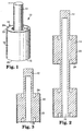
- Figure 1 is a perspective view of a horn of the present invention with a single weld surface.
- Figure 2 is a cross-sectional view of a horn of another embodiment of the present invention with multiple weld surfaces.
- Figure 3 is a cross-sectional view of a horn of another embodiment of the present invention.
- the rotary horn of this invention can be a full wavelength acoustic rotary horn, a half wavelength horn, or a horn of a multiple of half wavelengths.
- the horn can be an ultiasonic horn.
- the horn imparts energy at a selected wavelength, frequency, and amplitude.
- the horn can ultrasonically weld parts over a relatively long width with a desired (often constant) amplitude at the radial weld face.
- the rotary horn can maintain a controlled amplitude across the weld face width by placing an undercut between the inner cylinder and the radial weld face.
- the rotary horn 10, shown in Figure 1 includes a cylindrical shaft 12 having an axial input end 11 and an axial output end 13.
- a cylindrical welding portion 14 is mounted on at coaxial with the shaft 12.
- the shaft 12 can have a hollow portion 15. This hollow portion 15 can extend for more than half of the axial length of the shaft: 12 and can be longer than the welding portion 14. Also, the shaft can extend for more than half of the axial length of the welding portion.
- the diameter of the welding portion 14 can be greater than that of the shaft 12. As shown, the welding portion 14 has a radially outer cylindrical weld face 16 having a diameter that expands and contracts with the application of ultrasonic energy. First and second opposing end portions 18, 20 are formed on the ends of the welding portion 14.
- the center of the weld face 16 should be placed at the point of maximum deflection in the radial direction of the shaft 12. This is a nodal point for the axial motion of the horn 10. If the center of the weld face 16 is shifted above the maximum deflection point, the amplitude at the bottom is higher than the top. If the weld face 16 is placed below the maximum deflection point, the amplitude at the top is higher.
- the gain can be changed at the weld face 16 by changing the mass at the input section of the horn.
- the horns can be extended by any multiple of one-half wavelength.
- the extension can be a separate component mounted on the output end of the horn or it can be formed integrally as one piece with the rest of the horn. This still yields the same amplitude at the weld face at the horn frequency.
- multiple welding portions can be used.
- the attachment of successive welding portions to the shaft 12 can be at a distance (center-to-center distance between adjacent welding portions) of one-half wavelength of the horn material. If desired, intermediate welding portions can be skipped so that the welding portions are positioned at full wavelengths of the horn material. This may be particularly necessary for wide weld face widths.
- the inner shaft and the outer welding portion are shown as concentric cylinders of constant diameter.
- the cylinders could have varying radii or be non-concentric, and the welding portion need not be cylindrical to work with various welding configurations.
- the welding portion could be a non-cylindrical conic section. It could be elliptical in the radial direction or can be spherical.
- the rotary horn of this invention is made out of combination of two or more materials to achieve specific advantages, such as low power usage, an increased weld surface hardness, longer horn durability, and increased flexibility in the horn design, when compared to horns made out of one material. (Low power usage reduces heating of the horn which would cause a drop in the operating frequency. Heat generation changes the process conditions and introduces variability in the process.)
- the rotary horn of the illustrated embodiments has a separate sleeve 22 placed on the welding portion 14 to form the weld surface 16.
- the sleeve 22 can be the same length as the welding portion 14, or it can be longer or shorter.
- more than one sleeve 22 can be shrink fit and they can have different diameters and be formed of different materials.
- Figure 3 shows an embodiment combining these features.
- the rotary horn 10 combines the advantages of several materials.
- the main portion of the horn, called the core 24, can be made out of either titanium or aluminum (which have a lower power draw) while the weld surface sleeve 22 can be made out of hardened steel to improve durability.
- Table 1 compares the text book material properties of aluminum, titanium, and steel.
- Table 2 compares the design and behavior of rotary horns made of the materials compared in Table 1. Because the materials have approximately the same ratio of modulus to density, the shape and geometry of the horn made of each material is similar.
- Titanium is best at high amplitudes because of its higher factor of safety.
- the power drawn and heat generated in the horn is proportional to the strain energy, which is a function of the modulus and the square of strain (square of amplitude).
- the power drawn in titanium and steel horns is 1.6 and 3.0 times more than that of aluminum horns, respectively. If the amplitude is doubled, the power draw is significantly higher in steel compared to aluminum and titanium. Because the thermal conductivity is higher in aluminum, the localized heat generation at the high strain region is better conducted to other parts, allowing the horn to cool quickly and uniformly.
- Tool steel is far harder than aluminum and titanium. Hence there is less surface damage when a steel horn is used against an anvil. Aluminum and titanium are more ductile. This means that the presence of micro cracks are less detrimental than compared to a hardened steel horn.
- Aluminum is cheaper and easier to machine than the other materials. Steel is cheaper and easier to machine before hardening than titanium. Titanium is expensive and costs significantly more to machine.
- the rotary horn 10 combines the advantages of these multiple materials.
- the horn draws low power like an aluminum horn, has a hard weld surface like a steel horn, is easy to machine, and is relatively inexpensive.
- the core made of titanium and the sleeve made of hardened D2 tool steel the horn has good strength and a hard weld surface.
- the weld patterns can be incorporated into the sleeve. If a new pattern is desired, only the sleeve need be changed; the entire horn need not be destroyed. Another advantage is that if the horn frequency is higher than desired, a new sleeve with a higher thickness can be fitted, tuning the horn without making an entirely new horn. When the sleeve is shrunk fit over the core, the sleeve is subjected to hoop tensile stress while the core is subjected to compressive stress.
- the sleeve can be shrink fit at other locations. For example, a sleeve can be placed inside the hollow portion 15 so that the sleeve is under compression.
- the current invention permits the cutouts to be made in the core with the sleeve shrunk fit over the cutouts and the core to close the slots. This simplifies manufacturing these types of horns.
- the sleeve 22 can be placed on the core 24 by any method including shrink fitting, internal screws, and adhesive.
- shrink fitting the outer diameter of the core 24 is greater than the inner diameter of the sleeve 22.
- This interference must be carefully designed. If the interference is low, then the shear stress generated during the vibration causes slippage resulting in heat generation at the core-sleeve interface. If the interference is too high, the hoop tensile stress in the sleeve due to shrink fit superimposed with the vibrational stress can cause the sleeve to fail.
- a structural adhesive at the interface of core and sleeve can be used along with shrink fitting. The compressive stress from the shrink fit helps to hold the adhesive.
- a knurling on the interface surfaces can help contain the adhesive. If adhesive is not used, a diameter interference of about 2 mil per inch of horn diameter is desired.
- shrink fitting the core of the horn can be cooled in dry ice and the sleeve is heated in an oven. Because of the shrinkage in the outer diameter of the core, there is no need for excessive heating of the sleeve.
- the horn has been described as being formed of aluminum, titanium, and steel, other materials, metals and nonmetals, can be used. Also, the horn can be made with more than two materials. A sleeve of harder material can also be placed on other portions of the horn where reduced wear is desired, such as the nodal region to reduce wear because of bearing mounting.
Abstract
Description
- The present invention relates to a rotary acoustic horn according to the pre-characterising part of claim 1 and of claim 5 respectively.
- In acoustic welding, such as ultrasonic welding, two parts to be joined (typically thermoplastic parts) are placed directly below an ultrasonic horn. In plunge welding, the horn plunges (travels toward the parts) and transmits vibrations into the adjacent part. The vibrations travel through this part to the interface of the two parts. Here, the vibrational energy is converted to heat due to intermolecular friction that melts and fuses the two parts. When the vibrations stop, the two parts solidify under force, producing a weld at the joining surface.
- Continuous ultrasonic welding is typically used for sealing fabrics, films, and other parts. In this mode, typically the ultrasonic horn is stationary and the part is moved beneath it. Scan welding is a type of continuous welding in which the part is scanned beneath one or more stationary horns. In transverse welding, both the table over which the parts pass and the part being welded remain stationary with respect to each other while moving underneath the horn or while the horn moves over them.
- Many uses of ultrasonic energy for bonding and cutting thermoplastic materials involve ultrasonic horns or tools. A horn is an acoustical tool usually having a length of a multiple of one-half of the horn material wavelength and made of, for example, aluminum, titanium, or steel that transfers the mechanical vibratory energy to the part. (Typically, these materials have wavelengths of approximately 25 cm (10 in).) Horn displacement or amplitude is the peak-to-peak movement of the horn face. The ratio of horn output amplitude to the horn input amplitude is termed gain. Gain is a function of the ratio of the mass of the horn at the vibration input and output sections. Generally, in horns, the direction of amplitude at the face of the horn is coincident with the direction of the applied mechanical vibrations.
- Traditionally, ultrasonic cutting and welding use horns which vibrate axially against a rigid anvil, with the material to be welded or cut being placed between the horn and anvil. Alternatively, in continuous high speed welding or cutting, the horn is stationary while the anvil is rotated, and the part passes between the horn and the anvil. In these cases, the linear velocity of the part is matched with the tangential velocity of the working surface of the rotating anvil.
- There are, however, some limitations to this system. Because the part to be welded is continuously passed between the narrow gap formed by the anvil and the horn, compression variations are created due to part thickness nonuniformities. Drag exists between the part and the horn and may cause residual stresses in the welded region. These factors affect the weld quality and strength which, in turn, limit the line speeds. Also, the gap between the rotating anvil and the horn limits the compressible bulk or thickness of the parts to be bonded.
- One way to minimize these limitations is to shape the working surface of the horn to attain a progressive convergent or divergent gap depending upon the part. This does not completely solve the problem of moving the material to be bonded past a stationary horn, as an intimate contact is needed for efficient acoustic energy transfer.
- The best way to attain high quality and high speed ultrasonic welds is to use a rotary horn with a rotating anvil. Typically, a rotary horn is cylindrical and rotates around an axis. The input vibration is in the axial direction and the output vibration is in the radial direction. The horn and anvil are two cylinders close to each other, rotating in opposite directions with equal tangential velocities. The parts to be bonded pass between these cylindrical surfaces at a linear velocity equal to the tangential velocity of these cylindrical surfaces. Matching the tangential velocities of the horn and the anvil with the linear velocity of the material minimizes the drag between the horn and the material. The excitation in the axial direction is similar to that in conventional plunge welding.
- US-A-5 096 532 describes two classes of rotary horn. The patent compares a commercially available rotary horn, manufactured by Mecasonic-KLN, Inc. of Fullerton, California (Mecasonic horn) and a rotary horn described in US-A-5 096 532. The shape of the horn of US-A-5 096 532 differs from that of the Mecasonic horn; the horn of US-A 5 096 532 is solid, and the Mecasonic horn is a partially hollowed cylinder.
- The Mecasonic horn is a full wavelength horn. The axial vibration excites the cylindrical bending mode to provide the radial motion, and the mode of vibration depends on Poisson's ratio. The radial motion of the weld face is in phase with the excitation, and there are two nodes for the axial motion, and two nodes for radial motion. The horn of US-A-5 096 532 is a half wavelength horn. The axial vibration provides the radial motion. The mode of vibration is independent of Poisson's ratio. The radial motion of the weld face is out of phase with the excitation, and there is only one node, at the geometric center of the weld face.
- US-A- 5 707 483 and US-A-5 645 681 describe novel rotary acoustic horns.
- In some cases, a carbide tip is brazed to the welding surface of a titanium or aluminum bar (nonrotating) horn to improve the wear characteristics. Also, a thin coating of hard material is placed on the weld surface to improve wear. The node is a position on the horn where the axial vibration is a minimum or zero. In an "Elmore" type booster, the nodal mount (on which clamping occurs) is attached to the booster by either a set screw or a shrink fit.
- However, there is no suggestion anywhere of making rotary horns of multiple materials. Known rotary horns all have the same material on the welding surface as on the remainder of the welding portion. These horns are made out of aluminum (7075-T6), titanium (6al-4v) or steel (D2 tool steel, stainless steel, 15-5 PH, or other steels). Each of these materials has advantages and disadvantages. Generally the hardness of aluminum and titanium is low when compared to the hardness of the anvil. Therefore the weld surface of the horn is relatively easily damaged (such as by gouging) when used against a hard anvil. Damage is more pronounced if the horn directly contacts the anvil such as in a cut and seal operation or when the horn rides on the anvil without material in between.
- To improve durability, rotary horns can be made with harder material such as D2 tool steel or crucible powder metal tool steel. Because the horn material is harder than the anvil, the horn welding surface is not scratched or gouged. However operating steel horns requires significantly more power than an aluminum or a titanium horn. More power draw heats the horn at higher amplitudes.
- WO-A-94/14583 relates to a web cutting apparatus and describes such an apparatus employing an ultrasonically-vibrated rotating cylinder comprising an annular piezoelectric core surrounded by a titanium alloy sleeve which acts as a booster for the ultrasonic vibrations. The cylinder oscillates in a circumferential oscillation mode. The piezoelectric crystals act as a converter to translate electrical energy to mechanical energy.
- US-A-5 820 011 relates to an ultrasonic tool horn for use in ultrasonic machining, welding, etc., that has a horn main body made of heat-treatable aluminum alloy. The aluminum alloy is heat-treated so as to be as hard as 100 or more on the Vickers hardness scale. A thin intermediate layer of a non-heat-treatable aluminum alloy may be provided between the horn main body and a ceramic tool attached to a slender end portion of the horn main body.
- US-A-3 224 915 relates to a method of joining thermoplastic sheet material by ultrasonic vibrations. The sealing tool of the device of US-A-3 224 915 is constituted by a metal rim or ring forming the periphery of a rotary vibrator, and radially directed mechanical vibrations are generated within the rotary vibrator and transmitted to the peripheral ring tool to cause joining together of the thermoplastic sheet material.
- It is an object of the present invention to provide an improved rotary acoustic horn for imparting energy at a selected wavelength, frequency and amplitude.
- This object is achieved according to the invention with the rotary acoustic horn as defined in independent claim 1 and with the rotary acoustic horn as defined in independent claim 5.
- Particular embodiments of the invention are the subject of the respective dependent claims.
- The rotary acoustic horn of the invention imparts energy at a selected wavelength, frequency, and amplitude. The horn includes a shaft having an axial input end and an axial output end. A welding portion is mounted on the shaft. The welding portion has a weld face that expands and contracts with the application of acoustic energy to the input end of the shaft. The horn is formed of at least two materials.
- At least a portion of the weld face can be formed of a different material than the remainder of the welding portion. The welding portion can include a sleeve. The sleeve can be shrink fit onto the welding portion. The length of the sleeve can be less than, equal to, or greater than the length of the weld face.
- The horn can also be formed of a single material, yet the welding portion can be formed of a core portion and a sleeve portion, such that characteristics of the horn can be changed by changing the sleeve portion.
- The invention will now be described in detail in connection with the drawings.
- Figure 1 is a perspective view of a horn of the present invention with a single weld surface.
- Figure 2 is a cross-sectional view of a horn of another embodiment of the present invention with multiple weld surfaces.
- Figure 3 is a cross-sectional view of a horn of another embodiment of the present invention.
- The rotary horn of this invention can be a full wavelength acoustic rotary horn, a half wavelength horn, or a horn of a multiple of half wavelengths. The horn can be an ultiasonic horn. The horn imparts energy at a selected wavelength, frequency, and amplitude. The horn can ultrasonically weld parts over a relatively long width with a desired (often constant) amplitude at the radial weld face. The rotary horn can maintain a controlled amplitude across the weld face width by placing an undercut between the inner cylinder and the radial weld face.
- The
rotary horn 10, shown in Figure 1, includes acylindrical shaft 12 having anaxial input end 11 and anaxial output end 13. Acylindrical welding portion 14 is mounted on at coaxial with theshaft 12. Theshaft 12 can have ahollow portion 15. Thishollow portion 15 can extend for more than half of the axial length of the shaft: 12 and can be longer than thewelding portion 14. Also, the shaft can extend for more than half of the axial length of the welding portion. - The diameter of the
welding portion 14 can be greater than that of theshaft 12. As shown, thewelding portion 14 has a radially outer cylindrical weld face 16 having a diameter that expands and contracts with the application of ultrasonic energy. First and secondopposing end portions welding portion 14. - The center of the weld face 16 should be placed at the point of maximum deflection in the radial direction of the
shaft 12. This is a nodal point for the axial motion of thehorn 10. If the center of the weld face 16 is shifted above the maximum deflection point, the amplitude at the bottom is higher than the top. If the weld face 16 is placed below the maximum deflection point, the amplitude at the top is higher. - The gain can be changed at the weld face 16 by changing the mass at the input section of the horn. The horns can be extended by any multiple of one-half wavelength. The extension can be a separate component mounted on the output end of the horn or it can be formed integrally as one piece with the rest of the horn. This still yields the same amplitude at the weld face at the horn frequency.
- As shown in Figure 2, multiple welding portions can be used. The attachment of successive welding portions to the
shaft 12 can be at a distance (center-to-center distance between adjacent welding portions) of one-half wavelength of the horn material. If desired, intermediate welding portions can be skipped so that the welding portions are positioned at full wavelengths of the horn material. This may be particularly necessary for wide weld face widths. - The inner shaft and the outer welding portion are shown as concentric cylinders of constant diameter. However, the cylinders could have varying radii or be non-concentric, and the welding portion need not be cylindrical to work with various welding configurations. For example, the welding portion could be a non-cylindrical conic section. It could be elliptical in the radial direction or can be spherical.
- The rotary horn of this invention is made out of combination of two or more materials to achieve specific advantages, such as low power usage, an increased weld surface hardness, longer horn durability, and increased flexibility in the horn design, when compared to horns made out of one material. (Low power usage reduces heating of the horn which would cause a drop in the operating frequency. Heat generation changes the process conditions and introduces variability in the process.)
- The rotary horn of the illustrated embodiments has a
separate sleeve 22 placed on thewelding portion 14 to form theweld surface 16. Thesleeve 22 can be the same length as thewelding portion 14, or it can be longer or shorter. On the same welding portion, more than onesleeve 22 can be shrink fit and they can have different diameters and be formed of different materials. Figure 3 shows an embodiment combining these features. - The
rotary horn 10 combines the advantages of several materials. For example, the main portion of the horn, called thecore 24, can be made out of either titanium or aluminum (which have a lower power draw) while theweld surface sleeve 22 can be made out of hardened steel to improve durability. - Table 1 compares the text book material properties of aluminum, titanium, and steel. Table 2 compares the design and behavior of rotary horns made of the materials compared in Table 1. Because the materials have approximately the same ratio of modulus to density, the shape and geometry of the horn made of each material is similar.
Material Properties Material Aluminum Titanium Steel (Hardened) Modulus of Elasticity, E, (MPa) 6.88 x 10⁴ 11.0 x 10⁴ 20.6 x 10⁴ Density, ρ, (kg/m3) 2796 4429 8028 Fatigue strength, σe, (MPa) 165-234 517-634 621-758 Hardness, Rockwell C Less than 20 36-40 56-60 Ductility (% strain in 5.08 cm sample) 12 8-10 4-5 Thermal Conductivity Watt/m-°K 121 7 35-43 Design and behavior of the horn Material Aluminum Titanium Steel
(Hardened)Shape and Geometry f(E/p) Similar to others Similar to others Similar to others Amplitude, A 1.0 1.0 1.0 Stress, σ = f(E x A) 1.0 1.6 3.0 Factor of safety (Approximately)=(σe/σ) 1.2 2.0 1.3 Power =
f(E x A2)A=1.0 1.0 1.6 3.0 A=2.0 4.0 6.4 12.0 - Titanium is best at high amplitudes because of its higher factor of safety. The power drawn and heat generated in the horn is proportional to the strain energy, which is a function of the modulus and the square of strain (square of amplitude). Thus, the power drawn in titanium and steel horns is 1.6 and 3.0 times more than that of aluminum horns, respectively. If the amplitude is doubled, the power draw is significantly higher in steel compared to aluminum and titanium. Because the thermal conductivity is higher in aluminum, the localized heat generation at the high strain region is better conducted to other parts, allowing the horn to cool quickly and uniformly.
- Tool steel is far harder than aluminum and titanium. Hence there is less surface damage when a steel horn is used against an anvil. Aluminum and titanium are more ductile. This means that the presence of micro cracks are less detrimental than compared to a hardened steel horn.
- Aluminum is cheaper and easier to machine than the other materials. Steel is cheaper and easier to machine before hardening than titanium. Titanium is expensive and costs significantly more to machine.
- The
rotary horn 10 combines the advantages of these multiple materials. With the core 24 made of aluminum and thesleeve 22 made of hardened D2 tool steel, for example, the horn draws low power like an aluminum horn, has a hard weld surface like a steel horn, is easy to machine, and is relatively inexpensive. With the core made of titanium and the sleeve made of hardened D2 tool steel, the horn has good strength and a hard weld surface. - There are other advantages of using a separate sleeve as the weld surface. The weld patterns can be incorporated into the sleeve. If a new pattern is desired, only the sleeve need be changed; the entire horn need not be destroyed. Another advantage is that if the horn frequency is higher than desired, a new sleeve with a higher thickness can be fitted, tuning the horn without making an entirely new horn. When the sleeve is shrunk fit over the core, the sleeve is subjected to hoop tensile stress while the core is subjected to compressive stress. Since aluminum fatigue strength is low (stress reversal is due to vibration) a pre-compression by shrink fit can increase the life of the horn. If the sleeve is intended to apply pre-compression, the sleeve can be shrink fit at other locations. For example, a sleeve can be placed inside the
hollow portion 15 so that the sleeve is under compression. - If internal cutouts or slots are to be made in the welding portion, for example to achieve uniform amplitude, the current invention permits the cutouts to be made in the core with the sleeve shrunk fit over the cutouts and the core to close the slots. This simplifies manufacturing these types of horns.
- The
sleeve 22 can be placed on thecore 24 by any method including shrink fitting, internal screws, and adhesive. In shrink fitting, the outer diameter of thecore 24 is greater than the inner diameter of thesleeve 22. This interference must be carefully designed. If the interference is low, then the shear stress generated during the vibration causes slippage resulting in heat generation at the core-sleeve interface. If the interference is too high, the hoop tensile stress in the sleeve due to shrink fit superimposed with the vibrational stress can cause the sleeve to fail. A structural adhesive at the interface of core and sleeve can be used along with shrink fitting. The compressive stress from the shrink fit helps to hold the adhesive. Also, a knurling on the interface surfaces can help contain the adhesive. If adhesive is not used, a diameter interference of about 2 mil per inch of horn diameter is desired. In shrink fitting, the core of the horn can be cooled in dry ice and the sleeve is heated in an oven. Because of the shrinkage in the outer diameter of the core, there is no need for excessive heating of the sleeve. - Various changes and modifications can be made in the invention without departing from the scope of the appended claims. Although the horn has been described as being formed of aluminum, titanium, and steel, other materials, metals and nonmetals, can be used. Also, the horn can be made with more than two materials. A sleeve of harder material can also be placed on other portions of the horn where reduced wear is desired, such as the nodal region to reduce wear because of bearing mounting.
Claims (7)
- A rotary acoustic horn (10) for imparting energy at a selected wavelength, frequency, and amplitude, wherein the horn comprises:wherein the horn is formed of at least first and second materials.a shaft (12) having an axial input end (11) and an axial output end (13); characterized byat least one welding portion (14) mounted on the shaft (12), wherein the welding portion comprises a weld face (16) that expands and contracts with the application of acoustic energy to the input end of the shaft, and
- The rotary acoustic horn (10) of claim 1 wherein at least a portion of the weld face (16) is formed of the second material and the remainder of the welding portion is formed of the first material.
- The rotary acoustic horn (10) of claim 2 wherein the portion of the weld face (16) that is formed of the second material comprises at least one sleeve (22).
- The rotary acoustic horn (10) of claim 3 wherein the length of the sleeve (22) is one of less than, equal to, or greater than the length of the weld face (16).
- A rotary acoustic horn (10) for imparting energy at a selected wavelength, frequency, and amplitude, wherein the horn comprises a shaft (12) having an axial input end (11) and an axial output end (13); characterized by a welding portion (14) mounted on the shaft, wherein the welding portion comprises a weld face (16) that expands and contracts with the application of acoustic energy to the input end of the shaft; and wherein the welding portion is formed of a core portion (24) and a sleeve portion (22), such that characteristics of the horn can be changed by changing the sleeve portion.
- The rotary acoustic horn (10) of claim 5 wherein the core portion (24) is formed of a first material and the sleeve portion (22) is formed of a second material.
- The rotary acoustic horn (10) of any of claims 3 or 6 wherein the first material includes at least one of aluminum and titanium and the second material includes steel.
Applications Claiming Priority (3)
| Application Number | Priority Date | Filing Date | Title |
|---|---|---|---|
| US157033 | 1998-09-18 | ||
| US09/157,033 US6059923A (en) | 1998-09-18 | 1998-09-18 | Rotary acoustic horn with sleeve |
| PCT/US1999/000681 WO2000016966A1 (en) | 1998-09-18 | 1999-01-12 | Rotary acoustic horn with sleeve |
Publications (2)
| Publication Number | Publication Date |
|---|---|
| EP1113916A1 EP1113916A1 (en) | 2001-07-11 |
| EP1113916B1 true EP1113916B1 (en) | 2003-05-02 |
Family
ID=22562099
Family Applications (1)
| Application Number | Title | Priority Date | Filing Date |
|---|---|---|---|
| EP19990905431 Expired - Lifetime EP1113916B1 (en) | 1998-09-18 | 1999-01-12 | Rotary acoustic horn with sleeve |
Country Status (9)
| Country | Link |
|---|---|
| US (1) | US6059923A (en) |
| EP (1) | EP1113916B1 (en) |
| JP (1) | JP4050469B2 (en) |
| KR (1) | KR100541197B1 (en) |
| AU (1) | AU2558799A (en) |
| BR (1) | BR9913753A (en) |
| CA (1) | CA2343141A1 (en) |
| DE (1) | DE69907484T2 (en) |
| WO (1) | WO2000016966A1 (en) |
Cited By (2)
| Publication number | Priority date | Publication date | Assignee | Title |
|---|---|---|---|---|
| DE10343325A1 (en) * | 2003-08-13 | 2005-03-10 | Herrmann Ultraschalltechnik | Apparatus for continuous bonding and / or solidification of material webs by means of ultrasound |
| EP1514670A2 (en) | 2003-08-13 | 2005-03-16 | Herrmann Ultraschalltechnik GmbH & Co. KG | Apparatus for continuously bonding and/or consolidating of web material by ultrasonics |
Families Citing this family (24)
| Publication number | Priority date | Publication date | Assignee | Title |
|---|---|---|---|---|
| US6123792A (en) * | 1998-08-14 | 2000-09-26 | Kimberly-Clark Worldwide, Inc. | Methods and apparatus for intermittent rotary ultrasonic bonding system |
| US6217686B1 (en) * | 1999-06-28 | 2001-04-17 | Virtual Ink Corp. | Ultrasound welding apparatus |
| FR2809984B1 (en) * | 2000-06-09 | 2006-07-14 | Aplix Sa | ROTARY SELOTRODE FOR CONTINUOUS WELDING ON LARGE WIDTH |
| US6877975B2 (en) * | 2000-10-17 | 2005-04-12 | David G. Wuchinich | Rolling pin horn |
| US6457626B1 (en) * | 2001-01-29 | 2002-10-01 | Branson Ultrasonics Corporation | Symmetric ultrasonic rotary horn |
| US6676003B2 (en) * | 2001-12-18 | 2004-01-13 | Kimberly-Clark Worldwide, Inc. | Rigid isolation of rotary ultrasonic horn |
| US6786383B2 (en) * | 2002-11-14 | 2004-09-07 | Kimberly-Clark Worldwide, Inc. | Ultrasonic horn assembly with fused stack components |
| US6767420B2 (en) * | 2002-12-20 | 2004-07-27 | Kimberly-Clark Worldwide, Inc. | Ultrasonic horn with isotropic breathing characteristics |
| US6766937B2 (en) * | 2002-12-20 | 2004-07-27 | Kimberly-Clark Worldwide, Inc. | Ultrasonic rotary horn repair |
| US6758925B1 (en) | 2002-12-20 | 2004-07-06 | Kimberly-Clark Worldwide, Inc. | Acoustical energy transfer component |
| US20040164135A1 (en) * | 2003-02-22 | 2004-08-26 | Lie-Zhong Gong | Packaging system |
| US20040164134A1 (en) * | 2003-02-22 | 2004-08-26 | Lie-Zhong Gong | Packaging system |
| US6786384B1 (en) * | 2003-06-13 | 2004-09-07 | 3M Innovative Properties Company | Ultrasonic horn mount |
| US7062972B2 (en) * | 2003-07-21 | 2006-06-20 | Horiba Instruments, Inc. | Acoustic transducer |
| US7021145B2 (en) * | 2003-07-21 | 2006-04-04 | Horiba Instruments, Inc | Acoustic transducer |
| JP4502325B2 (en) * | 2005-02-28 | 2010-07-14 | 財団法人電力中央研究所 | Ultrasonic horn |
| WO2006099872A1 (en) * | 2005-03-23 | 2006-09-28 | 3L-Ludvigsen A/S | Rotary ultrasonic sealer |
| EP1837161A1 (en) * | 2006-03-24 | 2007-09-26 | Nippon Consultants B.V. | Sealing Device |
| WO2007065951A1 (en) * | 2005-12-08 | 2007-06-14 | Nippon Consultants B.V. | Sealing device |
| US7837082B2 (en) * | 2006-05-23 | 2010-11-23 | Federal-Mogul World Wide, Inc. | Powder metal friciton stir welding tool and method of manufacture thereof |
| US8196797B2 (en) | 2006-05-23 | 2012-06-12 | Federal-Mogul Corporation | Powder metal ultrasonic welding tool and method of manufacture thereof |
| WO2008037256A2 (en) * | 2006-09-28 | 2008-04-03 | 3L-Ludvigsen A/S | Rotary ultrasonic sealer |
| EP2762842B1 (en) * | 2013-01-28 | 2024-02-14 | Krohne AG | Ultrasonic transducer for an ultrasonic flow rate meter |
| JP7423847B1 (en) | 2023-07-20 | 2024-01-29 | 祐記 斉藤 | composite metal rotary horn |
Family Cites Families (17)
| Publication number | Priority date | Publication date | Assignee | Title |
|---|---|---|---|---|
| US3224915A (en) * | 1962-08-13 | 1965-12-21 | Cavitron Ultrasonics Inc | Method of joining thermoplastic sheet material by ultrasonic vibrations |
| FR2082090A5 (en) * | 1970-03-03 | 1971-12-10 | Scotto Jean Pierre | Ultrasonic welding tool - shaped to convert an axial impulse to a rolling radial contact at an enlarged waist |
| DE3229076A1 (en) * | 1981-08-07 | 1983-03-24 | Pola Chemical Industries, Inc., Shizuoka | METHOD AND DEVICE FOR WELDING THE BOTTOM OF A TUBULAR RESIN CONTAINER |
| US4534818A (en) * | 1983-12-22 | 1985-08-13 | Frito-Lay, Inc. | Method and apparatus for ultrasonic sealing |
| US4668316A (en) * | 1985-12-10 | 1987-05-26 | Branson Ultrasonics Corporation | Welding thin thermoplastic film by ultrasonic energy |
| US5096532A (en) * | 1990-01-10 | 1992-03-17 | Kimberly-Clark Corporation | Ultrasonic rotary horn |
| US5057182A (en) * | 1990-01-19 | 1991-10-15 | Sonokinetics Group | Ultrasonic comb horn and methods for using same |
| US5087320A (en) * | 1990-05-18 | 1992-02-11 | Kimberly-Clark Corporation | Ultrasonic rotary horn having improved end configuration |
| US5110403A (en) * | 1990-05-18 | 1992-05-05 | Kimberly-Clark Corporation | High efficiency ultrasonic rotary horn |
| GB9226932D0 (en) * | 1992-12-24 | 1993-02-17 | Molins Plc | Web cutting device |
| GB2282559B (en) * | 1993-10-07 | 1998-04-15 | Rawson Francis F H | Ultrasonic cutting device |
| US5552013A (en) * | 1994-06-29 | 1996-09-03 | Kimberly-Clark Corporation | Apparatus and method for rotary bonding |
| JPH091065A (en) * | 1995-04-19 | 1997-01-07 | Ngk Spark Plug Co Ltd | Ultrasonic horn |
| US5645681B1 (en) * | 1996-07-05 | 2000-03-14 | Minnesota Mining & Mfg | Stacked rotary acoustic horn |
| US5707483A (en) * | 1996-07-05 | 1998-01-13 | Minnesota Mining And Manufacturing Company | Rotary acoustic horn |
| US5922170A (en) * | 1997-10-02 | 1999-07-13 | Minnesota Mining And Manufacturing Company | Hollow vibrational horn |
| US5945642A (en) * | 1998-03-13 | 1999-08-31 | Minnesota Mining And Manufacturing Company | Acoustic horn |
-
1998
- 1998-09-18 US US09/157,033 patent/US6059923A/en not_active Expired - Lifetime
-
1999
- 1999-01-12 KR KR1020017003398A patent/KR100541197B1/en not_active IP Right Cessation
- 1999-01-12 DE DE1999607484 patent/DE69907484T2/en not_active Expired - Lifetime
- 1999-01-12 BR BR9913753A patent/BR9913753A/en not_active IP Right Cessation
- 1999-01-12 AU AU25587/99A patent/AU2558799A/en not_active Abandoned
- 1999-01-12 EP EP19990905431 patent/EP1113916B1/en not_active Expired - Lifetime
- 1999-01-12 JP JP2000573903A patent/JP4050469B2/en not_active Expired - Fee Related
- 1999-01-12 CA CA 2343141 patent/CA2343141A1/en not_active Abandoned
- 1999-01-12 WO PCT/US1999/000681 patent/WO2000016966A1/en active IP Right Grant
Cited By (2)
| Publication number | Priority date | Publication date | Assignee | Title |
|---|---|---|---|---|
| DE10343325A1 (en) * | 2003-08-13 | 2005-03-10 | Herrmann Ultraschalltechnik | Apparatus for continuous bonding and / or solidification of material webs by means of ultrasound |
| EP1514670A2 (en) | 2003-08-13 | 2005-03-16 | Herrmann Ultraschalltechnik GmbH & Co. KG | Apparatus for continuously bonding and/or consolidating of web material by ultrasonics |
Also Published As
| Publication number | Publication date |
|---|---|
| CA2343141A1 (en) | 2000-03-30 |
| EP1113916A1 (en) | 2001-07-11 |
| AU2558799A (en) | 2000-04-10 |
| JP4050469B2 (en) | 2008-02-20 |
| DE69907484T2 (en) | 2004-03-11 |
| WO2000016966A1 (en) | 2000-03-30 |
| KR100541197B1 (en) | 2006-01-10 |
| US6059923A (en) | 2000-05-09 |
| KR20010075145A (en) | 2001-08-09 |
| BR9913753A (en) | 2001-06-12 |
| DE69907484D1 (en) | 2003-06-05 |
| JP2002526250A (en) | 2002-08-20 |
Similar Documents
| Publication | Publication Date | Title |
|---|---|---|
| EP1113916B1 (en) | Rotary acoustic horn with sleeve | |
| EP0909225B1 (en) | Rotary acoustic horn | |
| EP0909224B1 (en) | Stacked rotary acoustic horn | |
| EP1077786B1 (en) | Non-nodal mounting system for ultrasonic apparatus | |
| US6547904B1 (en) | Method and apparatus for welding polymer fabrics | |
| US6457626B1 (en) | Symmetric ultrasonic rotary horn | |
| US7754141B2 (en) | Bi-material ultrasonic horn with integral isolation member | |
| EP2300217B1 (en) | Resonant nodal mount for linear ultrasonic horns | |
| US20230038455A1 (en) | Rotary Acoustic Horn | |
| MXPA01002815A (en) | Rotary acoustic horn with sleeve |
Legal Events
| Date | Code | Title | Description |
|---|---|---|---|
| PUAI | Public reference made under article 153(3) epc to a published international application that has entered the european phase |
Free format text: ORIGINAL CODE: 0009012 |
|
| 17P | Request for examination filed |
Effective date: 20010404 |
|
| AK | Designated contracting states |
Kind code of ref document: A1 Designated state(s): CH DE FR GB IT LI NL |
|
| 17Q | First examination report despatched |
Effective date: 20010723 |
|
| GRAG | Despatch of communication of intention to grant |
Free format text: ORIGINAL CODE: EPIDOS AGRA |
|
| GRAG | Despatch of communication of intention to grant |
Free format text: ORIGINAL CODE: EPIDOS AGRA |
|
| GRAG | Despatch of communication of intention to grant |
Free format text: ORIGINAL CODE: EPIDOS AGRA |
|
| GRAH | Despatch of communication of intention to grant a patent |
Free format text: ORIGINAL CODE: EPIDOS IGRA |
|
| GRAH | Despatch of communication of intention to grant a patent |
Free format text: ORIGINAL CODE: EPIDOS IGRA |
|
| GRAA | (expected) grant |
Free format text: ORIGINAL CODE: 0009210 |
|
| AK | Designated contracting states |
Designated state(s): CH DE FR GB IT LI NL |
|
| REG | Reference to a national code |
Ref country code: GB Ref legal event code: FG4D |
|
| REG | Reference to a national code |
Ref country code: CH Ref legal event code: EP |
|
| REF | Corresponds to: |
Ref document number: 69907484 Country of ref document: DE Date of ref document: 20030605 Kind code of ref document: P |
|
| ET | Fr: translation filed | ||
| PLBE | No opposition filed within time limit |
Free format text: ORIGINAL CODE: 0009261 |
|
| STAA | Information on the status of an ep patent application or granted ep patent |
Free format text: STATUS: NO OPPOSITION FILED WITHIN TIME LIMIT |
|
| 26N | No opposition filed |
Effective date: 20040203 |
|
| PGFP | Annual fee paid to national office [announced via postgrant information from national office to epo] |
Ref country code: NL Payment date: 20051216 Year of fee payment: 8 |
|
| NLV4 | Nl: lapsed or anulled due to non-payment of the annual fee |
Effective date: 20070801 |
|
| REG | Reference to a national code |
Ref country code: CH Ref legal event code: PFA Owner name: MINNESOTA MINING AND MANUFACTURING COMPANY Free format text: MINNESOTA MINING AND MANUFACTURING COMPANY#3M CENTER, P.O. BOX 33427#ST. PAUL, MINNESOTA 55133-3427 (US) -TRANSFER TO- MINNESOTA MINING AND MANUFACTURING COMPANY#3M CENTER, P.O. BOX 33427#ST. PAUL, MINNESOTA 55133-3427 (US) |
|
| PG25 | Lapsed in a contracting state [announced via postgrant information from national office to epo] |
Ref country code: NL Free format text: LAPSE BECAUSE OF NON-PAYMENT OF DUE FEES Effective date: 20070801 |
|
| PGFP | Annual fee paid to national office [announced via postgrant information from national office to epo] |
Ref country code: CH Payment date: 20090126 Year of fee payment: 11 |
|
| PGFP | Annual fee paid to national office [announced via postgrant information from national office to epo] |
Ref country code: IT Payment date: 20090128 Year of fee payment: 11 |
|
| REG | Reference to a national code |
Ref country code: CH Ref legal event code: PL |
|
| PG25 | Lapsed in a contracting state [announced via postgrant information from national office to epo] |
Ref country code: LI Free format text: LAPSE BECAUSE OF NON-PAYMENT OF DUE FEES Effective date: 20100131 Ref country code: CH Free format text: LAPSE BECAUSE OF NON-PAYMENT OF DUE FEES Effective date: 20100131 |
|
| PG25 | Lapsed in a contracting state [announced via postgrant information from national office to epo] |
Ref country code: IT Free format text: LAPSE BECAUSE OF NON-PAYMENT OF DUE FEES Effective date: 20100112 |
|
| PGFP | Annual fee paid to national office [announced via postgrant information from national office to epo] |
Ref country code: FR Payment date: 20110128 Year of fee payment: 13 |
|
| REG | Reference to a national code |
Ref country code: FR Ref legal event code: ST Effective date: 20120928 |
|
| PG25 | Lapsed in a contracting state [announced via postgrant information from national office to epo] |
Ref country code: FR Free format text: LAPSE BECAUSE OF NON-PAYMENT OF DUE FEES Effective date: 20120131 |
|
| PGFP | Annual fee paid to national office [announced via postgrant information from national office to epo] |
Ref country code: DE Payment date: 20180103 Year of fee payment: 20 Ref country code: GB Payment date: 20180110 Year of fee payment: 20 |
|
| REG | Reference to a national code |
Ref country code: DE Ref legal event code: R071 Ref document number: 69907484 Country of ref document: DE |
|
| REG | Reference to a national code |
Ref country code: GB Ref legal event code: PE20 Expiry date: 20190111 |
|
| PG25 | Lapsed in a contracting state [announced via postgrant information from national office to epo] |
Ref country code: GB Free format text: LAPSE BECAUSE OF EXPIRATION OF PROTECTION Effective date: 20190111 |