EP1077313B1 - Vorrichtung zur Regelung eines elektromagnetisch angetriebenen Brennkraftmaschinenventils - Google Patents
Vorrichtung zur Regelung eines elektromagnetisch angetriebenen Brennkraftmaschinenventils Download PDFInfo
- Publication number
- EP1077313B1 EP1077313B1 EP00116786A EP00116786A EP1077313B1 EP 1077313 B1 EP1077313 B1 EP 1077313B1 EP 00116786 A EP00116786 A EP 00116786A EP 00116786 A EP00116786 A EP 00116786A EP 1077313 B1 EP1077313 B1 EP 1077313B1
- Authority
- EP
- European Patent Office
- Prior art keywords
- valve
- engine
- lift
- operating mode
- current value
- Prior art date
- Legal status (The legal status is an assumption and is not a legal conclusion. Google has not performed a legal analysis and makes no representation as to the accuracy of the status listed.)
- Expired - Lifetime
Links
Images


Classifications
-
- F—MECHANICAL ENGINEERING; LIGHTING; HEATING; WEAPONS; BLASTING
- F01—MACHINES OR ENGINES IN GENERAL; ENGINE PLANTS IN GENERAL; STEAM ENGINES
- F01L—CYCLICALLY OPERATING VALVES FOR MACHINES OR ENGINES
- F01L9/00—Valve-gear or valve arrangements actuated non-mechanically
- F01L9/20—Valve-gear or valve arrangements actuated non-mechanically by electric means
-
- F—MECHANICAL ENGINEERING; LIGHTING; HEATING; WEAPONS; BLASTING
- F01—MACHINES OR ENGINES IN GENERAL; ENGINE PLANTS IN GENERAL; STEAM ENGINES
- F01L—CYCLICALLY OPERATING VALVES FOR MACHINES OR ENGINES
- F01L2201/00—Electronic control systems; Apparatus or methods therefor
Definitions
- the present invention relates to an apparatus for controlling electromagnetically powered engine valves according to the preamble of independent claim 1 and to a method for controlling electromagnetically powered engine valves according to the preamble of independent claim 12.
- Such an apparatus as well as such a method can be taken from prior art document US 5,743,221.
- opening and closing of an engine valve (an intake-port valve or an exhaust-port valve) of an internal combustion engine are achieved by way of a typical cam-drive mechanism through which the rotational speed of an engine crankshaft is mechanically reduced.
- a cam-drive mechanism it is difficult to optimally control or manage an engine valve open timing and/or an engine valve closure timing and to provide an optimal valve lift, depending on engine operating conditions.
- electromagnetically powered valve operating devices which are capable of operating intake and exhaust valves electromagnetically by way of an electromagnetic force created by an electromagnetic actuator instead of the use of a cam-drive mechanism. Such electromagnetically powered valve operating devices have been disclosed in Japanese Patent Provisional Publication Nos.
- the electromagnetically powered valve operating device as disclosed in the Japanese Patent Provisional Publication Nos. 7-335437 and 9-195736, includes a disk-shaped armature, often called a "plunger", fixedly connected to the valve stem of an engine valve, a pair of electromagnets provided on opposite sides of the armature, and a pair of return springs biasing the armature toward a neutral position corresponding to a substantially middle position between the two opposing electromagnets. Opening and closing of the engine valve are achieved by attracting the armature alternately by the valve-opening side electromagnet and the valve-closing side electromagnet.
- An intake-valve closure timing (IVC), an intake-valve open timing (IVO), an exhaust-valve open timing (EVO), and an exhaust-valve closure timing (EVC) can be continually changed in response to command signals from an electronic control unit (ECU).
- ECU electronice control unit
- the ECU When initiating powered opening of the engine valve, the ECU functions to move the armature from its end-of-displacement in the valve-closing direction (corresponding to a zero lift position) to its end-of-displacement in the valve-opening direction (corresponding to a maximum lift position), by breaking a holding current flowing through an electromagnetic coil of valve-closing side electromagnet and holding the armature at the end-of-displacement corresponding to the zero lift position and by applying an exciting current, often called a "catching current" to an electromagnetic coil of valve-opening side electromagnet.
- the armature when attracting the armature by the electromagnet to initiate powered opening or closing of the engine valve, the armature would be attracted and moved to its end-of-displacement by application of catching current to the valve-opening side electromagnet or the valve-closing side electromagnet.
- the sliding motion In the presence of high frictional resistance to sliding motion of an engine-valve kinetic system (containing at least a valve stem) owing to a high coefficient of viscosity of engine oil at a very low-temperature engine operating condition, or owing to degraded engine oil, the sliding motion is unstable, and thus the valve open timing or valve closure timing, and the valve open period tend to fluctuate. This results in undesirable fluctuations in engine speed.
- the conventional electromagnetically powered valve operating device also suffers from the drawback that a current value of catching current applied to the electromagnet has to be increased in order to attain a full cycle of motion of the armature from one of the end-of-displacement corresponding to the zero lift position and the end-of-displacement corresponding to the maximum lift position to the other against such high frictional resistance to sliding motion. That is, there is a problem of increased electric power consumption.
- Prior art document EP 0 867 602 A teaches an electromagnetically operated valve control system and a method thereof, wherein said system comprises an actuator for opening and closing an intake valve and an exhaust valve,respectively Said actuator opens and closes the intake valve and the exhaust valve by passing and shutting off current supply from the actuator drive circuit.
- Said actuator comprises a first or upper core and a second or lower core, wherein said first core is provided with a lift sensor for detecting the valve lift.
- An actuator control apparatus is provided for energizing and de-energizing said force of the actuator based on the analogue signal from the lift sensor.
- An apparatus and method for controlling electromagnetically powered engine valves can be taken from prior art document US 5,743,221.
- Said prior art document teaches an electromagnetically powered engine valve, that can be operated under normal operation mode and some kind of free-fly operation mode.
- the electromagnetic actuator Within the normal operation mode, which is used under specific load conditions of the engine, the electromagnetic actuator is controlled such that the valve is held in the respective open or closed position.
- the electromagnetic actuator Under low load conditions, the electromagnetic actuator is controlled such that the valve is held in the closed position only, while the respective armature of the valve does not come into engagement with the opening magnet and thereby freely turns back to the closed position.
- intake air amount supplied to the respective cylinder can be reduced.
- an apparatus for controlling an electromagnetically powered engine valve which is capable of minimizing fluctuations in a valve open timing or closure timing of the engine valve, and fluctuations in a valve open period of the engine valve, that is, fluctuations in engine speed, even in presence of high frictional resistance to sliding motion of an engine-valve kinetic system containing at least a valve stem of the engine valve, owing to a high coefficient of viscosity of engine oil at very low-temperature engine operating conditions, or owing to degraded engine oil.
- an apparatus for controlling an electromagnetically powered engine valve which is capable of realizing an optimal valve open timing or closure timing of the engine valve, and an optimal valve open period without increasing electric power consumption.
- said objective is solved by a method for controlling electromagnetically powered engine valves having the features of independent claim 12.
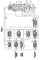
- the electromagnetically powered engine valve control apparatus is exemplified in a four-stroke-cycle internal combustion engine equipped with electromagnetically powered engine valve units (electromagnetically powered intake and exhaust valves).
- Each of the engine valve units includes an engine valve 17 opening and closing an engine-valve port 18, a valve-opening side electromagnet 13, a valve-closing side electromagnet 15, a movable armature or plunger 14 made of magnetic substance and movable between the two opposing electromagnets 13 and 15, a valve-lift sensor 11, an upper return spring (upper coiled valve spring) 12 permanently biasing movable armature 14 (engine valve 17) in a direction closing the engine valve, and a lower coiled valve spring 16 permanently biasing engine valve 17 in a direction opening the engine valve.
- Engine control unit 1 includes a valve-lift detection section 2, a damping-coefficient (C) calculation section 3, a desired engine load calculation section 4, a valve-opening time length (Tcr) determination section 5, an engine speed (N) calculation section 6, a valve open period (To) calculation section 7, an engine temperature (T) determination section 8, a controlled current value determination section 9, and an electromagnet-exciting-current control section 10.
- Valve-lift detection section 2 is provided to monitor or detect a valve lift based on a signal from valve-lift sensor 11.
- Damping-coefficient calculation section 3 is provided to calculate a damping coefficient C (which will be fully described later).
- Desired engine load calculation section 4 (simply, engine load calculation section) is provided to calculate a desired engine load based on an accelerator opening (an amount of depression of the accelerator).
- the accelerator opening is usually sensed by an accelerator opening sensor, such as an accelerator position sensor (not numbered).
- Valve-opening time length determination section 5 is provided to determine a desired valve-opening time length Tcr (simply, a valve-opening time length) substantially corresponding to an angular displacement (expressed in terms of degrees) of an engine crankshaft from a time when the engine valve starts to open to a time when the engine valve reaches its fully opened position) on the basis of both engine speed and desired engine load.
- Engine speed calculation section 6 is provided to calculate engine speed N based on a signal from a crankshaft position sensor or a crank angle sensor (not numbered).
- Valve open period (To) calculation section 7 calculates a desired valve open period (simply, a valve open period) To from a time when the engine valve starts to open to a time when the engine valve closes, on the basis of both the engine speed N and valve-opening time length Tcr.
- Engine temperature determination section 8 is provided to determine engine temperature based on engine coolant temperature sensed by a coolant temperature sensor (a water temperature sensor) or based on lubricating oil temperature sensed by an oil temperature sensor (an engine oil temperature sensor or a transmission oil temperature sensor).
- Controlled current value determination section 9 is provided to determine both a controlled current value of exciting current applied to electromagnet 13 and a controlled current value of exciting current applied to electromagnet 15, on the basis of valve open period To and damping coefficient C.
- Electromagnet-exciting-current control section 10 is provided to drive an electromagnetic coil of electromagnet 13 by application of an exciting current corresponding to the controlled current value for electromagnet 13, and to drive an electromagnetic coil of electromagnet 15 by application of an exciting current corresponding to the controlled current value for electromagnet 15.
- damping coefficient C a valve lift of engine valve 17, obtained during a "free-fly" valve operating mode (which will be fully described later), is denoted by La, and a valve lift of the same engine valve, obtained during a normal valve operating mode (which will be fully described later), is denoted by Lf, a ratio (La/Lf) of valve lift La obtained during the "free-fly valve operating mode" to valve lift Lf obtained during the normal valve operating mode is calculated as damping coefficient C.
- valve-opening time length determination section 5 determines valve-opening time length Tcr based on engine speed and desired engine load
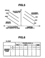
- the valve-opening time length determination section pre-stores a preprogrammed valve-opening time length (Tcr) characteristic map or a preprogrammed Tcr look-up table shown in Fig. 6 showing how a valve-opening time length (Tcr) has to be varied relative to two different parameters, namely engine speed and desired engine load.
- valve-opening time length Tcr is determined by way of map-retrieval based on both engine speed and desired engine load from the preprogrammed Tcr map.
- valve-opening time length indicative values f(x 0 , y 0 ), f(x 1 , y 1 ), ... , f(x n ,y n ) of a certain function f are known for particular engine speed values x 0 , x 1 , ... , x n , and particular engine load values y 0 , y 1 , ... , y n , in the form of map data, accounting for a limited memory capacity of memories incorporated in ECU 1.
- Valve open period calculation section 7 calculates valve open period To based on both engine speed N and valve-opening time length Tcr, from the following expression (1).
- Tcr denotes a valve-opening time length (unit: degrees) substantially corresponding to an angular displacement of engine crankshaft from a time when the engine valve starts to open to a time when the engine valve reaches its fully opened position
- N denotes engine speed (unit: rpm).
- controlled-current value determination section 9 In order for controlled-current value determination section 9 to determine both the controlled current value of exciting current applied to electromagnet 13 and the controlled current value of exciting current applied to electromagnet 15, based on valve open period To and damping coefficient C, controlled current value determination section 9 pre-stores a preprogrammed controlled current value (Ic) characteristic map or a preprogrammed set catching-current value (Ic) look-up table shown in Fig. 7 showing how a controlled current value (a set catching-current value) has to be varied relative to two different parameters, namely a valve open period To and a damping coefficient C.
- Ic controlled current value
- Ic set catching-current value
- controlled current value Ic (catching current value) is determined by way of map-retrieval based on both valve open period To and damping coefficient C from the preprogrammed Ic map.
- the controlled-current-value indicative values f (To 0 , C 0 ), f(To 1 , C 1 ), ... , f(To n , C n ) of a certain function f are known for particular valve open period values To 0 , To 1 , ... , To n , and particular damping coefficient values C 0 , C 1 , ... , C n , in the form of map data, accounting for a limited memory capacity of memories incorporated in ECU 1.
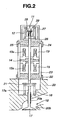
- Fig. 2 there is shown the detailed structure of the electromagnetically powered engine valve unit.
- the electromagnetically powered engine valve unit also includes a valve retainer 21, three-split housings 22, 23, and 24, an axially movable rod 25, a spring seat 26, and a spring cover 27.
- An electromagnetic valve actuator is comprised of at least an axially-movable plunger (consisting of movable armature 14 and rod 25), upper and lower valve springs 12 and 16, upper and lower electromagnetic coils 13a and 15a, and upper and lower electromagnets 13 and 15.
- Movable rod 25 is provided to support movable armature 14 in a manner such that the armature is axially movable between the two opposing electromagnets 13 and 15.
- Valve stem 17a of engine valve 17 is slidably fitted into a cylindrical valve guide 20a tightly fitted into a bore formed in cylinder head 20, so that the valve stem is slidable up and down by way of the valve guide.
- Valve retainer 21 is fixedly connected to the tip of valve stem 17a.
- Valve spring 16 is disposed between valve retainer 21 and cylinder head 20 under preload imposed thereon. For this reason, engine valve 17 is permanently biased in a direction closing engine-valve port 18 of the cylinder head.
- Three-split housings 22,23, and 24 are fixedly mounted on the cylinder head.
- Electromagnets 13 and 15 are accommodated in the internal space defined in the three-split housings (22, 23, 24). Valve-closing side electromagnet 13 is fixedly connected directly to upper housing 24, whereas valve-opening side electromagnet 15 is fixedly connected directly to lower housing 22. Upper electromagnetic coil 13a is disposed in the annular recessed portion formed in upper magnet 13, while lower electromagnetic coil 15a is disposed in the annular recessed portion formed in lower magnet 15. As can be appreciated from an upper-coil power line interconnecting the output port of electromagnet-exciting-current control section 10 and upper coil 13a (see Fig.
- an exciting current (driving current) is applied via a driver circuit of current control section 10 to coil 13a of upper electromagnet 13 so as to attract movable armature 14 toward the lower attracting face of upper magnet 13.
- an exciting current (driving current) is applied via a driver circuit of current control section 10 to coil 15a of lower electromagnet 15 so as to attract movable armature 14 toward the upper attracting face of lower magnet 15.
- Movable rod 25 is coaxially aligned with valve stem 17a and connected to the upper end portion of the valve stem.
- the movable rod is axially slidably fitted into axial central bores of two opposing magnets 13 and 15 and upper and lower housings 24 and 22 integrally connected with the cylindrical housing 23.
- Movable armature 14 is constructed as a disk-shaped member fixed to the middle portion of movable rod 25. More accurately, the movable armature is made of soft magnetic substance.
- Upper spring seat 26 is fixed to the upper end of movable rod 25.
- Upper coiled valve spring 12 is disposed between upper spring seat 26 and an upper wall portion of the spring cover 27, in order to permanently bias movable rod 25 in a direction opening the engine valve.
- valve stem 17a and movable rod 25 are coaxially aligned with each other.
- a kinetic system of engine valve 17 (containing at least movable armature 14, engine valve 17, valve stem 17a, and rod 25), when upper and lower electromagnetic coils 13a and 15a of electromagnets 13 and 15 are de-energized, the kinetic system of engine valve 17 (particularly, the movable armature) is held its neutral position (equilibrium position) spaced apart from the lower attracting face of upper electromagnet 13 and the upper attracting face of lower electromagnet 15, respective predetermined distances by means of spring bias (spring force) of spring 12 and spring bias of spring 16.
- electromagnet-exciting-current control section 10 alternately excites electromagnets 13 and 15, so as to resonate the movable armature.
- Valve-lift sensor 11 is also located at the tip of movable rod 25 for monitoring or detecting an axial displacement of movable rod 25 (actual valve lift or actual valve lifting height of engine valve 17).
- this valve-lift sensor 11 is comprised of a permanent magnet 29 attached onto or fixedly connected to the tip of movable rod 25, and a Hall element 28 fixedly connected to the inner peripheral wall of spring cover 27.
- the Hall element 28 serves as a magnetism-to-electricity converter.
- Permanent magnet 29 is movable up and down together with movable rod 25.
- the resulting magnetic field creates a voltage in the Hall element. That is to say, the voltage is induced in the Hall element.
- a relative position of movable rod 25 to spring cover 27, that is, a valve lift of the engine valve is monitored or detected in the form of voltage in the Hall element by detecting a change in flux of magnetic induction, created owing to axial movement of permanent magnet 29 brought close to Hall element 28.
- the above magnetic valve-lift sensor is designed to detect a valve lift by monitoring a change in magnetic flux, and thus it is possible to realize a reliable high-precision valve-lift detection, even in dusty circumstances.
- an optical valve-lift sensor may be used.
- the optical valve-lift sensor uses a light emitting diode (LED) or a laser diode. First, light is emitted from the LED or laser diode to the movable armature. Then, the relative position of the movable armature can be indirectly detected by measuring an angle (or a position) of incidence of light reflected from movable armature 14.
- an optical valve-lift sensor previously discussed is useful to reliably measure or detect a valve lift of the engine valve in presence of electromagnetic interference or electromagnetic disturbance that causes undesirable response in electronic equipment.
- the solid line of Fig. 3A indicates a valve-lift characteristic curve obtained in the normal engine-valve operating mode.
- the upper time chart of Fig. 3B indicates a waveform of exciting current applied to electromagnet 13 (upper coil) during the normal valve operating mode
- the lower time chart of Fig. 3B indicates a waveform of exciting current applied to electromagnet 15 (lower coil) during the normal valve operating mode.
- the movable armature starts to move downward by way of spring bias of springs 12 and 16.
- movable armature 14 moves toward the upper attracting face of valve-opening side electromagnet 15, but it is impossible to move the movable armature to a position corresponding to the fully opened position of the engine valve, owing to energy loss such as frictional resistance.
- a catching current Ic is applied to the electromagnetic coil of electromagnet 15 (see the leading edge of the current waveform of the lower time chart of Fig.
- the exciting current applied to lower coil 15a rapidly rises up to a catching current value Ic, and remains at catching current value Ic for a brief moment, and gradually falls along a quadratic curve down to holding current value Ih, and thereafter holding current Ih is rapidly shut off.
- holding current (Ih) is set at a relatively low current value necessary to hold the armature 14 at its attracted state, to avoid wasteful electric energy consumption.
- the movable armature By virtue of an attracting force created by electromagnet 13, the movable armature is attracted toward the lower attracting face of upper electromagnet 13. In this manner, during the normal operating mode, with the assistance of the attracting force of upper electromagnet 13, engine valve 17 is shifted or displaced to its fully closed position at which engine valve 17 is in abutted-contact with valve seat 20c. As discussed above, during the normal operating mode, it is possible to move or displace the movable armature a predetermined axial displacement (valve lift Lf substantially corresponding to the fully opened position of engine valve 17) by alternately exciting or energizing two opposing electromagnets 13 and 15. That is, the normal operating mode means a mode in which switching between the full-open state and the fully-closed, state of engine valve 17 occurs with the assistance of the attracting forces created by upper and lower electromagnets 13 and 15 alternately energized.
- the broken line of Fig. 3A indicates a valve-lift characteristic curve obtained in the "free-fly" valve operating mode.
- the upper time chart of Fig. 3C indicates a waveform of exciting current applied to electromagnet 13 (upper coil) during the "free-fly” operating mode.
- the lower time chart of Fig. 3C note that there is no exciting current applied to electromagnet 15 (lower coil) during the "free-fly” operating mode.
- the motion of the kinetic system of engine valve 17 (without any attracting force created by electromagnet 15) after shutoff of holding current Ih applied to the electromagnetic coil of electromagnet 13, is expressed as a waveform of damped vibration of a damped vibration system defined by the mass of a kinetic system of engine valve 17 containing at least movable armature 14, engine valve 17, valve stem 17a, and rod 25, the combined spring stiffness of springs 12 and 16, and the coefficient of friction of the kinetic system of engine valve 17.
- the damped vibration or the damped motion is generally said to be a "free-fly".
- the "free-fly" operating mode means a valve operating mode in which the movable armature is free to fly in the internal space defined between the two opposing attracting faces of electromagnets 13 and 15 in accordance with the previously-noted damped vibration system, until the upper coil is energized again at the last stage of the "free-fly” operating mode and then the armature is caught by the lower attracting face of valve-closing side electromagnet 13. Note that, during the "free-fly” operating mode, switching between the substantially half-open state and the fully-closed state of engine valve 17 occurs with the aid of the attracting force created by only the upper electromagnet intermittently energized.
- the coefficient of friction of the kinetic system of engine valve 17 is dependent upon various factors, for example engine oil temperature, coefficient of viscosity of engine oil, degree of contamination of engine oil, and degree of degradation of engine oil.
- engine oil temperature coefficient of viscosity of engine oil
- degree of contamination of engine oil degree of contamination of engine oil
- degree of degradation of engine oil degree of degradation of engine oil.
- valve lift La obtained during the "free-fly" operating mode is substantially one-half (Lf/2) of valve lift Lf obtained during the normal operating mode.
- valve lifting height (valve lift) La obtained during the "free-fly” operating mode or the maximum axial displacement of the kinetic system of engine valve 17 from its position of equilibrium (often called the amplitude of the damped vibration system) is different depending on the magnitude of friction loss of the electromagnetically powered valve operating system of each of intake and exhaust valves.
- damping-coefficient calculation section 3 of ECU 1 calculates damping coefficient C as a ratio (La/Lf) of valve lift La obtained during the "free-fly operating mode” to valve lift Lf obtained during the normal operating mode.
- the damping coefficient constructs a measure of the magnitude of friction loss of the electromagnetically powered valve operating system of each of intake and exhaust valves. That is to say, the greater the damping coefficient C, the smaller the friction loss of the electromagnetically powered valve operating system. For example, when the frictional resistance (or friction loss) is "0", damping coefficient C becomes "1". The damping coefficient tends to reduce, as the friction of the valve operating system increases.
- the right-hand half of Fig. 5 shows the relationship among catching current Ic, damping coefficient C, and valve open period To
- the left-hand half of Fig. 5 shows the relationship among engine speed N, valve-opening time length Tcr, and valve open period To.
- the greater the damping coefficient C the shorter the valve open period To.
- valve open period To reduces, as catching current Ic increases.
- valve-opening time length Tcr is in direct-proportional relationship with valve open period To.
- valve-opening time length Tcr is kept constant, engine speed N and valve open period To are in inverse-proportion to each other.
- FIG. 4 there is shown the main program executed by ECU 1 of the electromagnetically powered engine valve control apparatus of the embodiment.
- a signal from the crank angle sensor is detected.
- engine speed N is computed or calculated based on the signal from the crank angle sensor.
- a signal from the accelerator opening sensor is detected.
- a desired engine load is calculated based on the signal indicative of accelerator opening.
- engine coolant temperature T is detected as engine temperature.
- a check is made to determine whether engine coolant temperature T detected is below a predetermined temperature value such as -10°C. When the answer to step S60 is in the negative (NO), that is, T > -10°C, the ECU of the control apparatus determines that the engine has already been warmed up or the engine starts up at a sufficiently high operating temperature.
- step S110 so as to execute the normal operating mode (normal drive mode) in which movable armature 14 is driven between a first end-of-displacement corresponding to the zero lift position and a second end-of-displacement corresponding to the maximum lift position (full-open position of valve lift Lf) by alternately exciting upper and lower coils of electromagnets 13 and 15, and thus a full cycle of motion of the kinetic system of engine valve 17 is completed.
- step S110 a controlled current value of exciting current to be applied to each of upper and lower electromagnets 13 and 15 is calculated based on both engine speed and desired engine load.
- the controlled current value is map-retrieved from a preprogrammed characteristic map showing how the controlled current value has to be varied relative to engine speed and desired engine load. Thereafter, the routine flows from step S110 to step S130 (described later).
- the answer to step S60 is in the affirmative (YES), that is, T ⁇ -10°C, the ECU of the control apparatus determines that the engine is in low temperature engine operating conditions.
- step S70 so as to execute the "free-fly" operating mode ("free-fly” drive mode) in which movable armature 14 is driven between the first end-of-displacement corresponding to the zero lift position and a third position of a comparatively small valve lift La substantially corresponding to a substantially half-open position (Lf/2) of engine valve 17 by timely intermittently exciting only the upper coil of electromagnet 13.
- a valve lift La is detected.
- a damping coefficient C is calculated as a ratio La/Lf of valve lift La obtained during the "free-fly” drive mode to valve lift Lf obtained during the normal drive mode.
- valve-opening time length Tcr is determined or retrieved based on engine speed N and desired engine load from a preprogrammed characteristic map of Fig. 6 showing how a valve-opening time length Tcr has to be varied relative to engine speed N and desired engine load.
- valve open period To is arithmetically calculated based on more recent data of engine speed N and valve-opening time length Tcr (determined through step S90) from the previously-noted expression (1).
- the controlled current value is determined or computed based on both damping coefficient C (see step S80) and valve open period To (see S100) from a preprogrammed characteristic map of Fig.
- step S130 the coil of each of electromagnets 13 and 15 is driven by application of exciting current substantially corresponding to the controlled current value.
- the control apparatus of the embodiment functions to calculate a damping coefficient C based on two different valve lifts La and Lf detected, and then to determine a controlled current value (Ic) of exciting current to be applied to electromagnetic coil (13, 15) on the basis of damping coefficient C and desired valve open period To.
- Ic controlled current value
- a controlled current value (a driving current value) of exciting current applied to each of the electromagnetically powered intake and exhaust valves can be properly controlled depending on the valve lift detected by the valve-lift sensor.
- a desired engine valve open timing and/or a desired engine valve closure timing even in presence of a change in coefficient of viscosity of engine oil and a change in frictional loss owing to degraded engine oil, a change in atmospheric temperature, and/or a change in environmental condition.
- the engine valve (intake and/or exhaust valves) is operated in the free-fly operating mode, in presence of high frictional resistance (high friction loss in the valve operating system) to sliding motion of the kinetic system of the engine valve owing to a high coefficient of viscosity of engine oil at very low-temperature engine operating conditions.
- the free-fly operating mode is effective to shorten a time period required to open and close the engine valve, thus reducing electric power consumption and current capacity of the electromagnetic actuator.
- the desired valve-opening time length Tcr and the controlled current value (electromagnetic actuator driving current) Ic are map-retrieved from respective preprogrammed characteristic maps. Such map-retrieval is effective to shorten a time necessary to derive or compute the controlled current value. This enhances a speed of response to a change in frictional resistance to sliding motion of the kinetic system of the engine valve.
- valve-lift sensor 11 is provided for each of electromagnetically powered intake and exhaust valves.
- the controlled current value of the exhaust valve side may be estimated or computed based on the signal from valve-lift sensor 11 for the intake valve side, by utilizing a predetermined characteristic map or a preprogrammed lookup table as shown in Fig. 8.
- the preprogrammed lookup table of Fig. 8 shows how a load correction factor K has to be varied relative to engine speed N and desired engine load.
- a controlled current value for the intake valve side is first determined according to the flow from step S10 through steps S20 - S100 to S120.
- a controlled current value of the exhaust valve side can be estimated or calculated by multiplying load correction factor K (retrieved from the K map of Fig. 8) with the controlled current value for the intake valve side.
- K load correction factor
- the controlled current value of exciting current (catching current Ic) applied to each of upper and lower exciting coils of electromagnets 13 and 15 is controlled based on damping coefficient C. That is, the controlled current value is used as a controlled variable. Instead thereof, as shown in Figs.
Landscapes
- Engineering & Computer Science (AREA)
- Mechanical Engineering (AREA)
- General Engineering & Computer Science (AREA)
- Valve Device For Special Equipments (AREA)
- Output Control And Ontrol Of Special Type Engine (AREA)
- Combined Controls Of Internal Combustion Engines (AREA)
Claims (13)
- Vorrichtung zum Steuern elektromagnetisch angetriebener Motorventile, die umfasst:ein elektromagnetisches Stellglied (13, 14, 15), das ein Motorventil (17) eines Verbrennungsmotors elektromagnetisch antreibt, um das Motorventil (17) in einem einem ausgewählten, d.h. (A) einem normalen Betätigungsmodus, der sowohl elektromagnetisch angetriebenes Öffnen als auch elektromagnetisch angetriebenes Schließen des Motorventils (17) ermöglicht, oder(B) einem frei schwebendem Betätigungsmodus zu betätigen, der ein kinetisches System des Motorventils (17) befähigt, entsprechend einem System mit gedämpfter Schwingung durch Deaktivierung des elektromagnetischen Stellgliedes (13, 14, 15) und Aktivierung des elektromagnetischen Stellgliedes (13, 14, 15) frei zu schweben, so dass das kinetische System nur während des elektromagnetisch angetriebenen Schließens des Motorventils (17) angezogen wird,eine Steuereinheit (1), die einen gesteuerten Stromwert (Ih, Ic) eines Erregungsstroms steuert, der an das elektromagnetische Stellglied (13, 14, 15) angelegt wird, gekennzeichnet durch:einen Ventilhubsensor (11), der einen Ventilhub des Motorventils (17) erfasst; und wobei die Steuereinheit (1) den gesteuerten Stromwert (lh, Ic) von Erregungsstrom, der an das elektromagnetische Stellglied (13, 14, 15) im normalen Betätigungsmodus angelegt wird, auf Basis des Ventilhubs steuert, der im frei schwebenden Betätigungsmodus durch den Ventilhubsensor (11) erfasst wird.
- Vorrichtung zum Steuern elektromagnetisch angetriebener Motorventile nach Anspruch 1, dadurch gekennzeichnet, dass der normale Betätigungsmodus ein Modus ist, in dem das kinetische System des Motorventils (17) zwischen einem ersten Verschiebungsende, das einer Null-Hubposition entspricht, und einem zweiten Verschiebungsende, das einer Maximal-Hubposition entspricht, angetrieben wird, indem das elektromagnetische Stellglied (13, 14, 15) aktiviert wird, so dass das kinetische System während des angetriebenen Öffnens in einer ersten axialen Richtung angezogen wird, in der das Motorventil (17) geöffnet wird, und während des angetriebenen Schließens in einer zweiten axialen Richtung angezogen wird, in der das Motorventil (17) geschlossen wird, und
der frei schwebende Betätigungsmodus ein Modus ist, in dem das kinetische System zwischen dem ersten Verschiebungsende und einem dritten Verschiebungsende, das im Wesentlichen einer im Wesentlichen mittleren Position zwischen der Null-Hubposition und der Maximal-Hubposition entspricht, angetrieben wird, indem das elektromagnetische Stellglied (13, 14, 15) so aktiviert wird, dass das kinetische System nur während des angetriebenen Schließens des Motorventils (17) in der zweiten axialen Richtung angezogen wird. - Vorrichtung zum Steuern elektromagnetisch angetriebener Motorventile nach Anspruch 2, dadurch gekennzeichnet, dass die Steuereinheit (1) einen Dämpfkoeffizienten (C) als ein Verhältnis eines Ventilhubs, der während des frei schwebenden Betätigungsmodus durch den Ventilhubsensor (11) erfasst wird, zu einem Ventilhub, der während des normalen Betätigungsmodus durch den Ventilhubsensor (11) erfasst wird, berechnet, und eine gewünschte Ventil-Öffnungsperiode (To) von einer Zeit, zu der das Motorventil (17) zu öffnen beginnt, bis zu einer Zeit, zu der das Motorventil (17) schließt, auf Basis von Motordrehzahl (N) und Motorlast berechnet und den gesteuerten Stromwert (1h, Ic) auf Basis des Dämpfkoeffizienten (C) und der gewünschten Ventil-Öffnungsperiode (To) steuert.
- Vorrichtung zum Steuern elektromagnetisch angetriebener Motorventile nach Anspruch 3, dadurch gekennzeichnet, dass die Steuereinheit (1) ein erstes Kennfeld vorspeichert, das zeigt, wie eine gewünschte Ventilöffnungs-Zeitdauer (Tcr) relativ zu Motordrehzahl (N) und Motorlast geändert werden muss, wobei die gewünschte Ventilöffnungs-Zeitdauer (Tcr) im Wesentlichen einer Winkelverschiebung einer Motorkurbelwelle von einer Zeit, zu der das Motorventil (17) zu öffnen beginnt, bis zu einer Zeit, zu der das Motorventil (17) eine vollständig geöffnete Position erreicht, entspricht, und ein zweites Kennfeld, das zeigt, wie die gewünschte Ventilöffnungsperiode (To) relativ zu der gewünschten Ventilöffnungs-Zeitdauer (Tcr) geändert werden muss, sowie ein drittes Kennfeld vorspeichert, das zeigt, wie der gesteuerte Stromwert relativ zu dem Dämpfkoeffizienten (C) und der gewünschten Ventilöffnungsperiode (To) geändert werden muss.
- Vorrichtung zum Steuern elektromagnetisch angetriebener Motorventile nach Anspruch 4, dadurch gekennzeichnet, dass die Motorventile ein elektromagnetisch angetriebenes Einlassventil und ein elektromagnetisches Auslassventil umfassen und der Ventilhubsensor (11) nur einen Ventilhub des Einlassventils erfasst und die Steuereinheit (1) ein viertes Kennfeld für einen Korrekturfaktor vorspeichert, der so vorprogrammiert ist, dass er sich zum Berechnen eines ersten gesteuerten Stromwertes, der verwendet wird, um das Auslassventil anzutreiben, aus einem zweiten gesteuerten Stromwert eignet, der verwendet wird, um das Einlassventil anzutreiben, und den zweiten gesteuerten Stromwert auf Basis wenigstens eines Dämpfkoeffizienten (C) berechnet, der als ein Verhältnis eines Ventilhubs, der von dem Ventilhubsensor (11) während des frei schwebenden Betätigungsmodus erfasst wird, zu einem Ventilhub des Einlassventils, der durch den Ventilhubsensor (11) während des normalen Betätigungsmodus erfasst wird, berechnet wird, und den ersten gesteuerten Stromwert durch Multiplizieren des zweiten gesteuerten Stromwertes mit dem Korrekturfaktor berechnet.
- Vorrichtung zum Steuern elektromagnetisch angetriebener Motorventile nach Anspruch 5, dadurch gekennzeichnet, dass das vierte Kennfeld so vorprogrammiert ist, dass es zeigt, wie der Korrekturfaktor relativ zu Motordrehzahl (N) und Motorlast verändert werden muss.
- Vorrichtung zum Steuern elektromagnetisch angetriebener Motorventile nach wenigstens einem der Ansprüche 1 bis 6, dadurch gekennzeichnet, dass der Ventilhubsensor (11) einen Hall-Ventilhubsensor umfasst, der einen Permanentmagneten (29), der fest mit dem kinetischen System des Motorventils (17) verbunden ist, und ein Hall-Element (28) aufweist; das fest mit einem stationären Abschnitt des elektromagnetischen Stellgliedes (13, 14, 15) verbunden ist, um eine Änderung des Flusses magnetischer Induktion zu erfassen, die aufgrund axialer Bewegung des Permanentmagneten (29) erzeugt wird, der nahe an das Hall-Element (28) gebracht wird, und den Fluss magnetischer Induktion in eine Spannung in dem Hall-Element (28) umzuwandeln, wobei die Spannung ein Maß des Ventilhubs des Motorventils (17) ist.
- Vorrichtung zum Steuern elektromagnetisch angetriebener Motorventile nach wenigstens einem der Ansprüche 1 bis 6, dadurch gekennzeichnet, dass der Ventilhubsensor (11) einen optischen Ventilhubsensor umfasst, der eine Leuchtdiode aufweist, die Licht zu dem kinetischen System des Motorventils (17) emittiert, um indirekt eine relative Position des kinetischen Systems durch Messen eines Auftreffwinkels von dem kinetischen System reflektierten Lichtes zu erfassen, wobei die relative Position ein Maß des Ventilhubs des Motorventils (17) ist.
- Vorrichtung zum Steuern elektromagnetisch angetriebener Motorventile nach wenigstens einem der Ansprüche 1 bis 6, dadurch gekennzeichnet, dass der Ventilhubsensor (11) einen optischen Ventilhubsensor umfasst, der eine Laserdiode aufweist, die Licht zu dem kinetischen System des Motorventils (17) emittiert, um indirekt eine relative Position des kinetischen Systems durch Messen eines Auftreffwinkels von dem kinetischen System reflektierten Lichtes zu erfassen, wobei die relative Position ein Maß des Ventilhubs des Motorventils (17) ist.
- Vorrichtung zum Steuern elektromagnetisch angetriebener Motorventile nach wenigstens einem der Ansprüche 1 bis 9, dadurch gekennzeichnet, dass das elektromagnetische Stellglied wenigstens einen beweglichen Anker (14), der einen Teil des kinetischen Systems des Motorventils (17) bildet, ein Paar Elektromagnete (13, 15), eine bewegliche Stange (25), die den beweglichen Anker (14) so trägt, dass der Anker (14) axial zwischen den Elektromagneten (13, 15) bewegt werden kann, und ein Paar Ventilfedern (12, 16) umfasst, die das Motorventil (17) in einander entgegengesetzte axiale Richtungen spannen, und wobei die Steuereinheit (17) das Motorventil (17) zwischen einem ersten Verschiebungsende, das einer Null-Hubposition entspricht, und einem zweiten Verschiebungsende, das einer Maximal-Hubposition entspricht, antreibt, indem während des normalen Betätigungsmodus die Elektromagneten (13, 15) abwechselnd aktiviert werden, und das Motorventil (17) zwischen dem ersten Verschiebungsende und einem dritten Verschiebungsende, das im Wesentlichen einer im Wesentlichen mittleren Position zwischen der Null-Hubposition und dem Maximal-Hubposition entspricht, antreibt, indem es intermittierend nur einen der Elektromagneten (13) aktiviert, wodurch der Anker in einer Richtung angezogen wird, in der das Motorventil (17) geschlossen wird.
- Vorrichtung zum Steuern elektromagnetisch angetriebener Motorventile nach wenigstens einem der Ansprüche 1 bis 10, dadurch gekennzeichnet, dass die Steuereinheit (1) einen Motortemperaturabschnitt (8) umfasst, der eine Motortemperatur (T) bestimmt, wobei der frei schwebende Betätigungsmodus ausgewählt wird, wenn die Motortemperatur (T) unter einem vorgegebenen Temperaturwert liegt.
- Verfahren zum Steuern elektromagnetisch angetriebener Motorventile, das die folgenden Schritte umfasst:gekennzeichnet durch:elektromagnetisches Antreiben eines Motorventils (17) eines Verbrennungsmotors, um das Motorventil (17) in einem ausgewählten, d.h. (A) einem normalen Betätigungsmodus, der sowohl elektromagnetisch angetriebenes Öffnen als auch elektromagnetisch angetriebenes Schließen des Motorventils (17) ermöglicht, oder(B) einem frei schwebenden Betätigungsmodus zu betätigen, der ein kinetisches System des Motorventils (17) befähigt, entsprechend einem Systems mit gedämpfter Schwingung durch Deaktivierung des elektromagnetischen Stellgliedes (13, 14, 15) und Aktivierung des elektromagnetischen Stellgliedes (13, 14, 15) frei zu schweben, so dass das kinetische System nur während des elektromagnetisch angetriebenen Schließens des Motorventils (17) angezogen wird.Steuern eines gesteuerten Stromwertes (lh, lc) von Erregungsstrom zum Antreiben des Motorventils (17),Erfassen eines Ventilhubs des Motorventils (17); undSteuern des gesteuerten Stromwertes (lh, lc) von Erregungsstrom zum Antreiben des Motorventils (17) im normalen Betätigungsmodus auf Basis des Ventilhubs, der in dem frei schwebenden Betätigungsmodus durch den Ventilhubsensor (11) erfasst wird.
- Verfahren zum Steuern elektromagnetisch angetriebener Motorventile nach Anspruch 12, gekennzeichnet durch Berechnen eines Dämpfkoeffzienten (C) als ei Verhältnis eines Ventilhubs, der während des frei schwebenden Betätigungsmodus durch den Ventilhubsensor (11) erfasst wird, zu einem Ventilhub, der während des normalen Betätigungsmodus durch den Ventilhubsensor (11)erfasst wird;
Berechnen einer gewünschten Ventil-Öffnungsperiode (To) von einer Zeit, zu der das Motorventil (17) zu öffnen beginnt, bis zu einer Zeit, zu der das Motorventil (17) schließt, auf Basis von Motordrehzahl (N) und Motorlast; und
Steuern des gesteuerten Stromwertes (lh, lc) von Erregungsstrom, der an das elektromagnetische Stellglied (13, 14, 15) angelegt wird, auf Basis des Dämpfkoeffizienten (C) und der gewünschten Ventil-Öffnungsperiode (To).
Applications Claiming Priority (2)
| Application Number | Priority Date | Filing Date | Title |
|---|---|---|---|
| JP23315399 | 1999-08-19 | ||
| JP23315399A JP3508636B2 (ja) | 1999-08-19 | 1999-08-19 | 電磁駆動吸排気弁の制御装置 |
Publications (3)
| Publication Number | Publication Date |
|---|---|
| EP1077313A2 EP1077313A2 (de) | 2001-02-21 |
| EP1077313A3 EP1077313A3 (de) | 2003-07-02 |
| EP1077313B1 true EP1077313B1 (de) | 2005-12-21 |
Family
ID=16950558
Family Applications (1)
| Application Number | Title | Priority Date | Filing Date |
|---|---|---|---|
| EP00116786A Expired - Lifetime EP1077313B1 (de) | 1999-08-19 | 2000-08-03 | Vorrichtung zur Regelung eines elektromagnetisch angetriebenen Brennkraftmaschinenventils |
Country Status (4)
| Country | Link |
|---|---|
| US (1) | US6390036B1 (de) |
| EP (1) | EP1077313B1 (de) |
| JP (1) | JP3508636B2 (de) |
| DE (1) | DE60024937T2 (de) |
Families Citing this family (31)
| Publication number | Priority date | Publication date | Assignee | Title |
|---|---|---|---|---|
| WO2001063156A1 (en) * | 2000-02-22 | 2001-08-30 | Seale Joseph B | A solenoid for efficient pull-in and quick landing |
| DE10141764A1 (de) * | 2000-10-20 | 2002-06-27 | Micro Epsilon Messtechnik | Vorrichtung und Verfahren zur Detektion der Position eines Objekts |
| JP2002151328A (ja) * | 2000-11-15 | 2002-05-24 | Honda Motor Co Ltd | 電磁バルブ装置の制御装置 |
| ITBO20010389A1 (it) * | 2001-06-19 | 2002-12-19 | Magneti Marelli Spa | Metodo di controllo di un attuatore elettromagnetico per il comando di una valvola di un motore a partire da una condizione di riposo |
| US6701876B2 (en) * | 2001-09-27 | 2004-03-09 | Visteon Global Technologies, Inc. | Electromechanical engine valve actuator system with reduced armature impact |
| US6536387B1 (en) * | 2001-09-27 | 2003-03-25 | Visteon Global Technologies, Inc. | Electromechanical engine valve actuator system with loss compensation controller |
| US6681731B2 (en) * | 2001-12-11 | 2004-01-27 | Visteon Global Technologies, Inc. | Variable valve mechanism for an engine |
| FR2836755B1 (fr) * | 2002-03-01 | 2004-08-20 | Johnson Contr Automotive Elect | Actionneur electromagnetique a force d'attraction controlee |
| FR2841593B1 (fr) * | 2002-06-28 | 2006-09-22 | Procede de commande de soupapes par multiactionnement | |
| DE10310109B4 (de) | 2003-03-06 | 2009-08-20 | Carl Freudenberg Kg | Anordnung zum dosierten Einspeisen von flüchtigen Kraftstoffbestandteilen, insbesondere in das Ansaugrohr einer Verbrennungskraftmaschine eines Kraftfahrzeugs |
| US6763789B1 (en) | 2003-04-01 | 2004-07-20 | Ford Global Technologies, Llc | Electromagnetic actuator with permanent magnet |
| US6889636B2 (en) * | 2003-09-03 | 2005-05-10 | David S. W. Yang | Two-cycle engine |
| FR2860032B1 (fr) * | 2003-09-24 | 2007-07-20 | Peugeot Citroen Automobiles Sa | Dispositif de commande de soupape pour moteur a combustion interne et moteur a combustion interne comprenant un tel dispositif |
| BRPI0416526B1 (pt) * | 2004-03-29 | 2017-03-21 | Mitsubishi Electric Corp | método e dispositivo para inspecionar operação de um atuador |
| DK176547B1 (da) * | 2004-06-28 | 2008-07-28 | Vid Aps | Transducer til overvågning af positionen af et bevægeligt legeme |
| DE102005004248A1 (de) * | 2005-01-28 | 2006-08-03 | Johann A. Krause Maschinenfabrik Gmbh | Verfahren zur Ermittlung mindestens der Position eines bewegten Bauteils eines Antriebsaggregats, wie Verbrennungsmotor, Getriebe oder dergleichen |
| US7640899B2 (en) * | 2005-04-15 | 2010-01-05 | Ford Global Technologies, Llc | Adjusting electrically actuated valve lift |
| US7458345B2 (en) * | 2005-04-15 | 2008-12-02 | Ford Global Technologies, Llc | Adjusting ballistic valve timing |
| US8037853B2 (en) * | 2005-04-19 | 2011-10-18 | Len Development Services Usa, Llc | Internal combustion engine with electronic valve actuators and control system therefor |
| US7270093B2 (en) * | 2005-04-19 | 2007-09-18 | Len Development Services Corp. | Internal combustion engine with electronic valve actuators and control system therefor |
| US7739058B2 (en) * | 2006-03-17 | 2010-06-15 | Mitsubishi Electric Corporation | Condition-monitoring device and switch-control device provided with the same |
| WO2007134287A1 (en) * | 2006-05-12 | 2007-11-22 | Parker-Hannifin Corporation | Displacement measurement device |
| US8040210B2 (en) * | 2006-09-28 | 2011-10-18 | Mitsubishi Electric Corporation | Electromagnetically operated switching device |
| JP5318716B2 (ja) * | 2009-09-24 | 2013-10-16 | 本田技研工業株式会社 | 発電機の出力制御装置 |
| US8191531B2 (en) * | 2010-01-26 | 2012-06-05 | GM Global Technology Operations LLC | Method for controlling an engine valve of an internal combustion engine |
| JP5754984B2 (ja) * | 2011-02-28 | 2015-07-29 | 三菱重工業株式会社 | 内燃機関の動弁試験装置 |
| US9080522B2 (en) * | 2012-10-11 | 2015-07-14 | GM Global Technology Operations LLC | Engine efficiency system for a vehicle and method of operating an engine efficiency system |
| US9568089B2 (en) | 2014-03-21 | 2017-02-14 | Flextronics Ap, Llc | Smart solenoid for controlling fluid flow |
| US10693358B2 (en) | 2017-02-03 | 2020-06-23 | Hamilton Sundstrand Corporation | Reciprocating electromagnetic actuator with flux-balanced armature and stationary cores |
| CN113266443A (zh) * | 2021-06-24 | 2021-08-17 | 中国第一汽车股份有限公司 | 一种气门结构、发动机热力学循环控制系统及方法 |
| US20230127691A1 (en) * | 2021-10-21 | 2023-04-27 | Kenneth Schulz | Electronic Valve Train Assembly |
Family Cites Families (15)
| Publication number | Priority date | Publication date | Assignee | Title |
|---|---|---|---|---|
| DE3826977A1 (de) * | 1988-08-09 | 1990-02-15 | Meyer Hans Wilhelm | Stelleinrichtung fuer ein gaswechselventil einer brennkraftmaschine |
| JPH07335437A (ja) | 1994-06-15 | 1995-12-22 | Honda Motor Co Ltd | 電磁駆動装置における通電制御方法 |
| DE19526848B4 (de) * | 1995-07-22 | 2008-04-30 | Fev Motorentechnik Gmbh | Verfahren zur drosselfreien Laststeuerung einer Kolbenbrennkraftmaschine mit variablen ansteuerbaren Gaswechselventilen |
| DE19610468B4 (de) * | 1995-08-08 | 2008-04-24 | Fev Motorentechnik Gmbh | Verfahren zur lastabhängigen Steuerung der Gaswechselventile an einer Kolbenbrennkraftmaschine |
| JPH09195736A (ja) | 1996-01-22 | 1997-07-29 | Toyota Motor Corp | 電磁式弁の作動方法 |
| JPH10274016A (ja) * | 1997-03-28 | 1998-10-13 | Fuji Heavy Ind Ltd | 電磁式動弁制御装置 |
| US5769043A (en) * | 1997-05-08 | 1998-06-23 | Siemens Automotive Corporation | Method and apparatus for detecting engine valve motion |
| DE19724900C2 (de) * | 1997-06-12 | 1999-11-04 | Siemens Ag | Verfahren und Einrichtung zum Steuern eines elektromechanischen Stellgeräts |
| JPH11148326A (ja) | 1997-11-12 | 1999-06-02 | Fuji Heavy Ind Ltd | 電磁駆動バルブの制御装置 |
| US6044813A (en) * | 1997-12-09 | 2000-04-04 | Siemens Automotive Corporation | Electromagnetic actuator with detached lower collar to align with cylinder head bore |
| JPH11182217A (ja) | 1997-12-19 | 1999-07-06 | Fuji Heavy Ind Ltd | 電磁駆動バルブの制御装置 |
| JP3500949B2 (ja) | 1998-02-19 | 2004-02-23 | 松下電器産業株式会社 | 電池の充放電繰り返し回数のカウント演算方法 |
| EP0972912A1 (de) * | 1998-07-15 | 2000-01-19 | Fuji Oozx Inc. | Elektrische Ventilsteuerungseinrichtung in einer Brennkraftmaschine |
| US6082315A (en) * | 1998-09-03 | 2000-07-04 | Aura Systems, Inc. | Electromagnetic valve actuator |
| EP1099043B1 (de) * | 1999-05-19 | 2005-10-05 | FEV Motorentechnik GmbH | Verfahren zur ansteuerung eines elektromagnetischen ventiltriebs für ein gaswechselventil an einer kolbenbrennkraftmaschine |
-
1999
- 1999-08-19 JP JP23315399A patent/JP3508636B2/ja not_active Expired - Fee Related
-
2000
- 2000-08-03 EP EP00116786A patent/EP1077313B1/de not_active Expired - Lifetime
- 2000-08-03 DE DE60024937T patent/DE60024937T2/de not_active Expired - Lifetime
- 2000-08-04 US US09/632,592 patent/US6390036B1/en not_active Expired - Fee Related
Also Published As
| Publication number | Publication date |
|---|---|
| DE60024937T2 (de) | 2006-07-06 |
| JP3508636B2 (ja) | 2004-03-22 |
| JP2001059430A (ja) | 2001-03-06 |
| EP1077313A3 (de) | 2003-07-02 |
| EP1077313A2 (de) | 2001-02-21 |
| US6390036B1 (en) | 2002-05-21 |
| DE60024937D1 (de) | 2006-01-26 |
Similar Documents
| Publication | Publication Date | Title |
|---|---|---|
| EP1077313B1 (de) | Vorrichtung zur Regelung eines elektromagnetisch angetriebenen Brennkraftmaschinenventils | |
| US5775278A (en) | Energization control method, and electromagnetic control system in electromagnetic driving device | |
| JP3565100B2 (ja) | エンジンの電磁動弁制御装置 | |
| US6681728B2 (en) | Method for controlling an electromechanical actuator for a fuel air charge valve | |
| US7255074B2 (en) | Linear EMV actuator using permanent magnet and electromagnet | |
| JP2001515984A (ja) | 電磁操作される調整操作装置および該調整操作装置の作動方法 | |
| EP1052380B1 (de) | Elektromagnetische Hubventilsteuerungseinrichtung und Verfahren zu deren Steuerung | |
| US6690563B2 (en) | Electromagnetic actuator controller | |
| US6997146B2 (en) | Start control method and apparatus for solenoid-operated valves of internal combustion engine | |
| EP1312775A2 (de) | Elektromagnetische Ventilaktuatoren | |
| JPH09195736A (ja) | 電磁式弁の作動方法 | |
| US6497205B2 (en) | Valve control system for electromagnetic valve | |
| US6759640B2 (en) | Method of controlling current applied to electromagnetically driven valve and control system | |
| EP1840341A2 (de) | Elektromagnetisch angetriebenes Ventil und dessen Ansteuerungsverfahren | |
| JP3614092B2 (ja) | 電磁駆動弁のバルブクリアランス推定装置及び制御装置 | |
| EP1160422B1 (de) | Steuerungssystem für elektromagnetische Ventile | |
| WO2003031785A1 (fr) | Procede de commande d'excitation a gain de retroaction variable d'une soupape a solenoide | |
| JP2000008894A (ja) | 電磁駆動バルブの制御装置 | |
| JP3424426B2 (ja) | 内燃機関の電磁弁駆動装置 | |
| JPH07335437A (ja) | 電磁駆動装置における通電制御方法 | |
| JP3601365B2 (ja) | エンジンの電磁動弁制御装置 | |
| JP4081653B2 (ja) | 内燃機関用電磁駆動弁の起動制御方法及び装置 | |
| US20010025611A1 (en) | Method for starting an electromechanical regulating device especially designed for controlling the charge cycle in an internal combustion engine | |
| JP2002256907A (ja) | 内燃機関の電磁式弁駆動装置 | |
| WO2007132327A1 (en) | Electromagnetically driven valve |
Legal Events
| Date | Code | Title | Description |
|---|---|---|---|
| PUAI | Public reference made under article 153(3) epc to a published international application that has entered the european phase |
Free format text: ORIGINAL CODE: 0009012 |
|
| 17P | Request for examination filed |
Effective date: 20000803 |
|
| AK | Designated contracting states |
Kind code of ref document: A2 Designated state(s): AT BE CH CY DE DK ES FI FR GB GR IE IT LI LU MC NL PT SE |
|
| AX | Request for extension of the european patent |
Free format text: AL;LT;LV;MK;RO;SI |
|
| PUAL | Search report despatched |
Free format text: ORIGINAL CODE: 0009013 |
|
| AK | Designated contracting states |
Designated state(s): AT BE CH CY DE DK ES FI FR GB GR IE IT LI LU MC NL PT SE |
|
| AX | Request for extension of the european patent |
Extension state: AL LT LV MK RO SI |
|
| 17Q | First examination report despatched |
Effective date: 20040205 |
|
| AKX | Designation fees paid |
Designated state(s): DE FR GB |
|
| GRAP | Despatch of communication of intention to grant a patent |
Free format text: ORIGINAL CODE: EPIDOSNIGR1 |
|
| GRAS | Grant fee paid |
Free format text: ORIGINAL CODE: EPIDOSNIGR3 |
|
| GRAA | (expected) grant |
Free format text: ORIGINAL CODE: 0009210 |
|
| AK | Designated contracting states |
Kind code of ref document: B1 Designated state(s): DE FR GB |
|
| REG | Reference to a national code |
Ref country code: GB Ref legal event code: FG4D |
|
| REF | Corresponds to: |
Ref document number: 60024937 Country of ref document: DE Date of ref document: 20060126 Kind code of ref document: P |
|
| ET | Fr: translation filed | ||
| PLBE | No opposition filed within time limit |
Free format text: ORIGINAL CODE: 0009261 |
|
| STAA | Information on the status of an ep patent application or granted ep patent |
Free format text: STATUS: NO OPPOSITION FILED WITHIN TIME LIMIT |
|
| 26N | No opposition filed |
Effective date: 20060922 |
|
| PGFP | Annual fee paid to national office [announced via postgrant information from national office to epo] |
Ref country code: FR Payment date: 20100824 Year of fee payment: 11 Ref country code: DE Payment date: 20100728 Year of fee payment: 11 |
|
| PGFP | Annual fee paid to national office [announced via postgrant information from national office to epo] |
Ref country code: GB Payment date: 20100728 Year of fee payment: 11 |
|
| GBPC | Gb: european patent ceased through non-payment of renewal fee |
Effective date: 20110803 |
|
| REG | Reference to a national code |
Ref country code: FR Ref legal event code: ST Effective date: 20120430 |
|
| REG | Reference to a national code |
Ref country code: DE Ref legal event code: R119 Ref document number: 60024937 Country of ref document: DE Effective date: 20120301 |
|
| PG25 | Lapsed in a contracting state [announced via postgrant information from national office to epo] |
Ref country code: FR Free format text: LAPSE BECAUSE OF NON-PAYMENT OF DUE FEES Effective date: 20110831 Ref country code: GB Free format text: LAPSE BECAUSE OF NON-PAYMENT OF DUE FEES Effective date: 20110803 |
|
| PG25 | Lapsed in a contracting state [announced via postgrant information from national office to epo] |
Ref country code: DE Free format text: LAPSE BECAUSE OF NON-PAYMENT OF DUE FEES Effective date: 20120301 |