EP1076210A2 - Door for a device, particularly an oven, with elastic return bodies for holding the plates - Google Patents
Door for a device, particularly an oven, with elastic return bodies for holding the plates Download PDFInfo
- Publication number
- EP1076210A2 EP1076210A2 EP00117143A EP00117143A EP1076210A2 EP 1076210 A2 EP1076210 A2 EP 1076210A2 EP 00117143 A EP00117143 A EP 00117143A EP 00117143 A EP00117143 A EP 00117143A EP 1076210 A2 EP1076210 A2 EP 1076210A2
- Authority
- EP
- European Patent Office
- Prior art keywords
- door
- pane
- door according
- restoring
- panes
- Prior art date
- Legal status (The legal status is an assumption and is not a legal conclusion. Google has not performed a legal analysis and makes no representation as to the accuracy of the status listed.)
- Granted
Links
Images


Classifications
-
- F—MECHANICAL ENGINEERING; LIGHTING; HEATING; WEAPONS; BLASTING
- F24—HEATING; RANGES; VENTILATING
- F24C—DOMESTIC STOVES OR RANGES ; DETAILS OF DOMESTIC STOVES OR RANGES, OF GENERAL APPLICATION
- F24C15/00—Details
- F24C15/02—Doors specially adapted for stoves or ranges
- F24C15/04—Doors specially adapted for stoves or ranges with transparent panels
- F24C15/045—Doors specially adapted for stoves or ranges with transparent panels being dismountable, e.g. giving access for cleaning
Abstract
Description
Die Erfindung betrifft eine Tür für ein Gerät, insbesondere einen Garofen, vorzugsweise für den Haushalt.The invention relates to a door for a device, in particular a oven, preferably for the household.
Es sind Türen für Haushaltsgaröfen bekannt mit einem Sichtfenster, das durch eine lichtdurchlässige Außenscheibe und eine lichtdurchlässige Innenscheibe und gegebenenfalls auch eine dazwischen angeordnete lichtdurchlässige Zwischenscheibe gebildet ist. Zur Montage und Befestigung dieser Scheiben in der Tür sind eine Vielzahl von Möglichkeiten bekannt.Doors for household ovens are known with a viewing window, by a translucent outer pane and a translucent inner pane and possibly also a intermediate translucent washer is formed. For mounting and fixing these disks in A number of possibilities are known for the door.
Aus DE-GM 77 36 544 ist eine Backofentür bekannt mit zwei Trägerprofilen, die die beiden senkrechten Türränder bilden. An einander zugewandten Seiten weisen die beiden Trägerprofile mehrere senkrechte Aufnahmenuten auf, in die zwei in Breite und Höhe den Türabmessungen entsprechende Glasscheiben eingesetzt sind. Eine der beiden Glasscheiben bildet die Außenscheibe der Tür und ist breiter ausgebildet als die andere Glasscheibe, die die Innenscheibe der Tür bildet. Die Innenscheibe ist dagegen höher ausgebildet als die Außenscheibe. Nach oben und nach unten sind den oberen und den unteren Türrand bildende Abschlußleisten an den Trägerprofilen mittels Schrauben befestigt, die die Hohlräume der Trägerprofile nach oben und unten verschließen und dadurch die eingeschobenen Glasscheiben gegen Verschieben in den Aufnahmenuten festhalten. Durch Abnehmen einer Abschlußleiste können die Glasscheiben im Falle eines Glasbruches ausgewechselt werden. Im Zwischenraum zwischen den beiden Glasscheiben sind weitere Aufnahmenuten vorgesehen, in die im Bedarfsfall weitere Platten, wie z.B. zusätzliche Strahlschutzplatten beispielsweise aus perforiertem Blech oder dergleichen, eingeschoben werden können.From DE-GM 77 36 544 an oven door is known with two support profiles that form the two vertical door edges. On the sides facing each other, the two support profiles have a plurality of vertical receiving grooves, into which two glass panes corresponding in width and height to the door dimensions are inserted. One of the two glass panes forms the outer pane of the door and is wider than the other glass pane that forms the inner pane of the door. The inner pane, on the other hand, is higher than the outer pane. Up and down the top and bottom edge of the door moldings are attached to the support profiles by means of screws that close the cavities of the support profiles up and down and thereby hold the inserted glass panes against displacement in the grooves. The glass panes can be replaced in the event of a broken glass by removing a cover strip. In the space between the two glass panes, additional receiving grooves are provided, into which, if necessary, further plates, such as additional radiation protection plates, for example made of perforated sheet metal or the like, can be inserted.
Die EP 0 811 806 A1 offenbart eine Tür zum Verschließen der
Ofenmuffel eines Back- und Bratofens mit einer die Türfront
bildenden Platte aus Glas oder glasartigem Material (Außenscheibe)
und einer der Ofenmuffel zugewandten Sichtscheibe
(Innenscheibe). An der Außenscheibe sind an deren Innenseite
zwei säulenförmige, aus Blechprofilteilen gebildete und parallel
zueinander verlaufende Trägerelemente angeklebt. An den
Trägerelementen ist oben ein Betätigungshandgriff befestigt. In
einer Ausführungsform dieser bekannten Tür ist die Innenscheibe
auf den von der Außenscheibe abgewandten Flächen der Trägerelemente
von außen aufgelegt und einerseits oben im Betätigungshandgriff
und andererseits unten in den beiden Eckbereichen
mittels zwei an jeweils einem Trägerelement lösbar befestigten,
seitlich übergreifenden Halteecken (Fig. 9a und 9b) oder
entlang der gesamten seitlichen Ränder mittels zwei an jeweils
einem Trägerelement lösbar befestigten L-förmigen, seitlich
übergreifenden Profilleisten (Fig. 8a und 8b) gehalten. In
einer alternativen Ausführungsform ist die Innenscheibe in zwei
an den einander zugewandten Innenseiten der Trägerelementen
angebrachten Halte- und/oder Führungsschienen U-förmigen
Querschnitts von oben eingeführt. Ferner sind auch Ausführungsformen
mit zwei Sichtscheiben offenbart. Die beiden Sichtscheiben
sind ausziehbar an den Trägerelementen gehaltert (Fig. 11).
Es sind dann entweder zwei Halte- bzw. Führungsschienen für
jeweils eine Sichtscheibe vorgesehen oder auch eine Doppel-U-Schiene
für beide Sichtscheiben (Spalte 3, Zeilen 48 bis 57). EP 0 811 806 A1 discloses a door for closing the oven muffle of a baking and roasting oven with a plate made of glass or glass-like material (outer pane) forming the door front and a viewing pane (inner pane) facing the oven muffle. On the inside of the outer pane, two column-shaped support elements made of sheet metal profile parts and running parallel to one another are glued. An actuating handle is attached to the support elements at the top. In one embodiment of this known door, the inner pane is placed on the surfaces of the support elements facing away from the outer pane and on the one hand at the top in the actuating handle and on the other hand at the bottom in the two corner areas by means of two laterally overlapping holding corners which are detachably fastened to a support element (FIGS. 9a and 9b) or along the entire lateral edges by means of two L-shaped, laterally overlapping profile strips (Fig. 8a and 8b) detachably fastened to a carrier element. In an alternative embodiment, the inner pane is introduced from above into two holding and / or guide rails which are attached to the mutually facing inner sides of the carrier elements. Embodiments with two viewing windows are also disclosed. The two viewing windows are held on the support elements so that they can be pulled out (FIG. 11). Either two holding or guiding rails are then provided for each viewing window or a double U-rail for both viewing windows (
Die DE 26 54 017 A1 offenbart eine in sich geschlossene Fenstereinheit
zum Einbau in eine Backofentür mit zwei parallel
zueinander angeordneten Glasscheiben. Die vordere, an der
Außenseite der Tür angeordnete Glasscheibe ist aus der Tür
herausnehmbar, indem sie gegen ein Stahlfederelement gedrückt
wird und dann aus der Tür genommen wird. Die andere Glasscheibe
ist fest montiert. Es sind in der DE 26 54 017 A1 Ausführungsformen
offenbart, bei denen die beiden Glasscheiben und die
zugehörigen Halteeinrichtungen unterschiedliche Abmessungen
aufweisen. DE 26 54 017 A1 discloses a self-contained window unit for installation in an oven door with two glass panes arranged parallel to one another. The front glass pane arranged on the outside of the door can be removed from the door by pressing it against a steel spring element and then removing it from the door. The other glass pane is fixed. Embodiments are disclosed in
Aus EP 0 900 987 A1 ist eine Tür für ein Haushaltsgerät, insbesondere für einen Haushaltsgarofen, bekannt mit einer Außenscheibe, zwei an der Außenscheibe befestigten Trägerelementen und einer auf den beiden Trägerelementen auf der von der Außenscheibe abgewandten Seite angeordneten Innenscheibe. Die Innenscheibe ist in einer speziellen Halteeinrichtung entnehmbar gehalten. Die Halteeinrichtung umfaßt auf einer Seite zwei an den Trägerelementen befestigte Halteelemente und auf der anderen Seite eine Rückstelleinrichtung, die mit einer rückstellenden Kraft die Innenscheibe im eingebauten Zustand in die beiden Halteelemente drückt. Die Rückstelleinrichtung umfaßt entweder ein Federelement, das aus einem zu einer Federzunge geformten Metallblech gebildet ist und in einer von oben auf die Trägerelemente aufgebrachten Türgriffleiste angeordnet ist, oder eine pneumatische oder elektromagnetische Vorrichtung. Zwischen die Außenscheibe und die Innenscheibe sowie die beiden Trägerelemente ist eine Zwischenscheibe einlegbar, die an ihrem Rand wenigstens ein Rahmenelement aus Kunststoff zum Halten jeweils eines definierten Abstandes der Zwischenscheibe zu der Außenscheibe und zu der Innenscheibe aufweist. Die Zwischenscheibe ist bei herausgenommener Innenscheibe in die Tür montierbar. Die Innenscheibe und die Zwischenscheibe weisen unterschiedliche geometrische Abmessungen auf. Da die Zwischenscheibe jedoch auf der Innenscheibe abgestützt ist, ist die Zwischenscheibe bei herausgenommener Innenscheibe nicht in der Tür gehalten und kann deshalb aus der Tür herausfallen. EP 0 900 987 A1 discloses a door for a household appliance, in particular for a domestic oven, with an outer pane, two carrier elements fastened to the outer pane and an inner pane arranged on the two carrier elements on the side facing away from the outer pane. The inner pane is held removable in a special holding device. The holding device comprises on one side two holding elements fastened to the carrier elements and on the other side a resetting device which presses the inner pane in the installed state into the two holding elements with a restoring force. The resetting device comprises either a spring element which is formed from a metal sheet formed into a spring tongue and is arranged in a door handle strip attached to the carrier elements from above, or a pneumatic or electromagnetic device. Between the outer pane and the inner pane and the two carrier elements, an intermediate pane can be inserted, which has at least one frame element made of plastic on its edge for holding a defined distance between the intermediate pane and the outer pane and the inner pane. The washer can be installed in the door with the inner pane removed. The inner pane and the intermediate pane have different geometrical dimensions. However, since the washer is supported on the inner pane, the washer is not held in the door when the inner pane is removed and can therefore fall out of the door.
DE 197 05 120 A1 offenbart eine Backofentür zum Verschließen einer Backofenmuffel eines Backofens mit einem rahmenartigen Träger zum Einfassen einer Innenscheibe, einer Außenscheibe sowie einer Zwischenscheibe. Der rahmenartige Träger umfaßt eine rahmenartige Füllplatte und seitliche Einfassungsleisten, die eine einen Türinnenraum umgrenzende Rahmenwand bilden. Die Rahmenwand und die Füllplatte bilden ein einstückiges Rahmenprofilteil des rahmenartigen Trägers. An der Außenscheibe ist ein Haltebügel mittels eines Klebstoffes festgeklebt, an dem das Rahmenprofilteil mittels einer Schraube befestigt ist. Die Innenscheibe ist auf eine von der Außenscheibe abgewandte Auflagefläche des Rahmenprofilteils aufgeklebt. An dem Rahmenprofilteil ist ein sich in den Türinnenraum erstreckendes Abstandselement mit einer Auflagefläche angeformt. An der Auflagefläche des Abstandselements liegt die Zwischenscheibe an einer Seite an. An der gegenüberliegenden Seite liegt die Zwischenscheibe über ein elastisches Element auf dem Haltebügel auf der Außenscheibe auf. Beim Verschrauben des Rahmenprofilteils mit dem Haltebügel der Außenscheibe wird die Zwischenscheibe an ihren beiden Flachseiten zwischen der Auflagefläche des Abstandhalters und dem elastischen Element festgeklemmt. Zum Schutz der Außenscheibe und der Zwischenscheibe kann auch auf der für die Außenscheibe vorgesehene Auflagefläche und der für die Zwischenscheibe vorgesehenen Auflagefläche am Abstandhalter jeweils ein elastisches Element angeordnet sein. Die auf der Flachseite der Zwischenscheibe anliegenden, elastischen Elemente haben keine Halte- oder Tragefunktion für die Zwischenscheibe, d.h. sind nicht dazu geeignet, die zur Kompensation der Gewichtskraft der Zwischenscheibe erforderlichen Kräfte aufzubringen. Diese Haltekräfte werden vielmehr durch das Verschrauben des Rahmenprofilteils an dem Haltebügel der Außenscheibe erzeugt. Materialien für das elastische Element sind nicht offenbart. Ferner ist die Innenscheibe bei dieser aus DE 197 05 120 A1 bekannten Backofentür nicht herausnehmbar. DE 197 05 120 A1 discloses an oven door for closing an oven muffle of an oven with a frame-like support for enclosing an inner pane, an outer pane and an intermediate pane. The frame-like carrier comprises a frame-like filler plate and lateral edging strips, which form a frame wall that borders a door interior. The frame wall and the filler plate form an integral frame profile part of the frame-like carrier. A bracket is glued to the outer pane by means of an adhesive, to which the frame profile part is fastened by means of a screw. The inner pane is glued to a support surface of the frame profile part facing away from the outer pane. A spacer element, which extends into the interior of the door and has a support surface, is formed on the frame profile part. The washer rests on one side on the contact surface of the spacer element. On the opposite side, the washer rests on the retaining washer on the outer pane via an elastic element. When the frame profile part is screwed to the retaining bracket of the outer pane, the intermediate pane is clamped on its two flat sides between the contact surface of the spacer and the elastic element. To protect the outer pane and the intermediate pane, an elastic element can also be arranged on the support surface provided for the outer pane and on the support surface provided for the intermediate pane. The resilient elements on the flat side of the washer have no holding or carrying function for the washer, ie they are not suitable for applying the forces required to compensate for the weight of the washer. Rather, these holding forces are generated by screwing the frame profile part to the holding bracket of the outer pane. Materials for the elastic element are not disclosed. Furthermore, the inner pane of this oven door known from DE 197 05 120 A1 cannot be removed.
Der Erfindung liegt nun die Aufgabe zugrunde, eine Tür für ein Gerät, insbesondere ein Haushaltsgerät, vorzugsweise einen Garofen, anzugeben, in die wenigstens eine Türscheibe in einfacher Weise montiert werden und, beispielsweise zu Reinigungszwecken, auch in einfacher Weise wieder entnommen werden kann.The invention is based on the object of a door for a Appliance, in particular a household appliance, preferably a cooking oven, specify in the at least one door pane in simpler Be mounted in a manner and, for example for cleaning purposes, can also be removed in a simple manner.
Diese Aufgabe wird gemäß der Erfindung gelöst mit den Merkmalen des Anspruchs 1.This object is achieved according to the invention with the features of claim 1.
Die Tür gemäß Anspruch 1 ist für ein Gerät, insbesondere für
einen Garofen, und vorzugsweise für ein Haushaltsgerät vorgesehen
und umfaßt
wobei
in which
Die Türscheibe liegt somit unter der Wirkung der vom Rückstellkörper ausgeübten Kraft kraftschlüssig an der Innenfläche der Aufnahmenut an und wird dadurch mit ihrem gesamten Gewicht zwischen dem Rückstellkörper und der Aufnahmenut sicher gehalten. Selbst wenn die Türscheibe mit ihrer gesamten Gewichtskraft gegen den oder die Rückstellkörper drücken würde, würde die rückstellende Kraft der Rückstellkörper verhindern, daß die Türscheibe aus der oder den Aufnahmenuten herausrutscht. Weitere Haltemittel für die Türscheibe außer der wenigstens einen Aufnahmenut und dem wenigstens einen Rückstellkörper sind also nicht mehr notwendig.The door pane is therefore under the effect of the return body applied force non-positively on the inner surface the receiving groove and is thereby with their entire Weight between the reset body and the receiving groove kept safe. Even if the door window with its entire Press the weight against the return body or bodies the restoring force would be the restoring body prevent the door glass from the or the grooves slips out. Other holding means for the door window except for the at least one receiving groove and the at least one a reset body is no longer necessary.
Die Verwendung eines Elastomers als Material für den oder
die Rückstellkörper hat gegenüber dem nach DE 26 54 017 A1
oder EP 0 900 987 A1 verwendeten Federstahl den Vorteil, daß
die Türscheibe weich und mechanisch gedämpft (weiche Lagerung)
in der Tür gehalten ist und dadurch unerwünschte Klappergeräusche
oder Vibrationsgeräusche in der Tür, insbesondere
beim Öffnen und Schließen oder bei Erschütterungen der
Tür, deutlich verringert werden. Ein weiterer Vorteil des
Elastomers gegenüber dem Federstahl sind die wesentlich besseren
Wärmeisolationseigenschaften wegen der deutlich geringeren
Wärmeleitung des Elastomers im Vergleich zu Stahl. Die
bessere Wärmeisolierung ist besonders vorteilhaft, wenn zwischen
einem von der Tür verschlossenen Geräteinnenraum und
dem Außenraum große Temperaturdifferenzen herrschen, wie
dies beispielsweise bei einem beheizten Geräteinnenraum,
insbesondere eines Garofens, oder einem gekühlten Geräteinnenraum,
insbesondere eines Kühl- und/oder Gefriergerätes,
der Fall ist.The use of an elastomer as the material for the restoring body or the spring steel used according to
Zur Montage wird die Türscheibe in einem Bereich, in dem sie eine größere Abmessung aufweist als der Abstand zwischen dem elastisch entformten, also kraftentlasteten, Rückstellkörper und der Aufnahmenut, mit einer Randfläche (Schmalseite) unter elastischer Verformung des Rückstellkörpers soweit gegen den Rückstellkörper gedrückt, bis sie mit der gegenüberliegenden Randfläche in die Aufnahmenut eingeführt werden kann. Nach Einführen in die Aufnahmenut, also wenn die Türscheibe an einer Gegenfläche in der Aufnahmenut anschlägt, ist der Rückstellkörper immer noch elastisch verformt, so daß die Türscheibe mit der noch wirkenden rückstellenden Kraft des Rückstellkörpers gegen die Gegenfläche der Aufnahmenut gedrückt wird, also anliegt. Um die Tür zu demontieren, wird sie aus der Aufnahmenut gegen den Rückstellkörper gezogen und dann aus der Tür herausgenommen. Das Elastomer des oder der Rückstellkörper hat nun wegen seiner Weichheit den weiteren Vorteil, daß die am Rückstellkörper anliegende Randfläche der Türscheibe bei deren Montage oder Demontage vor Beschädigungen oder Verkratzen geschützt ist.To assemble the door pane in an area where it has a larger dimension than the distance between the resiliently demolded, i.e. force-relieved, return body and the receiving groove, with an edge surface (narrow side) below against the elastic deformation of the restoring body the reset body until it contacts the opposite Edge surface can be inserted into the receiving groove. After insertion into the receiving groove, i.e. if the door window strikes a counter surface in the receiving groove, is the Reset body is still elastically deformed so that the Door pane with the restoring force of the Reset body pressed against the counter surface of the receiving groove is, that is. To disassemble the door pulled it out of the receiving groove against the reset body and then taken out of the door. The elastomer of the or the restoring body now has another because of its softness Advantage that the edge surface resting on the restoring body the door pane when assembling or disassembling it Damage or scratching is protected.
Vorteilhafte Weiterbildungen und Ausgestaltungen der Tür gemäß der Erfindung ergeben sich aus den vom Anspruch 1 abhängigen Ansprüchen.Advantageous further developments and refinements of the door according to the invention result from those dependent on claim 1 Claims.
In einer ersten, besonders vorteilhaften Ausführungsform ist der Rückstellkörper ein Hohlprofilkörper. Durch diese zusätzliche Maßnahme können gegenüber einem massiven Rückstellkörper größere Verformungen bei niedrigerer Verformungskraft und damit größere Einführwege (größerer Hub) und/oder größere rückstellende Kräfte erzielt werden. Vorzugsweise weist der Hohlprofilkörper mehrere Kammern auf, die durch eine zusammenhängende Wandung voneinander getrennt sind. Ein solcher Körper kann hinsichtlich der rückstellenden Kraft durch die Anordnung und Ausbildung der Kammern sowie der Wandungsstärke optimiert werden und dennoch aus dem Elastomer als Formkörper in einem Herstellprozeß hergestellt werden. Als zweckmäßig hat sich eine Ausführung erwiesen, bei der wenigstens eine der Kammern nach zumindest einer, vorzugsweise nicht in Richtung der rückstellenden Kraft zeigenden, Seite offen ist. Insbesondere kann die Wandung des Rückstellkörpers jede Kammer nur an den in Richtung der rückstellenden Kraft und in die entgegengesetzte Richtung zeigenden Seiten begrenzen, so daß die Kammern an den anderen Seiten offen sind, dadurch wirken an den Seiten keine Querkräfte, die den Rückstellkörper eventuell seitlich verschieben könnten. Es ist aber auch eine geschlossene Ausführungsform möglich, bei der die dann vorhandenen Seitenwände beim Verformen eine zusätzliche Kraft gegen die Verformung erzeugen.In a first, particularly advantageous embodiment the restoring body is a hollow profile body. Through this additional Can measure against a massive return body larger deformations with lower deformation force and thus larger insertion paths (larger stroke) and / or greater restoring forces can be achieved. Preferably the hollow profile body has several chambers, which are separated from each other by a coherent wall are. Such a body can with regard to the resetting Power through the arrangement and design of the chambers as well as the wall thickness can be optimized and still from the elastomer as a molded body in a manufacturing process become. An embodiment has proven to be expedient, at least one of the chambers after at least one, preferably not in the direction of the resetting Force showing, side is open. In particular, the wall the reset body each chamber only in the direction the restoring force and in the opposite direction limit the sides, so that the chambers on the other sides are open, so none of them work on the sides Lateral forces that may cause the return body to the side could move. But it is also a closed embodiment possible with the then existing side walls when deforming an additional force against the deformation produce.
Weiterhin ist es zweckmäßig, die Wandung des Rückstellkörpers mit einzelnen, im entlasteten Zustand im wesentlichen ebenen und miteinander zusammenhängenden Stegen zu bilden, die vorzugsweise unter vorgegebenen Winkeln zueinander gerichtet sind. Durch die durch diese Winkel bestimmte Ausrichtung der Stege zueinander und relativ zu den Auflageflächen kann die rückstellende Kraft und/oder der Verformungsweg (Einführweg) eingestellt werden.Furthermore, it is expedient for the wall of the restoring body with individual, in the relieved state essentially to form flat and interconnected webs, which are preferably directed towards each other at predetermined angles are. By the orientation determined by these angles the webs to each other and relative to the contact surfaces can be the restoring force and / or the deformation path (Insertion path) can be set.
Eine vorteilhafte Ausgestaltung ist dadurch gekennzeichnet, daß jeder Rückstellkörper in der Tür lösbar gehalten ist und dadurch leicht montiert und ausgetauscht werden kann. Insbesondere sind jeweils Aufnahmemittel für jeden Rückstellkörper vorgesehen, in die der Rückstellkörper vorzugsweise eingesteckt oder eingeklemmt ist und aus der er auch wieder entnehmbar ist.An advantageous embodiment is characterized in that that each reset body is releasably held in the door and can be easily assembled and replaced. In particular are receptacles for each restoring body provided, in which the reset body is preferably inserted or is pinched and out of which it is again is removable.
In einer besonders vorteilhaften Ausführungsform ist jeder Rückstellkörper für mehr als eine Türscheibe vorgesehen und weist dazu an seiner Vorderseite mehrere, vorzugsweise im kraftentlasteten Zustand des Rückstellkörpers im wesentlichen parallel zueinander angeordnete, Auflageflächen für jeweils eine Türscheibe auf.In a particularly advantageous embodiment, everyone is Reset body provided for more than one door pane and has several on its front, preferably in Force-relieved state of the restoring body essentially parallel support surfaces for one door pane each.
Vorzugsweise hat der Rückstellkörper an der Vorderseite jeweils zwei Auflageflächen miteinander verbindende Flanken (Verbindungswände), die im kraftentlasteten Zustand des Rückstellkörpers unter einem von einem rechten Winkel (90°) verschiedenen Winkel zu den Auflageflächen gerichtet sind. Diese Flanken sind infolge ihrer schrägen Ausrichtung von den Auflageflächen klar unterscheidbar und dienen zusätzliche als Führungsflächen, die die Montage der Türscheiben erleichtern.The reset body preferably has on the front flanks connecting two contact surfaces (Connecting walls), which in the relieved state of the Return body at a right angle (90 °) different angles to the contact surfaces are directed. These flanks are due to their oblique orientation the contact surfaces are clearly distinguishable and serve additional purposes as guide surfaces that the assembly of the door glass facilitate.
In einer weiteren Ausführungsform ist der Rückstellkörper an der von den Auflageflächen abgewandten Rückseite im wesentlichen eben ausgebildet und vorzugsweise mit der gesamten Rückseite an einer Gegenfläche der Aufnahmemittel abgestützt.In a further embodiment, the reset body is on the back facing away from the contact surfaces essentially just trained and preferably with the entire Back supported on a counter surface of the receiving means.
Die Auflageflächen jedes Rückstellkörpers für die verschiedenen Türscheiben können im kraftentlasteten Zustand in einer Ebene liegen. Zweckmäßig ist jedoch, wenn wenigstens zwei der Auflageflächen des Rückstellkörpers in dessen kraftentlasteten Zustand nicht in einer gemeinsamen Ebene angeordnet sind.The contact surfaces of each reset body for the different Door panes can be used in a relaxed state Level. However, it is useful if at least two of the contact surfaces of the restoring body in its force-relieved Condition not arranged on a common level are.
Vorzugsweise liegen die Auflageflächen des Rückstellkörpers in paarweise zueinander verschiedenen Ebenen. Falls man nun die zugehörigen Aufnahmenuten so ausbildet und anordnet, daß die unterschiedlichen Abstände zwischen den Auflageflächen nicht genau ausgeglichen werden. so erreicht man eine ergonomisch äußerst vorteilhafte Unverwechselbarkeit der Türscheiben beim Einbau. Dadurch wird sichergestellt, daß eine, beispielsweise aus optischen oder wärmetechnischen Gründen mit einer Beschichtung oder Tönung versehene, auf einer bestimmten Position einzubauende Türscheibe auch tatsächlich wieder an der vorgesehenen Position eingebaut wird. Dies ist von Vorteil schon in der Fertigung, besonders jedoch nach einem Ausbau der Scheiben zur Reinigung oder zum Ersatz bei Beschädigung am Betriebsort des Geräts. ,In den Fällen, in denen die Tür mehr Auflageflächen und Aufnahmenuten als Türscheiben aufweist, also nicht alle möglichen Positionen mit Scheiben bestückt sind, wird ebenfalls der versehentliche Einbau einer ausgebauten Türscheibe in eine der frei zu haltenden Positionen verhindert. Indem jede Türscheibe individuell in der Tür gehalten ist, kann nicht durch das Entfernen einer Türscheibe eine andere Türscheibe gelöst werden und versehentlich aus der Tür fallen. Die Gefahr einer Beschädigung der Türscheiben oder einer Verletzung der die erstgenannte Türscheibe entfernenden Person (Montageperson) ist dadurch deutlich verringert.The contact surfaces of the restoring body are preferably in levels different from each other in pairs. If you now the Associated recording grooves trained and arranged so that the different distances between the contact surfaces be exactly balanced. so you achieve an ergonomic extremely advantageous unmistakability of the door panes at Installation. This ensures that one, for example with a coating for optical or thermal reasons or tinted, in a certain position The door pane to be installed is actually back on the intended one Position is installed. This is an advantage already in manufacturing, but especially after removing the panes for cleaning or to replace if damaged at the operating site of the device. , In cases where the door has more contact surfaces and has grooves as door panes, so not all possible positions are equipped with washers also the accidental installation of a removed door window prevented in one of the positions to be kept clear. By doing each door pane is held individually in the door, cannot by removing a door window another door window be released and accidentally fall out of the door. The danger damage to the door panes or an injury to the the person who removes the first door pane (assembly person) is significantly reduced.
Eine besonders vorteilhafte Weiterbildung zeichnet sich dadurch aus, daß die Türscheiben nur in einer vorgegebenen Reihenfolge in die Tür einbaubar und in der umgekehrten Reihenfolge ausbaubar sind. Die Reihenfolge, in der die Türscheiben in die Tür eingebaut werden, verläuft vorzugsweise von innen nach außen, so daß die innerste Türscheibe zuerst eingebaut werden muß. Durch die konstruktive Festlegung der Einbau- und Ausbaureihenfolgen für die Türscheiben sind keine Markierungen auf den Türscheiben als Gedächtnisstützen erforderlich. Die Person, die die Türscheiben zur Reinigung in der vorgegebenen Reihenfolge herausgenommen hat, braucht die Türscheiben nur in der umgekehrten Reihenfolge wieder einzubauen. Dies ist, vor allem bei einer Anzahl von drei und mehr Türscheiben, eine große mnemotechnische Hilfe. Außerdem wird die Montageperson automatisch dazu veranlaßt, die Scheiben nacheinander einzeln herauszunehmen, so daß die Sicherheit erhöht wird. Die eindeutige Zuordnung der Türscheiben zu den aus den zugehörigen Rückstellkörpern und den zugehörigen Aufnahmenuten gebildeten Halteeinrichtungen ist besonders vorteilhaft, wenn die Türscheiben aus unterschiedlichen Materialien bestehen und/oder unterschiedliche physikalische, insbesondere thermische, Eigenschaften, insbesondere unterschiedliche Reflektivitäten für Wärmestrahlung, aufweisen und aus diesen Gründen die Reihenfolge der Türscheiben in der Tür wichtig ist. This is particularly advantageous that the door panes only in a predetermined order Can be installed in the door and removed in the reverse order are. The order in which the door panels in the door installed, preferably runs from the inside out, so that the innermost door pane must be installed first. By structuring the installation and removal sequence there are no markings on the door panes Door panes required as a reminder. The person, who the door panes for cleaning in the specified order has taken out, the door panes need only in the reverse Reinstall order. This is, especially at a number of three and more door panes, a large mnemonic Help. In addition, the assembly person becomes automatic causes to take out the disks one by one, so that security is increased. The unique assignment the door panes to those from the associated reset bodies and the associated receiving grooves formed holding devices is particularly advantageous if the door panes are off different materials exist and / or different physical, in particular thermal, properties, especially different reflectivities for heat radiation, have and for these reasons the order of Door panes in the door is important.
Wenn nun mehrere Türscheiben in der Tür eingebaut sind, so sind diese vorzugsweise wenigstens annähernd parallel zueinander angeordnet sind.If several door panes are now installed in the door, so they are preferably at least approximately parallel to one another are arranged.
Besonders vorteilhaft ist die Ausgestaltung der Tür, bei der jede Türscheibe ohne Werkzeug nur mit der Hand einbaubar und/oder ausbaubar ist. Dies ist insbesondere dann der Fall, wenn die mit den Rückstellkörpern und den Aufnahmenuten gebildeten Halterungen mit der Türscheibe von außen frei zugänglich sind oder nur durch mit der Hand lösbare Konstruktionselemente der Tür versperrt sind. Die Halterungen gemäß der Erfindung erlauben nämlich an sich durch ihren einfachen Aufbau bereits einen rein manuellen Einbau und Ausbau der Türscheiben.The design of the door in which each door pane can only be installed by hand without tools and / or is expandable. This is particularly the case if those formed with the reset bodies and the receiving grooves Brackets with the door window freely accessible from the outside are or only by means of construction elements that can be released by hand the door is locked. The brackets according to namely allow the invention itself by its simple Set up a purely manual installation and removal of the Door windows.
In einem vorteilhaften Türaufbau ist eine Außenscheibe vorgesehen, an der wenigstens zwei Trägerelemente befestigt sind. An jeweils einem der Trägerelemente ist jeweils ein Halteelement angeordnet, an dem die Aufnahmenuten für die Türscheibe oder die Türscheiben ausgebildet sind. Die äußerste der Türscheiben ist nun vorzugsweise im eingebauten Zustand auf der von der Außenscheibe abgewandten Seite der beiden Trägerelemente in einem Abstand von den Trägerelementen oder auf diesen aufliegend gehalten. Die weiteren Türscheiben sind dagegen vorzugsweise zwischen den Trägerelementen im Abstand von den Trägerelementen oder an einander zugewandten Seitenflächen der Trägerelemente anliegend gehalten.In an advantageous door structure, an outer pane is provided, attached to the at least two support elements are. There is one on each of the carrier elements Holding element arranged on the grooves for the Door pane or the door panes are formed. The outermost the door window is now preferably in the installed state on the side facing away from the outer pane two carrier elements at a distance from the carrier elements or held on top of it. The other door panes are, however, preferably between the support elements at a distance from the support elements or to each other facing side surfaces of the support elements are held adjacent.
Das Elastizitätsmodul des Elastomers ist vorzugsweise unter etwa 5000 N/mm2, vorzugsweise unterhalb 2000 N/mm2, gewählt. The modulus of elasticity of the elastomer is preferably selected below approximately 5000 N / mm 2 , preferably below 2000 N / mm 2 .
Ein besonders geeignetes Material für das Elastomer des Rückstellkörpers ist ein Silikon, insbesondere Polysiloxan oder ein Polyfluorsiloxan, als reines Polymer oder in Verbindung mit anderen Polymeren (Copolymere). Silikon ist sehr gut verarbeitbar und temperaturbeständig.A particularly suitable material for the elastomer of the The restoring body is a silicone, in particular polysiloxane or a polyfluorosiloxane, as a pure polymer or in combination with other polymers (copolymers). Silicone is very easy to process and temperature resistant.
Eine besonders vorteilhafte Ausbildung der Erfindung kann erreicht werden, wenn mindestens ein zusätzliches Federelement vorgesehen ist. Je nach Ausführung des oder der Rückstellkörper kann es vorkommen, dass die Rückstellkörper zu wenig Rückstellkraft und/oder Rückstellweg aufweisen, um eine Glasscheibe problemlos einbringen oder entnehmen zu können. In diesem Fall müsste z.B. der Rückstellkörper im Bereich der Scheibe schwächer augeführt werden, um die Montage und Demontage der Scheibe zu ermöglichen. Der schwächer ausgeführte Körper würde aber dann eine zu geringe Haltekraft für die Scheibe aufweisen. Mit einem zusätzlichen Federelement kann dann die Rückstellkraft und damit verbunden die Haltefunktion gewährleistet werden. Das oder die Federelemente lassen sich in einfacher Weise durch Metallblattfedern realisieren. Je nach Anforderung können die zusätzlichen Federelemente auf eine oder mehrere der Scheiben einwirken. Mittels einer oder mehrerer entsprechend ausgelegter Metallfedern ist eine gewünschte Haltekraft werkseitig einstellbar. Damit verbunden sind ausreichende Federwege gewährleistet, um eine besonders leichte und sichere Montage und Demontage der Türscheibe zu erreichen.A particularly advantageous embodiment of the invention can can be achieved if at least one additional spring element is provided. Depending on the design of the reset body or bodies it can happen that the reset body too have little restoring force and / or return path in order to easily insert or remove a glass pane can. In this case e.g. the reset body in Area of the disc can be made weaker to the assembly and disassembly of the pane. The weaker executed body would then be too low a holding force for the disc. With an additional spring element can then the restoring force and associated with it the holding function can be guaranteed. That or the spring elements can be easily made using metal leaf springs realize. Depending on the requirement, the additional Spring elements on one or more of the washers act. By means of one or more appropriately designed Metal springs is a desired holding force at the factory adjustable. Sufficient spring travel is associated with this ensures a particularly easy and safe installation and disassembly of the door pane.
Im allgemeinen sind die Türscheiben wenigstens teilweise lichtdurchlässig, so daß mit ihnen ein Sichtfenster zum Einblick in den Geräteinnenraum gebildet ist.In general, the door panes are at least partially translucent, so that with them a viewing window for insight is formed in the interior of the device.
Eine besonders vorteilhafte Verwendung findet die Tür gemäß der Erfindung zum Verschließen der Beschickungsöffnung einer Ofenmuffel eines Garofens, insbesondere eines Haushaltsgarofens.The door is used in a particularly advantageous manner of the invention for closing the loading opening of a Oven muffle of a cooking oven, especially a household oven.
Zur weiteren Erläuterung der Erfindung wird auf die Zeichnungen Bezug genommen, in denen jeweils ein Ausführungsbeispiel der Tür gemäß der Erfindung schematisch dargestellt ist. Es zeigen:
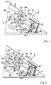
- FIG 1
- einen Teil einer Tür mit einem Halteelement für drei Türscheiben, die nicht eingebaut sind, in einer perspektivischen Ansicht,
- FIG 2
- den Teil der Tür gemäß FIG 1 mit einer in das Haltelement eingebauten Türscheibe in einer perspektivischen Ansicht,
- FIG 3
- den Teil die Tür gemäß FIG 1
und 2 mit zwei in das Halteelement eingebauten Türscheiben in einer perspektivischen Ansicht, - FIG 4
- den Teil die Tür gemäß den FIG 1
bis 3 mit drei in das Halteelement eingebauten Türscheiben in einer perspektivischen Ansicht, - FIG 5
- eine perspektivische Gesamtansicht einer Tür mit einem Halteelement gemäß FIG 3 mit zwei eingebauten Türscheiben,
- FIG 6
- einen Teil einer Tür mit einem elastischen Element für drei Türscheiben, die nicht eingebaut sind, in einer perspektivischen Ansicht,
- FIG 7
- den Teil der Tür gemäß FIG 6 mit einer gegen das elastische Element gedrückten Türscheibe in einer perspektivischen Ansicht,
- FIG 8
- den Teil der Tür gemäß FIG 6
und 7 mit zwei gegen das elastische Element gedrückten Türscheiben in einer perspektivischen Ansicht, - FIG 9
- den Teil der Tür gemäß FIG 6 bis 8 mit drei gegen das elastische Element gedrückten Türscheiben in einer Längsschnittdarstellung.
- FIG 10
- den Teil der Tür mit einem zusätzlichen Spannelement (Metallblattfeder) und einer gegen das elastische Element gedrückten Türscheibe in einer perspektivischen Ansicht.
- FIG 11
- den Teil der Tür gemäß FIG 10 mit drei gegen das elastische Element gedrückten Türscheiben und der an einer Türscheibe anliegenden gespannten Metallblattfeder in einer Längsschnittdarstellung.
- FIG. 1
- a part of a door with a holding element for three door panes, which are not installed, in a perspective view,
- FIG 2
- 1 the part of the door according to FIG. 1 with a door pane installed in the holding element in a perspective view,
- FIG 3
- 1 shows the part of the door according to FIGS. 1 and 2 with two door panes installed in the holding element in a perspective view,
- FIG 4
- the part of the door according to FIGS 1 to 3 with three door panes installed in the holding element in a perspective view,
- FIG 5
- 3 shows an overall perspective view of a door with a holding element according to FIG. 3 with two built-in door panes,
- FIG 6
- a part of a door with an elastic element for three door panes, which are not installed, in a perspective view,
- FIG 7
- 6 shows the part of the door according to FIG. 6 with a door pane pressed against the elastic element in a perspective view,
- FIG 8
- 6 shows the part of the door according to FIGS. 6 and 7 with two door panes pressed against the elastic element in a perspective view,
- FIG. 9
- the part of the door according to FIG 6 to 8 with three door panes pressed against the elastic element in a longitudinal sectional view.
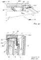
- FIG 10
- the part of the door with an additional tensioning element (metal leaf spring) and a door pane pressed against the elastic element in a perspective view.
- FIG 11
- the part of the door according to FIG 10 with three door panes pressed against the elastic element and the tensioned metal leaf spring resting on a door pane in a longitudinal sectional view.
Einander entsprechende Teile sind in den FIG 1 bis 11 mit denselben Bezugszeichen versehen.Corresponding parts are shown in FIGS. 1 to 11 provided the same reference numerals.
Die FIG 1 bis 4 zeigen ein Halteelement (Aufnahmeteil) 7 zum Halten von drei Türscheiben einer Tür, wobei in den FIG 1 bis 4 die Anzahl der Türscheiben zunimmt.1 to 4 show a holding element (receiving part) 7 for Holding three door panes of a door, wherein in FIG until 4 the number of door panes increases.
FIG 1 zeigt das Halteelement 7 mit noch keiner eingebauten
Türscheibe. Für jede der drei - in FIG 1 noch nicht dargestellten
- Türscheiben weist das Halteelement 7 eine Aufnahmenut
72, 74 bzw. 79 auf. Die Aufnahmenut 72 ist zwischen
einem ersten Begrenzungsteil 170 und einem zweiten Begrenzungsteil
171 des Halteelements 7 gebildet, die Aufnahmenut
79 zwischen dem zweiten Begrenzungsteil 171 und einem dritten
Begrenzungsteil 172 des Halteelements 7 und die dritte
Aufnahmenut 74 zwischen dem dritten Begrenzungsteil 172 und
einem vierten Begrenzungsteil 173 des Halteelements 7. In
jede der Aufnahmenuten 72, 74 und 79 ist bis zu deren Boden
174 bzw. 175 bzw. 176 in einer Einführrichtung entlang des
mit ER bezeichneten Pfeiles jeweils eine Türscheibe einführbar.
Durch die Begrenzungsteile 170 bis 173 einerseits sowie
die Böden 174 bis 176 andererseits wird eine eingeführte
Türscheibe in ihren Bewegungsfreiheitsgraden so beschränkt,
daß sie nur noch im wesentlichen parallel zu der zugehörigen
Aufnahmenut 72, 74 bzw. 79 bewegbar ist und ansonsten im
wesentlichen spielfrei gehalten ist. Zur seitlichen Begrenzung
der Bewegung der Türscheibe in einer Richtung ist ferner
an der Aufnahmenut 72 ein seitliches Begrenzungsteil 73
vorgesehen. Solche seitlichen Begrenzungsteile können auch
an den weiteren Aufnahmenuten 74 und 79, vorzugsweise in der
gleichen Richtung (an der gleichen Seite) wie das Begrenzungsteil
73 bei der Aufnahmenut 72, angeordnet sein. Im
dargestellen Ausführungsbeispiel gemäß FIG 1 sind die Aufnahmenuten
72, 74 und 79 zum Aufnehmen von Türscheiben mit
geraden Rändern, die vorzugsweise unter einem rechten Winkel
aufeinander stoßen (rechteckige Türscheiben), ausgebildet.
Die Aufnahmenuten können aber auch einer vorgegebenen Randkontur
der Türscheiben angepaßt werden, die dann auch insbesondere
konkav oder konvex gestaltet sein kann.1 shows the holding
Das Halteelement 7 weist nun gemäß den FIG 1 bis 4 eine zumindest
überwiegend quaderförmige Umhüllungsfläche auf und
ist an einer der Seiten dieser quaderförmigen Grundform offen
ausgebildet. Eine innere Seitenwand des Halteelements 7
ist mit 76 bezeichnet und eine äußere Seitenwand, deren Verlängerung
das Begrenzungsteil 73 bildet, mit 77. Die beiden
Seitenwände 76 und 77 sind über eine senkrecht dazu verlaufende
Deckwand 71, die in der Verlängerung in das Begrenzungsteil
170 übergeht, verbunden. In dem in den FIG 1 bis 4
dargestellten Ausführungsbeispiel ist das Halteelement 7 als
Hohlprofilteil ausgebildet und mit seiner von der Deckwand
71 abgewandten, offenen Seite auf ein Trägerelement 5 aufgebracht.
Die Wandung des Trägerelements 5 ist der Innenwandung
des Halteelements 7 in der Gestalt angepaßt, so daß
eine innere Seitenwand 56 des Trägerelements 5 an der Innenseite
der Seitenwand 76 des Halteelements 7, eine äußere
Seitenwand 57 des Trägerelements 5 an der äußeren Seitenwand
77 des Halteelements 7 und eine Oberseite 51 des Trägerelements
5 an der Innenseite der Deckwand 71 des Halteelements
7 zu liegen kommt. Das Halteelement 7 wird mittels an der
Innenseite seiner Wandung hervorstehenden Rastvorsprüngen 78
in entsprechende Öffnungen 58 in der Wandung des Trägerelements
5 eingerastet. In den FIG 1 bis 4 ist nur die Verrastung
der äußeren Seitenwand 77 mit des Halteelements 7 mit
der äußeren Seitenwand 57 des Trägerelements 5 zu sehen. Das
Trägerelement 5 ist nun ebenfalls als Hohlprofilteil ausgebildet,
dessen Wände 51, 56 und 57 nach Art einer Säule im
wesentlichen parallel zur Einfuhrrichtung ER verlaufen, und
dazu vorzugsweise aus einem entsprechend, insbesondere U-förmig,
profilierten Blech, vorzugsweise einem, im allgemeinen
emaillierten, Stahlblech, gebildet.According to FIGS. 1 to 4, the holding
An die Seitenwände 56 und 57 des Trägerelements 5 schließen
sich flanschartig geformte Befestigungsteile (Flanschränder)
53 und 50 an, mit denen das Trägerelement 5 über einen Kleber
99 an einer Außenscheibe 3 befestigt ist. Eine mit 59
bezeichnete Ausformung (z.B. Prägung) im Befestigungsteil 53
dient dabei zum Halten eines definierten Abstandes des Befestigungsteils
53 von der Oberfläche der Außenscheibe 3, so
daß der Kleber 99 in definierter Dicke aufgebracht werden
kann. Ähnliche Ausformungen 59 sind vorzugsweise auch im
gegenüberliegenden Befestigungsteil 50 vorgesehen. Durch die
vergleichsweise große Klebefläche des Klebers 99 werden
Kräfte vom Trägerelement 5 gleichmäßig auf die Außenscheibe
3 übertragen, so daß ein Zerspringen der Außenscheibe 3
durch thermische oder mechanische Spannungen praktisch vermieden
wird. Die Klebeverbindung 99 gewährleistet überdies
eine schonende Verbindung des Trägerelements 5 mit der Außenscheibe
3 bei der Herstellung. Es kann jedoch auch eine
Schraubverbindung, eine Rastverbindung oder eine andere Verbindung
des Trägerelements 5 mit der Außenscheibe 3 vorgesehen
sein. Close to the
Das Halteelement 7 ist als Formteil aus einer Polymerverbindung
(Polymer-Kunststoff), vorzugsweise einem thermoplastischen
oder duroplastischen Kunststoff, gebildet, wobei
alle Bestandteile, insbesondere die Begrenzungsteile 73,
170 bis 173 und die Böden 174 bis 176 der Aufnahmenuten 72,
74 bzw. 79 sowie die Seitenwände 76 und 77 und die Deckwand
71 in einem einzigen Herstellungsprozeß, insbesondere einem
Spritzgußverfahren oder einem Ziehverfahren, hergestellt
sind. Ohne Beschränkung der Allgemeinheit seien als Materialien
für das Halteelement 7 halogenierte oder nicht halogenierte
Kohlenwasserstoffpolymere genannt, beispielsweise
Polyethylen-, Polypropylen-, Polystyrol-, Polyurethan-,
Polyvinylchlorid- und Fluorcarbon-Werkstoffe sowie Copolymer-Verbindungen
mit diesen Polymeren. In den Anwendungen
bei höheren Temperaturen wie in einer Garofentür werden
entsprechend temperaturbeständige Kunststoffe gewählt.The holding
Das Halteelement 7 kann mit dem Trägerelement 5 auch beispielsweise
mit Hilfe einer Schraubverbindung lösbar verbunden
oder mittels einer Klebeverbindung unlösbar verbunden
sein.The holding
Bei dem auf dem Trägerelement 5 befestigten Halteelement 7
verlaufen die beiden am nächsten zur Außenscheibe 3 liegenden,
inneren Aufnahmenuten 74 und 79 nur bis zur inneren
Seitenwand 56 des Trägerelements 5 oder einem davor liegenden,
nicht dargestellten Begrenzungsteil des Halteelements
7. Die äußere, am weitesten entfernt von der Außenscheibe 3
liegende Aufnahmenut 72 verläuft oberhalb des Trägerelements
5 über die gesamte Breite dessen Oberseite 51 bis zum Begrenzungsteil
73, das unmittelbar an die äußere Seitenwand
57 des Trägerteils 5 anschließt. Das Halteelement 7 ist somit
von dem Trägerelement 5 praktisch über seine gesamte
Innenfläche abgestützt und dadurch stabil gehalten. With the holding
Gemäß FIG 2 ist nun in die innerste Aufnahmenut 74 eine ebene
Türscheibe 4, von der nur eine im rechten Winkel zulaufende
Ecke dargestellt ist, in der Einführrichtung ER eingeführt.
Ein unterer Rand (untere Schmalseite) 45 der Türscheibe
4 liegt auf dem Boden 176 der Aufnahmenut 74 auf.
Eine Oberseite (obere Flachseite) 41 der Türscheibe 4 liegt
an dem Begrenzungsteil 172 und eine Unterseite (untere
Flachseite) 42 an dem Begrenzungsteil 173 des Halteelements
7 an. Die zwischen den beiden Begrenzungsteilen 172 und 173
gemessene Breite der Aufnahmenut 74 ist an die zwischen der
Oberseite 41 und der Unterseite 42 der Türscheibe 4 gemessene
Scheibendicke angepaßt, so daß die Türscheibe 4 vorzugsweise
ohne Spiel in der Aufnahmenut 74 gehalten ist. Ein im
rechten Winkel zur Oberseite 41 und Unterseite 42 sowie zum
unteren Rand 45 verlaufender seitlicher Rand (seitliche
Schmalseite) 46 der Türscheibe 4 kann nun entweder an der
Seitenwand 56 des Trägerelements 5 anliegen oder von einem
nicht dargestellten seitlichen Begrenzungsteil (Abstandhalter)
der Aufnahmenut 74 von der Seitenwand 56 des Trägerelements
5 beabstandet gehalten werden. Ein solches zusätzliches
seitliches Begrenzungsteil in der Aufnahmenut 74, das
wieder an das Formteil angeformt ist, reduziert die Wärmeleitung
zwischen dem Trägerelement 5 und der Türscheibe 4
und Klappergeräusche beim sonst möglichen Anschlagen der
Türscheibe 4 an der Seitenwand 56 des Trägerelements 5.According to FIG. 2, a level is now in the innermost receiving
Gemäß FIG 3 ist nun zusätzlich zur bereits in die Aufnahmenut
74 eingeführten inneren Türscheibe 4 eine zweite Türscheibe
9 in die Aufnahmenut 79 in der Einführrichtung ER
eingeführt. Die Türscheibe 9 liegt auf dem Boden 175 der
Aufnahmenut 79 als Gegenfläche (Auflagefläche) mit ihrem
unteren Rand 95 auf und ist mit der Oberseite 91 am Begrenzungsteil
171 und der Unterseite 92 am Begrenzungsteil 172
abgestützt. Auch die Abmessung der Aufnahmenut 79 zwischen
den Begrenzungsteilen 171 und 172 entspricht etwa der Dicke
der Türscheibe 9. Der seitliche Rand 96 der Türscheibe 9
kann analog zur Türscheibe 4 gemäß FIG 2 wieder an der Seitenwand
56 des Trägerelements 5 anliegen oder von einem
nicht dargestellten seitlichen Begrenzungsteil der Aufnahmenut
79 von der Seitenwand 56 des Trägerelements 5 auf Abstand
gehalten sein.3 is now in addition to the already in the receiving
Gemäß FIG 4 ist nun eine dritte Türscheibe als Innenscheibe
2 in das Halteelement 7 eingebaut. Die Innenscheibe 2 ist in
die Aufnahmenut 72 in der Einführrichtung ER eingeführt. In
dem Halteelement 7 ist die Innenscheibe 2 in vier von sechs
Raumrichtungen gehalten durch das Begrenzungsteil 170, den
Boden 174, das Begrenzungsteil 171 sowie das seitliche Begrenzungsteil
73. Der untere Rand 25 der Innenscheibe 2
liegt am Boden 174 der Aufnahmenut 72, die Oberseite 21 an
Begrenzungsteil 170, die Unterseite 22 am Begrenzungsteil
171 sowie der seitliche Rand 26 am seitlichen Begrenzungsteil
73 an. Die Breite der Aufnahmenut 72 entspricht wieder
etwa der Dicke der Innenscheibe 2.According to FIG 4 is now a third door pane as an
Im Halteelement 7 sind also gemäß den FIG 1 bis 4 drei, insbesondere
als rechteckige Flachkörper ausgebildete, Türscheiben
4, 9 und 2 voneinander beabstandet und im wesentlichen
parallel zueinander einbaubar.According to FIGS. 1 to 4, there are three, in particular, in the holding
FIG 5 zeigt nun eine Tür mit einer Außenscheibe 3 und zwei
eingebauten Türscheiben 4 und 9. An einer Flachseite der
Außenscheibe 3 sind in einem Randbereich ein Trägerelement 5
mit einem davon getragenen Halteelement 7 gemäß den FIG 1
bis 4 sowie in einem gegenüberliegenden Randbereich ein entsprechend
ausgebildetes und parallel zum Trägerelement 5
verlaufendes Trägerelement 6, das ein entsprechend dem Halteelement
7 ausgebildetes Halteelement 8 trägt, befestigt.
Das Trägerelement 6 und das Halteelement 8 sind zumindest
weitgehend spiegelsymmetrisch bezüglich einer parallel zu
den Trägerelementen 5 und 6 und senkrecht zu der Außenscheibe
3 gerichteten Symmetrieebene zum Trägerelement 5 und dem
Halteelement 7 angeordnet und ausgebildet. Das Halteelement
8 weist analog zum Halteelement 7 eine Deckwand 81 auf der
Oberseite 61 des Trägerelements 6 und zwei von außen an den
Seitenwänden 66 und 67 des Trägerelements 6 anliegende Seitenwände
86 bzw. 87 auf. Die innere Seitenwand 86 des Halteelements
8 und die innere Seitenwand 76 des Halteelements
7 sind einander zugewandt. Auch das Halteelement 8 weist
drei Aufnahmenuten 82, 84 und 89 auf, die analog zu den Aufnahmenuten
72, 74 und 79 am Halteelement 7 ausgebildet sind.5 shows a door with an
Die Halteelemente 7 und 8 sind jeweils an den unteren Enden
der zugehörigen Trägerelemente 5 bzw. 6 angeordnet. An den
von den Halteelementen 7 und 8 abgewandten Enden der Trägerelemente
5 und 6 ist eine senkrecht zu den Trägerelementen 5
und 6 verlaufende Trägerleiste 10 in Befestigungsbereichen
155 bzw. 165 befestigt. In der Trägerleiste 10 sind elastische
Rückstellkörper (elastische Elemente) 11, 12 und 13 und
gegebenenfalls auch Montagehilfen 14 und 15 für die Montage
der Türscheiben integriert. Jeder elastische Rückstellkörper
11 bis 13 weist jeweils eine Auflagefläche (Gegenfläche,
Andrückfläche) für jede der zu montierenden oder montierten
Türscheiben 4 und 9 sowie die - nicht dargestellte - Innenscheibe
2 auf. Zur Montage werden die beiden Türscheiben 4
und 9 nacheinander zunächst in der mit EV bezeichneten vorwärts
gerichteten Einführrichtung gegen die zugehörigen Auflageflächen
der elastischen Rückstellkörper 11 bis 13 gedrückt
und entsprechend zentriert, um dann anschließend unter
der Wirkung der von den elastischen Rückstellkörpern 11
bis 13 ausgeübten rückstellenden Kräfte in der entgegengesetzten
Richtung ER in die zugehörigen Aufnahmenuten 74 und
84 bzw. 79 und 89 in den Halteelementen 7 und 8 eingeführt
zu werden. Gleichermaßen kann auch die in FIG 5 nicht dargestellte
Innenscheibe 2 montiert werden. Zum Herausnehmen der
Türscheiben 4 und 9 werden die beschriebenen Montageschritte
gerade umgekehrt, d.h. die Türscheiben 9 und 4 werden nun in
der umgekehrten Reihenfolge nacheinander gegen die rückstellende
Kraft der elastischen Rückstellkörper 11 bis 13 gedrückt
und dann aus den Aufnahmenuten 79 und 89 bzw. 74 und
84 entnommen. Die Montagehilfen 14 und 15 erleichtern die
Positionierung der Türscheiben 4 und 9 an den elastischen
Rückstellkörpern 11, 12 und 13 und in den Halteelementen 7
und 8, haben jedoch im allgemeinen keine tragende Funktion
für die Türscheiben 4 und 9. Der Aufbau und die Funktion der
elastischen Rückstellkörper 11, 12 und 13 sowie der Montagehilfen
14 und 15 wird später anhand der FIG 6 bis 9 noch
näher beschrieben.The holding
Die eingebaute innerste Türscheibe 4 sowie die eingebaute
zweitinnerste Türscheibe 9 sind in der zugehörigen Aufnahmenut
74 bzw. 79 des Halteelements 7 und der zugehörigen Aufnahmenut
84 bzw. 89 des Halteelements 8 in jeweils einem der
beiden unteren Eckbereiche sowie mit ihrem oberen Rand an
den Auflageflächen der elastischen Rückstellkörper 11 bis 13
gehalten und dazwischen freitragend. Die Halteelemente 7 und
8 sowie die elastischen Rückstellkörper 11 bis 13 bilden
gemeinsam zwei Halteeinrichtungen für die beiden Türscheiben
4 und 9 mit einer vergleichsweise geringen Kontaktfläche zu
den Türscheiben 4 und 9, so daß thermische Verluste durch
Wärmeleitung in der Tür gering gehalten werden. Beide Türscheiben
4 und 9 sind zwischen der Seitenwand 56 des Trägerelements
5 und der Seitenwand 66 des Trägerelements 6 gehalten
und von diesen in ihrer Bewegung seitlich begrenzt. The built-in
Die am weitesten außen liegenden Aufnahmenuten 72 des Halteelement
7 und 82 des Halteelements 8 sowie die elastischen
Rückstellkörper 11 bis 13 bilden auch eine Halteeinrichtung
für eine nicht dargestellte Innenscheibe 2 wie in
FIG 4. Zur Beabstandung der Innenscheibe 2 von den Trägerelementen
5 und 6 sind auf den Oberseiten 51 und 61 der
Trägerelemente 5 und 6 jeweils wenigstens ein Abstandhalter
55 bzw. 65 angeordnet, die elastisch ausgebildet sind zur
mechanischen Dämpfung der Innenscheibe und Verringerung von
Anschlagsgeräuschen, und vorzugsweise zumindest an ihrer
der Innenscheibe 2 zugewandten Oberfläche, insbesondere
durch eine Gleitbeschichtung aus Polyfluorethylen (z.B.
![]()
![]()
Als elastische Materialien für die Rückstellkörper 11 bis
13 und/oder die Abstandhalter 55 und 65 sind nun elastische
Polymere (Elastomere) auf Basis eines Kunststoffes, eines
Naturkautschuks oder einer Kunststoff-/Naturkautschuk-Verbindung
vorgesehen. Ein besonders vorteilhaftes Material
ist ein (festes) Silikon (Polysiloxan oder Polyfluorsiloxan),
das auch bei höheren Temperaturen beständig ist. Es
kann aber beispielsweise auch ein Polyurethan verwendet
werden oder ein unter dem Handelsnamen Santoprene bekannter
Kunststoff oder auch Acrylester-Elastomere, Ethylen-Propylen-Dien-Elastomere
oder Ethylen-Vinylacetat-Copolymere
oder ein unter dem Handelsnamen Hostaform vertriebener
Kunststoff (bei nicht zu hohen Temperaturanforderungen).
Weitere, vorteilhafte Elastomere sind Halogen-Kohlenstoff-Polymere,
insbesondere Fluorcarbon-Elastomere
oder Copolymere mit Fluorcarbon-Elastomeren, beispielsweise
ein Copolymer aus Tetrafluorethylen und Propylen, oder
Chlorbutadien-Elastomere. Elastomere mit Halogen(insbesondere
Fluor)-Kohlenstoff-Verbindungen sind auch
temperaturbeständiger als reine Kohlenwasserstoffe und weisen
sehr niedrige Reibungskoeffizienten auf. Der Elastizitätsmodul
(Widerstand gegen Verformung) des elastischen Materials
kann insbesondere unter etwa 5000 N/mm2, vorzugsweise
unterhalb 2000 N/mm2, gewählt werden.Elastic polymers (elastomers) based on a plastic, a natural rubber or a plastic / natural rubber compound are now provided as elastic materials for the restoring
Der Türaufbau gemäß FIG 5 zeichnet sich durch eine sehr einfache
Konstruktion mit einer geringen Zahl von Teilen aus.
Jede der im Türinnenraum liegenden Scheiben 4 und 9 sowie
die - nicht dargestellte - Innenscheibe 2 sind ohne Zuhilfenahme
von Werkzeug nur mit der Hand in der Tür montierbar
und wieder aus dieser demontierbar. Dies ermöglicht eine
sehr einfache Entnahme der Türscheiben 4, 9 und 2, insbesondere
zu Reinigungszwecken oder zum Ersatz bei Beschädigung
oder Glasbruch.The door structure according to FIG 5 is characterized by a very simple
Construction with a small number of parts.
Each of the
Die Tür ist in allen Ausführungsformen im allgemeinen zum Verschließen einer Öffnung zu einem Geräteinnenraum und insbesondere zum Verschließen einer Beschickungsöffnung eines Garofens, vorzugsweise eines Haushaltsgarofens, vorgesehen, ist aber nicht auf diese Anwendung beschränkt.In all embodiments, the door is generally for Closing an opening to a device interior and in particular to close a loading opening of a Cooking oven, preferably a household oven, provided but is not limited to this application.
Alle Türscheiben 2, 3, 4 und 9 bestehen vorzugsweise zumindest
überwiegend aus einem optisch transparenten Material,
insbesondere einem Glas oder einer Glaskeramik. Mit den
transparenten Türscheiben 3, 4, 9 und 2 ist dann ein großflächiges
Sichtfenster der Tür gebildet, um in den von der
Tür verschlossenen Geräteinnenraum, insbesondere den Ofenmuffelinnenraum
einblicken zu können.All
Insbesondere in Anwendungen, bei denen die Tür auch eine
bestimmte thermische Isolation des von ihr verschlossenen
Geräteinnenraum vom Außenraum gewährleisten muß, weisen die
Türscheiben der Tür häufig unterschiedliche physikalische
und insbesondere thermische Eigenschaften auf. Falls, wie
beispielsweise bei einem Garofen, der Innenraum auf einer
vergleichsweise hohen Temperatur liegt (beispielsweise 300°
C beim Garen und sogar bis 500° C bei einem pyrolytischen
Reinigungsprozeß), so entsteht nach dem Stefan-Boltzmann-Gesetz
bei diesen hohen Temperaturen ein vergleichsweise
hoher Anteil der Wärme in Form von Wärmestrahlung. Um diese
Wärmestrahlung im Geräteinnenraum zu halten, wird deshalb
vorzugsweise die dem Geräteinnenraum am nächsten liegende
Türscheibe, hier also die Innenscheibe 2, und gegebenenfalls
auch die weiteren Türscheiben, hier die Türscheibe 9 und
gegebenenfalls auch die Türscheibe 4, an ihrer Oberfläche
mit einer Wärmestrahlung reflektierenden Beschichtung versehen.
Ferner muß die Innenscheibe 2 einer höheren Temperatur
standhalten als die weiter außen liegenden Türscheiben 9 und
4, so daß in der Regel auch unterschiedlich temperaturbeständige
Materialien für die Innenscheibe 2, die Türscheibe
9 und die Türscheibe 4 gewählt werden.Especially in applications where the door is also a
certain thermal insulation of the closed by it
Device interior must ensure from the outside, show the
Door panes of the door often have different physical
and especially thermal properties. If how
for example in a cooking oven, the interior on a
comparatively high temperature (for example 300 °
C for cooking and even up to 500 ° C for a pyrolytic
Cleaning process), this is the result of the Stefan-Boltzmann law
a comparatively high at these high temperatures
high proportion of heat in the form of heat radiation. Around
Keeping heat radiation inside the device is therefore essential
preferably the one closest to the interior of the device
Door pane, here the
Für eine gewünschte optimale Wärmeisolationswirkung ist es
deshalb erforderlich, die Türscheiben 2, 9 und 4 immer unverwechselbar
in den jeweils vorgegebenen Positionen zu montieren.It is for a desired optimal heat insulation effect
therefore necessary, the
Die Innenscheibe 2 ist nun aufgrund ihrer zu den Türscheiben
9 und 4 unterschiedlichen Breite, gemessen senkrecht zu den
Richtungen EV und ER, und die entsprechend weiter nach außen
gehenden Aufnahmenuten 72 und 82 der Halteelemente 7 und 8
nicht mit einer der beiden Türscheiben 9 und 4 verwechselbar,
so daß sie insbesondere auch die gleiche Höhe, gemessen
parallel zu den Richtungen ER und EV, wie eine der Türscheiben
9 oder 4 aufweisen kann. Aus diesem Grunde können die
beiden Aufnahmenuten 72 und 79 gemäß den FIG 1 bis 4 (und
entsprechend die Aufnahmenuten 82 und 89 im Halteelement 8)
des Halteelements 7 auch in einer Ebene, also auf gleicher
Höhe, verlaufen.The
Um auch die Türscheiben 4 und 9 voneinander unterscheiden zu
können, sind gemäß den FIG 1 bis 5 die Türscheiben 4 und 9
in ihren Höhen, parallel zu den Richtung EV und ER gemessen,
unterschiedlich groß ausgebildet, und die elastischen Rückstellkörper
11, 12 und 13 sowie die zugehörigen Aufnahmenuten
79 und 89 sowie 74 und 84 der Halteelemente 7 bzw. 8
weisen entsprechend unterschiedliche Abstände voneinander
auf, die an die Abmessungen der Türscheiben 4 und 9 angepaßt
sind. Die Aufnahmenuten 74 des Halteelements 7 und 84 des
Halteelements 8 für die Türscheibe 4 sind dazu weiter nach
oben entgegen der Einführrichtung ER versetzt als die Aufnahmenuten
79 und 89 für die Türscheibe 9. Die Unterschiede
in den Höhen der Türscheiben 4 und 9 sollten nicht zu groß
gewählt werden, um ein ausreichend großes Sichtfenster beizubehalten
und werden im allgemeinen zwischen 2 mm und 40
mm, insbesondere zwischen 5 mm und 20 mm, gewählt. Durch
diese Maßnahmen nehmen die lateralen Flächen der Türscheiben
4, 9 und 2 von innen nach außen zu. Die innerste Türscheibe
4 ist also kleiner als die Türscheibe 9, während die Türscheibe
9 wiederum kleiner ist als die Innenscheibe 2.To distinguish the
Will man zusätzlich gewährleisten, daß einzelne oder alle
der Türscheiben 2, 4 und 9 auch immer mit derselben Oberfläche
nach innen (oder nach außen) zeigen, können die entsprechenden
Halteeinrichtungen in einer nicht dargestellten Weiterbildung,
beispielsweise durch asymmetrische Ausbildung
der Aufnahmenuten 72, 79 und 74 des Halteelements 7 im Vergleich
zu den Haltenuten 82, 89 und 84 in dem Halteelement
8, sowie die Türscheiben 2, 9 und 4 so aneinander angepaßt
sein, daß auch die Flachseiten der Türscheiben 2, 4 und 9
nicht mehr vertauscht werden können.Do you also want to ensure that individual or all
FIG 6 zeigt nun einen Ausschnitt der Tür gemäß FIG 5 in deren
rechten oberen Eckbereich. Die Türscheiben 4 und 9 sind
nicht eingebaut und deshalb auch nicht dargestellt. Dadurch
ist der elastische Rückstellkörper 13 praktisch ganz zu sehen.
Der Rückstellkörper 13 ist mit einem Elastomer-Formprofilteil
gebildet, das eine zusammenhängende Wandung
30 und mehrere Kammern (Hohlräume, Zwischenräume) 31 aufweist,
die durch jeweils einen Teilbereich (Trennwand) der
Wandung 30 voneinander getrennt sind. Im dargestellten Ausführungsbeispiel
sind die Kammern 31 an den Seiten offen und
nur parallel zur Einführrichtung EV von der Wandung 30 begrenzt.
Die Wandung 30 des elastischen Rückstellkörpers 13
umfaßt einzelne, unter bestimmten Winkeln zueinander gerichtete,
im entlasteten Zustand im wesentlichen gerade und miteinander
zusammenhängende Stege, so daß die Kammern 31 eine
im allgemeinen polyedrische Gestalt aufweisen. Der elastische
Rückstellkörper 13 ist in eine zugehörige Aufnahmetasche
23, die an der Trägerleiste 10 ausgebildet ist, eingesteckt
oder eingeklemmt und kann aus dieser leicht entnommen
werden. An dem, in Einführrichtung EV gesehen, hinteren Bereich
ist die Wandung 30 des elastischen Rückstellkörpers 13
flach ausgebildet und liegt an einer rückseitigen Flachseite
der Trägerleiste 10 an. An der entgegengesetzten Seite, die
entgegengesetzt zur Richtung EV zeigt, ist die Wandung 30
gestuft ausgebildet und weist drei ebene Auflageflächen 32,
39 und 34 mit dem Vektor EV als Normalenvektor und schräg
verlaufende Flanken 33 zwischen dem Auflagebereich 32 und
dem Auflagebereich 39 und 35 zwischen dem Auflagebereich 39
und 34 sowie im Anschluß an die Auflagefläche 34 noch eine
weitere Flanke 36 auf. Es sind nun die Auflagefläche 34 für
die Türscheibe 4, die Auflagefläche 39 für die Türscheibe 9
und die Auflagefläche 32 für die Innenscheibe 2 vorgesehen.
Die Flanken 36, 35 und 33 sind dabei zur Stabilisierung und
als Führungshilfen für die Türscheiben von Vorteil. Durch
diese Ausbildung des elastischen Rückstellkörpers 13 als
Hohlprofilteil mit mehreren Kammern wird die Federwirkung
gegenüber einem massiven Körper aus demselben (elastischen)
Material noch erheblich erhöht. Bei einem entsprechend
hochelastischen Material kann jedoch auch ein Massivkörper
als elastischer Rückstellkörper 13 verwendet werden.6 now shows a section of the door according to FIG
top right corner. The
Eine weitere Montagehilfe ist mit 14 bezeichnet und umfaßt
im wesentlichen drei parallel zueinander und voneinander
beabstandet angeordnete flache Führungselemente 141, 142 und
143. Die Trägerleiste 10 ist in ihrem Randbereich mit dem
Randbereich des Trägerelements 5 in einem Befestigungsbereich
155 verbunden, beispielsweise verschraubt oder eingeclipst.
Das Trägerelement ist wieder im Bereich des Flanschrandes
53 mit der Außenscheibe 3 verklebt.Another assembly aid is designated and includes 14
essentially three parallel to and from each other
spaced
Gemäß FIG 7 wird nun als erste Türscheibe die Türscheibe 4
in der Einführrichtung EV auf die zugehörige Auflagefläche
34 des elastischen Rückstellkörpers 13 mit einer bestimmten
Kraft gedrückt. Die auf den elastischen Rückstellkörper 13
durch die Türscheibe 4 ausgeübte Kraft führt zu einer Verformung
unterhalb der des Auflagebereichs 34 liegenden Bereiche
der Wandung 30, die durch eine gestrichelt angedeutete,
krummlinige Verformung der Stege angedeutet ist. Die
beiden Führungselemente 142 und 143 der Montagehilfe 14 dienen
dabei als Mittel zur Positionierung der Türscheibe 4,
liegen jedoch im allgemeinen bei eingeführter Türscheibe 4
nicht an der Türscheibe 4 an. Wenn die Türscheibe 4 um eine
vorgegebene Einführlänge in Richtung der Einführrichtung EV
gegen den elastischen Rückstellkörper 13 gedrückt worden
ist, kann sie an der gegenüberliegenden Seite gemäß FIG 5 in
die Aufnahmenuten 74 und 84 der Halteelemente 7 bzw. 8 eingeführt
werden und wird dann von der rückstellenden Kraft
des elastischen Rückstellkörpers 13 (sowie der weiteren elastischen
Rückstellkörper 11 und 12) in diese Aufnahmenuten
74 bzw. 84 gedrückt. Vorzugsweise sind jeder elastische
Rückstellkörper 13, die Türscheibe 4 und die Aufnahmenuten
74 und 84 so aufeinander abgestimmt, daß die Türscheibe 4 im
fertig eingebauten Zustand, wenn sie in den Aufnahmenuten 74
und 84 eingeführt ist, unter einer bestimmten Spannung gehalten
ist, der elastische Rückstellkörper 13 also unter
einer bestimmten Vorspannung steht und nicht kraftentlastet
ist und somit noch eine rückstellende Kraft auf die Türscheibe
4 auch in deren eingebautem Zustand ausübt. Dadurch
wird die Türscheibe 4 stabil zwischen den elastischen Rückstellkörpern
11 bis 13 auf der einen Seite und den Aufnahmenuten
74 und 84 auf der anderen Seite gehalten und kann
nicht klappern oder gar herausfallen.7, the
FIG 8 zeigt nun das Montieren der nächsten Türscheibe 9 am
elastischen Rückstellkörper 13. Die Türscheibe 9 wird analog
zur Türscheibe 4 gemäß FIG 7 wieder in der Einführrichtung
EV gegen die zugehörige Aufnahmefläche 39 des elastischen
Rückstellkörpers 13 gepreßt. Zur Einführung der Türscheibe 9
dienen nun die Führungselemente 141 und 142 als Führungshilfen.8 shows the assembly of the
FIG 9 veranschaulicht in einem Längsschnitt das als Hohlprofilteil
ausgebildete elastische Element 13 mit drei an zugehörigen
Auflageflächen 34, 39 und 32 eingebauten Türscheiben
4, 9 und 2. Die Verformung der Stege der Wandung 30 durch
die unter Druck eingeführten und gehaltenen Türscheiben 4, 9
und 2 aus der entlasteten Lage ist zeichnerisch angedeutet.
Durch diese elastische Verformung übt das elastische Element
13 eine rückstellende Kraft gegen die Einführrichtung EV
aus, durch die die Türscheiben 4, 9 und 2 nach unten gedrückt
werden.9 illustrates in a longitudinal section that as a hollow profile part
trained
Die unterschiedlichen Höhen der Halteeinrichtungen für die
Türscheiben 2, 4 und 9 können in allen Ausführungsformen
durch gestuft zueinander angeordnete Auflageflächen an den
elastischen Elementen 11, 12 und 13 oder an den Halteelementen
7 und 8 in Verbindung mit auf gleicher Höhe oder ebenfalls
gestuft angeordneten Auflageflächen an der anderen
Seite, also an den Halteelementen 7 und 8 bzw. den elastischen
Elementen 11, 12 und 13, verwirklicht werden.The different heights of the holding devices for the
In den FIG 1 bis 9 bilden die Halteelemente 7 und 8 einerseits
und die Rückstellkörper 11 bis 13 andererseits gemeinsam
fünf Halteeinrichtungen für die drei Türscheiben 4, 9
und 2, wobei jede Türscheibe, 2, 9 und 4 einzeln und unabhängig
von den anderen Türscheiben gehalten ist. Durch die
besondere Ausbildung der elastischen Rückstellkörper 11 bis
13 wird durch die Verformung des elastischen Rückstellkörpers
13 in der Montagereihenfolge der Türscheiben 4, 9 und
schließlich 2 jeweils die rückstellende Kraft für die einzelnen
Türscheiben erhöht, so daß auch bei der deutlich dünneren
Ausbildung des elastischen Rückstellkörpers 13 im Bereich
der Auflagefläche 32 die durch die Türscheiben 4 und 9
bewirkte Vorspannung eine ausreichende rückstellende Kraft
für die Türscheibe 2 aufzeigt.1 to 9 form the holding
FIG 10 zeigt eine alternative Ausbildung um mittels eines
eperaten Spannkörpers, hier eine Metallblattfeder 18, die
Haltekraft der Türscheibe gezielt zu erhöhen. Vorteilhafterweise
sind derartige Spannelemente gleichmäßig über die gesamte
Breite der Türscheibe symmetrisch verteilt. Es kann
aber auch nur eine Metallblattfeder mittig oder in der Nähe
des Rückstellkörpers 12 (FIG 5) vorgesehen sein. Der zusätzliche
bzw. alternative Spannkörper ist seinerseits an der
Trägerleiste 10 aufgesteckt, verschraubt, vernietet oder
z.B. aufgeklebt. Das Montieren der zugehörigen Türscheibe,
im dargestellten Ausführungsfall ist dies die Türscheibe 2,
am elastischen Rückstellkörper 13 und zusätzlich am seperaten
Spannkörper, der Metallblattfeder 18, wird analog zur
Türscheibe 4 gemäß FIG 7 wieder in der Einführrichtung EV
gegen die zugehörige Aufnahmefläche 32 des elastischen Rückstellkörpers
13 und der zusätzlichen Metallblattfederfläche
181 gepresst. Als Einführungshilfe kann das hier nicht abgebildete
Führungselement 141 (FIG 8) und die Rahmeninnenfläche
144 der Trägerleiste 10 (FIG 11) dienen. In FIG 10 ebenfalls
nicht abgebildet sind die aus z.B. den FIG 6 und FIG 7
bekannten Führungselementen (141, 142, 143) der Montagehilfe
14, die aber selbstverständlich auch hier vorgesehen sein
können.10 shows an alternative embodiment by means of a
separate clamping body, here a
FIG 11 verdeutlicht in einem Längsschnitt A-A durch die gespannte
Metallblattfeder 18, mit der Metallblattfederfläche
181, sowie den im Hintergrund zu erkennenden Rückstellkörper
12 (der aus FIG 5 bekannt ist und in FIG 10 in Richtung der
Schnittansicht A-A liegt) mit den drei dazugehörigen Auflageflächen
34, 39 und 32. Wie bereits beschrieben, üben die
Auflageflächen auf die eingebauten Türscheiben 4, 9 und 2
durch ihre elastische Verformung eine rückstellende Kraft
gegen die Einführrichtung EV aus, durch die die Türscheiben
4, 9 und 2 gegen das Halteelement 7 gedrückt werden. FIG 11 illustrates in a longitudinal section A-A through the tensioned
Durch eine besonders vorteilhafte Ausbildung der Metallblattfeder
18 kann der Steg 145 der Trägerleiste 10 derart
ummantelt werden, dass der Steg 145 (z.B. Duroplast, spröde)
durch die Metallblattfeder (Federstahl, hochzäh) körperlich
geschützt wird. Durch das Einbringen einer Sicke auf der
Metallblattfederfläche 182 kann die Kontaktfläche zu eingesetzter
Türscheibe (hier 4) mit Türscheiben-Fläche 41 sehr
klein gehalten werden, damit z.B. ein thermischer Übergang
eines möglichen Temperaturgefälles sehr gering bleibt.Through a particularly advantageous design of the
Für alle beschriebenen Ausführungsbeispiele gilt, dass die
Türscheiben 4, 9 und 2 immer in der vorgegebenen Reihenfolge
von innen nach außen einzubauen sowie von außen nach innen
auszubauen sind.For all of the exemplary embodiments described, the
Anstelle eines oder mehrerer Rückstellkörper für jeweils mehrere Türscheiben können auch für jede Türscheibe ein oder mehrere gesonderte Rückstellkörper vorgesehen sein.Instead of one or more reset bodies for each Several door panes can also be used for each door pane several separate return bodies can be provided.
Eine Unverwechselbarkeit der Türscheiben kann zusätzlich oder alternativ auch durch unterschiedliche Dicken der Türscheiben und entsprechend unterschiedliche Breiten der dazugehörigen Aufnahmenuten erreicht werden.A distinctive character of the door panes can also be or alternatively through different thicknesses of the door panes and correspondingly different widths of the corresponding ones Recording grooves can be reached.
Claims (27)
wobei
in which
Applications Claiming Priority (4)
| Application Number | Priority Date | Filing Date | Title |
|---|---|---|---|
| DE29914007U | 1999-08-11 | ||
| DE29914007U DE29914007U1 (en) | 1999-08-11 | 1999-08-11 | Door for a device, in particular a cooking oven, with unmistakably mountable panes |
| DE19941273 | 1999-08-31 | ||
| DE19941273 | 1999-08-31 |
Publications (3)
| Publication Number | Publication Date |
|---|---|
| EP1076210A2 true EP1076210A2 (en) | 2001-02-14 |
| EP1076210A3 EP1076210A3 (en) | 2003-07-09 |
| EP1076210B1 EP1076210B1 (en) | 2013-06-26 |
Family
ID=26054774
Family Applications (1)
| Application Number | Title | Priority Date | Filing Date |
|---|---|---|---|
| EP20000117143 Expired - Lifetime EP1076210B1 (en) | 1999-08-11 | 2000-08-10 | Door for a device, particularly an oven, with elastic return bodies for holding the plates |
Country Status (2)
| Country | Link |
|---|---|
| EP (1) | EP1076210B1 (en) |
| ES (1) | ES2425936T3 (en) |
Cited By (17)
| Publication number | Priority date | Publication date | Assignee | Title |
|---|---|---|---|---|
| DE10219349A1 (en) * | 2002-04-30 | 2003-11-20 | Bsh Bosch Siemens Hausgeraete | Door for cooking oven has intermediate pane lockable by locking device with two positions |
| DE10336138B3 (en) * | 2003-08-04 | 2004-10-14 | Miele & Cie. Kg | Door for household equipment has clamping parts movable to locking position and panels fitted with play between elastic part and holding part |
| EP1215443A3 (en) * | 2000-12-12 | 2005-07-27 | AEG Hausgeräte GmbH | Retaining device for at least one door window, especially for an oven door window |
| WO2006059303A2 (en) * | 2004-12-01 | 2006-06-08 | Arcelik Anonim Sirketi | A cooking appliance |
| DE102005044694A1 (en) * | 2005-09-19 | 2007-03-22 | BSH Bosch und Siemens Hausgeräte GmbH | High-level cooking appliance |
| DE102005004944B4 (en) * | 2003-08-04 | 2007-05-16 | Miele & Cie | Door for a household appliance with removable disc |
| EP1850072A2 (en) | 2006-04-24 | 2007-10-31 | LG Electronics Inc. | Oven door |
| EP2075509A1 (en) * | 2007-12-28 | 2009-07-01 | Vestel Beyaz Esya Sanayi Ve Ticaret A.S. | Oven door |
| ES2388975A1 (en) * | 2010-01-29 | 2012-10-22 | Fagor S. Coop. | Door adapted to close a cooking chamber of a domestic oven. (Machine-translation by Google Translate, not legally binding) |
| WO2014048814A1 (en) * | 2012-09-26 | 2014-04-03 | BSH Bosch und Siemens Hausgeräte GmbH | Door for a domestic appliance and domestic appliance for preparing foods having a door |
| WO2014102116A1 (en) * | 2012-12-28 | 2014-07-03 | Arcelik Anonim Sirketi | A door comprising detachable panels and an oven wherein the door is used |
| EP1647775A3 (en) * | 2004-10-13 | 2015-05-27 | LG Electronics, Inc. | Oven with glass supporting structure |
| WO2015096865A1 (en) * | 2013-12-24 | 2015-07-02 | Arcelik Anonim Sirketi | Door for use in a household appliance and household appliance having the same |
| US20160195278A1 (en) * | 2013-10-31 | 2016-07-07 | Electrolux Appliances Aktiebolag | Glass package and framework for an oven door of a cooking oven |
| EP3299723A1 (en) * | 2016-09-26 | 2018-03-28 | Electrolux Appliances Aktiebolag | Oven door for a cooking oven |
| US10520201B2 (en) | 2014-09-05 | 2019-12-31 | Electrolux Appliances Aktiebolag | Glass package and framework for an oven door of a cooking oven |
| EP2634493B1 (en) * | 2012-02-28 | 2021-07-21 | BSH Hausgeräte GmbH | Door for a domestic appliance for preparing food with a support element |
Citations (5)
| Publication number | Priority date | Publication date | Assignee | Title |
|---|---|---|---|---|
| DE2654017A1 (en) | 1975-11-28 | 1977-06-02 | Mills Prod Inc | CLOSED WINDOW UNIT FOR INSTALLATION IN AN OVEN DOOR |
| DE7736544U1 (en) | 1977-11-30 | 1978-03-09 | Metallwerke Gebr. Seppelfricke Gmbh, 4650 Gelsenkirchen | OVEN DOOR WITH VIEWING WINDOW FOR HOUSEHOLD STOVES OR DGL. |
| EP0811806A1 (en) | 1996-06-05 | 1997-12-10 | AEG Hausgeräte GmbH | Door for closing the muffle of a baking oven |
| DE19705120A1 (en) | 1997-02-11 | 1998-08-13 | Gaggenau Hausgeraete Gmbh | Oven door |
| EP0900987A1 (en) | 1997-09-03 | 1999-03-10 | AEG Hausgeräte GmbH | Door for a home appliance, especially a houshold cooking stove |
Family Cites Families (4)
| Publication number | Priority date | Publication date | Assignee | Title |
|---|---|---|---|---|
| GB451702A (en) * | 1935-02-13 | 1936-08-11 | Charles Reginald Belling | Improvements in and relating to cooking ovens and the like |
| DE19738505C1 (en) * | 1997-09-03 | 1999-03-18 | Aeg Hausgeraete Gmbh | Door for a household appliance, in particular a household oven |
| DE19738506C1 (en) * | 1997-09-03 | 1999-03-18 | Aeg Hausgeraete Gmbh | Door for domestic oven |
| DE29914007U1 (en) * | 1999-08-11 | 1999-10-21 | Aeg Hausgeraete Gmbh | Door for a device, in particular a cooking oven, with unmistakably mountable panes |
-
2000
- 2000-08-10 ES ES00117143T patent/ES2425936T3/en not_active Expired - Lifetime
- 2000-08-10 EP EP20000117143 patent/EP1076210B1/en not_active Expired - Lifetime
Patent Citations (5)
| Publication number | Priority date | Publication date | Assignee | Title |
|---|---|---|---|---|
| DE2654017A1 (en) | 1975-11-28 | 1977-06-02 | Mills Prod Inc | CLOSED WINDOW UNIT FOR INSTALLATION IN AN OVEN DOOR |
| DE7736544U1 (en) | 1977-11-30 | 1978-03-09 | Metallwerke Gebr. Seppelfricke Gmbh, 4650 Gelsenkirchen | OVEN DOOR WITH VIEWING WINDOW FOR HOUSEHOLD STOVES OR DGL. |
| EP0811806A1 (en) | 1996-06-05 | 1997-12-10 | AEG Hausgeräte GmbH | Door for closing the muffle of a baking oven |
| DE19705120A1 (en) | 1997-02-11 | 1998-08-13 | Gaggenau Hausgeraete Gmbh | Oven door |
| EP0900987A1 (en) | 1997-09-03 | 1999-03-10 | AEG Hausgeräte GmbH | Door for a home appliance, especially a houshold cooking stove |
Cited By (24)
| Publication number | Priority date | Publication date | Assignee | Title |
|---|---|---|---|---|
| EP1215443A3 (en) * | 2000-12-12 | 2005-07-27 | AEG Hausgeräte GmbH | Retaining device for at least one door window, especially for an oven door window |
| DE10219349B4 (en) * | 2002-04-30 | 2004-12-30 | BSH Bosch und Siemens Hausgeräte GmbH | Door for a device, especially for a cooking oven |
| DE10219349A1 (en) * | 2002-04-30 | 2003-11-20 | Bsh Bosch Siemens Hausgeraete | Door for cooking oven has intermediate pane lockable by locking device with two positions |
| EP1505352A3 (en) * | 2003-08-04 | 2008-03-12 | Miele & Cie. KG | Household appliance door with removable plate |
| DE10336138B3 (en) * | 2003-08-04 | 2004-10-14 | Miele & Cie. Kg | Door for household equipment has clamping parts movable to locking position and panels fitted with play between elastic part and holding part |
| EP1505352A2 (en) | 2003-08-04 | 2005-02-09 | Miele & Cie. KG | Household appliance door with removable plate |
| DE102005004944B4 (en) * | 2003-08-04 | 2007-05-16 | Miele & Cie | Door for a household appliance with removable disc |
| EP1647775A3 (en) * | 2004-10-13 | 2015-05-27 | LG Electronics, Inc. | Oven with glass supporting structure |
| WO2006059303A2 (en) * | 2004-12-01 | 2006-06-08 | Arcelik Anonim Sirketi | A cooking appliance |
| WO2006059303A3 (en) * | 2004-12-01 | 2007-04-26 | Arcelik As | A cooking appliance |
| DE102005044694A1 (en) * | 2005-09-19 | 2007-03-22 | BSH Bosch und Siemens Hausgeräte GmbH | High-level cooking appliance |
| EP1850072A2 (en) | 2006-04-24 | 2007-10-31 | LG Electronics Inc. | Oven door |
| EP1850072A3 (en) * | 2006-04-24 | 2013-07-17 | LG Electronics Inc. | Oven door |
| EP2075509A1 (en) * | 2007-12-28 | 2009-07-01 | Vestel Beyaz Esya Sanayi Ve Ticaret A.S. | Oven door |
| ES2388975A1 (en) * | 2010-01-29 | 2012-10-22 | Fagor S. Coop. | Door adapted to close a cooking chamber of a domestic oven. (Machine-translation by Google Translate, not legally binding) |
| EP2634493B1 (en) * | 2012-02-28 | 2021-07-21 | BSH Hausgeräte GmbH | Door for a domestic appliance for preparing food with a support element |
| WO2014048814A1 (en) * | 2012-09-26 | 2014-04-03 | BSH Bosch und Siemens Hausgeräte GmbH | Door for a domestic appliance and domestic appliance for preparing foods having a door |
| WO2014102116A1 (en) * | 2012-12-28 | 2014-07-03 | Arcelik Anonim Sirketi | A door comprising detachable panels and an oven wherein the door is used |
| CN105408693A (en) * | 2012-12-28 | 2016-03-16 | 阿塞里克股份有限公司 | A door comprising detachable panels and an oven wherein the door is used |
| US20160195278A1 (en) * | 2013-10-31 | 2016-07-07 | Electrolux Appliances Aktiebolag | Glass package and framework for an oven door of a cooking oven |
| WO2015096865A1 (en) * | 2013-12-24 | 2015-07-02 | Arcelik Anonim Sirketi | Door for use in a household appliance and household appliance having the same |
| US10520201B2 (en) | 2014-09-05 | 2019-12-31 | Electrolux Appliances Aktiebolag | Glass package and framework for an oven door of a cooking oven |
| EP3299723A1 (en) * | 2016-09-26 | 2018-03-28 | Electrolux Appliances Aktiebolag | Oven door for a cooking oven |
| WO2018054656A1 (en) * | 2016-09-26 | 2018-03-29 | Electrolux Appliances Aktiebolag | Oven door for a cooking oven |
Also Published As
| Publication number | Publication date |
|---|---|
| ES2425936T3 (en) | 2013-10-18 |
| EP1076210B1 (en) | 2013-06-26 |
| EP1076210A3 (en) | 2003-07-09 |
Similar Documents
| Publication | Publication Date | Title |
|---|---|---|
| EP1076210A2 (en) | Door for a device, particularly an oven, with elastic return bodies for holding the plates | |
| EP1079180B1 (en) | Door for a device, particularly an oven, with non-interchangeable mountable plates | |
| EP1081437B1 (en) | Door for a device, in particular an oven, with panel support for several panels | |
| DE10336138B3 (en) | Door for household equipment has clamping parts movable to locking position and panels fitted with play between elastic part and holding part | |
| EP0857918A1 (en) | Door for a baking oven | |
| DE102016224743A1 (en) | Haushaltsgargerät | |
| EP2010031B1 (en) | Door for a refrigerating unit | |
| EP1106932B1 (en) | Oven door with supporting elements made of plastic material | |
| EP1069378B1 (en) | Door for a device, especially a baking oven | |
| EP1126126A1 (en) | Oven door with window and operating handle | |
| DE19738505C1 (en) | Door for a household appliance, in particular a household oven | |
| DE10219349B4 (en) | Door for a device, especially for a cooking oven | |
| WO2017137239A1 (en) | Domestic appliance device | |
| DE202007013355U1 (en) | Device for adjusting a floor or shelf of a refrigerator and / or freezer | |
| EP1555486A2 (en) | Oven door | |
| EP1178264B1 (en) | Door for domestic appliance, in particular for cooking oven | |
| EP4185814A1 (en) | Door and domestic cooking device | |
| EP1548367B1 (en) | Device for closing the cavity opening of a household appliance | |
| EP1308676A2 (en) | Cooking oven door | |
| EP2876235A1 (en) | Lock assembly for sliding doors and windows | |
| EP1431672A2 (en) | Household meal-warming device or similar | |
| EP1464898A1 (en) | Cooking device | |
| EP1172614B1 (en) | Door for domestic appliance, in particular for cooking oven | |
| EP3339556B1 (en) | Closure assembly for building components | |
| DE102021204626A1 (en) | Door for a kitchen utensil and kitchen utensil with such a door |
Legal Events
| Date | Code | Title | Description |
|---|---|---|---|
| PUAI | Public reference made under article 153(3) epc to a published international application that has entered the european phase |
Free format text: ORIGINAL CODE: 0009012 |
|
| AK | Designated contracting states |
Kind code of ref document: A2 Designated state(s): AT BE CH CY DE DK ES FI FR GB GR IE IT LI LU MC NL PT SE |
|
| AX | Request for extension of the european patent |
Free format text: AL;LT;LV;MK;RO;SI |
|
| PUAL | Search report despatched |
Free format text: ORIGINAL CODE: 0009013 |
|
| AK | Designated contracting states |
Designated state(s): AT BE CH CY DE DK ES FI FR GB GR IE IT LI LU MC NL PT SE |
|
| AX | Request for extension of the european patent |
Extension state: AL LT LV MK RO SI |
|
| 17P | Request for examination filed |
Effective date: 20030530 |
|
| AKX | Designation fees paid |
Designated state(s): DE ES FR GB IT SE |
|
| 17Q | First examination report despatched |
Effective date: 20080110 |
|
| RAP1 | Party data changed (applicant data changed or rights of an application transferred) |
Owner name: ELECTROLUX ROTHENBURG GMBH FACTORY AND DEVELOPMENT |
|
| GRAP | Despatch of communication of intention to grant a patent |
Free format text: ORIGINAL CODE: EPIDOSNIGR1 |
|
| GRAS | Grant fee paid |
Free format text: ORIGINAL CODE: EPIDOSNIGR3 |
|
| GRAA | (expected) grant |
Free format text: ORIGINAL CODE: 0009210 |
|
| AK | Designated contracting states |
Kind code of ref document: B1 Designated state(s): DE ES FR GB IT SE |
|
| REG | Reference to a national code |
Ref country code: GB Ref legal event code: FG4D Free format text: NOT ENGLISH |
|
| REG | Reference to a national code |
Ref country code: DE Ref legal event code: R096 Ref document number: 50016327 Country of ref document: DE Effective date: 20130822 |
|
| REG | Reference to a national code |
Ref country code: ES Ref legal event code: FG2A Ref document number: 2425936 Country of ref document: ES Kind code of ref document: T3 Effective date: 20131018 |
|
| PG25 | Lapsed in a contracting state [announced via postgrant information from national office to epo] |
Ref country code: SE Free format text: LAPSE BECAUSE OF FAILURE TO SUBMIT A TRANSLATION OF THE DESCRIPTION OR TO PAY THE FEE WITHIN THE PRESCRIBED TIME-LIMIT Effective date: 20130626 |
|
| PGFP | Annual fee paid to national office [announced via postgrant information from national office to epo] |
Ref country code: ES Payment date: 20130829 Year of fee payment: 14 |
|
| PLBE | No opposition filed within time limit |
Free format text: ORIGINAL CODE: 0009261 |
|
| STAA | Information on the status of an ep patent application or granted ep patent |
Free format text: STATUS: NO OPPOSITION FILED WITHIN TIME LIMIT |
|
| 26N | No opposition filed |
Effective date: 20140327 |
|
| REG | Reference to a national code |
Ref country code: DE Ref legal event code: R097 Ref document number: 50016327 Country of ref document: DE Effective date: 20140327 |
|
| PGFP | Annual fee paid to national office [announced via postgrant information from national office to epo] |
Ref country code: DE Payment date: 20140821 Year of fee payment: 15 |
|
| PGFP | Annual fee paid to national office [announced via postgrant information from national office to epo] |
Ref country code: GB Payment date: 20140820 Year of fee payment: 15 |
|
| PGFP | Annual fee paid to national office [announced via postgrant information from national office to epo] |
Ref country code: IT Payment date: 20140827 Year of fee payment: 15 |
|
| REG | Reference to a national code |
Ref country code: FR Ref legal event code: PLFP Year of fee payment: 16 |
|
| PGFP | Annual fee paid to national office [announced via postgrant information from national office to epo] |
Ref country code: FR Payment date: 20150626 Year of fee payment: 16 |
|
| REG | Reference to a national code |
Ref country code: ES Ref legal event code: FD2A Effective date: 20150925 |
|
| PG25 | Lapsed in a contracting state [announced via postgrant information from national office to epo] |
Ref country code: ES Free format text: LAPSE BECAUSE OF NON-PAYMENT OF DUE FEES Effective date: 20140811 |
|
| REG | Reference to a national code |
Ref country code: DE Ref legal event code: R119 Ref document number: 50016327 Country of ref document: DE |
|
| GBPC | Gb: european patent ceased through non-payment of renewal fee |
Effective date: 20150810 |
|
| PG25 | Lapsed in a contracting state [announced via postgrant information from national office to epo] |
Ref country code: IT Free format text: LAPSE BECAUSE OF NON-PAYMENT OF DUE FEES Effective date: 20150810 |
|
| PG25 | Lapsed in a contracting state [announced via postgrant information from national office to epo] |
Ref country code: GB Free format text: LAPSE BECAUSE OF NON-PAYMENT OF DUE FEES Effective date: 20150810 Ref country code: DE Free format text: LAPSE BECAUSE OF NON-PAYMENT OF DUE FEES Effective date: 20160301 |
|
| REG | Reference to a national code |
Ref country code: FR Ref legal event code: ST Effective date: 20170428 |
|
| PG25 | Lapsed in a contracting state [announced via postgrant information from national office to epo] |
Ref country code: FR Free format text: LAPSE BECAUSE OF NON-PAYMENT OF DUE FEES Effective date: 20160831 |