EP1075552B1 - Installation automatique en continu pour le traitement et la coloration des bords et des languettes de lanières en cuir ou matière synthétique - Google Patents
Installation automatique en continu pour le traitement et la coloration des bords et des languettes de lanières en cuir ou matière synthétique Download PDFInfo
- Publication number
- EP1075552B1 EP1075552B1 EP98929620A EP98929620A EP1075552B1 EP 1075552 B1 EP1075552 B1 EP 1075552B1 EP 98929620 A EP98929620 A EP 98929620A EP 98929620 A EP98929620 A EP 98929620A EP 1075552 B1 EP1075552 B1 EP 1075552B1
- Authority
- EP
- European Patent Office
- Prior art keywords
- colouring
- roller
- rollers
- strips
- strip
- Prior art date
- Legal status (The legal status is an assumption and is not a legal conclusion. Google has not performed a legal analysis and makes no representation as to the accuracy of the status listed.)
- Expired - Lifetime
Links
- 238000004040 coloring Methods 0.000 title claims description 152
- 238000009434 installation Methods 0.000 title claims description 28
- 238000012545 processing Methods 0.000 title claims description 23
- 239000010985 leather Substances 0.000 title claims description 5
- 229920002994 synthetic fiber Polymers 0.000 title claims description 3
- 238000012546 transfer Methods 0.000 claims description 9
- 238000001035 drying Methods 0.000 claims description 8
- 239000000463 material Substances 0.000 claims description 6
- 230000001680 brushing effect Effects 0.000 claims description 5
- 238000013519 translation Methods 0.000 claims description 5
- 230000005540 biological transmission Effects 0.000 claims description 4
- 229910003460 diamond Inorganic materials 0.000 claims description 4
- 239000010432 diamond Substances 0.000 claims description 4
- ZZUFCTLCJUWOSV-UHFFFAOYSA-N furosemide Chemical compound C1=C(Cl)C(S(=O)(=O)N)=CC(C(O)=O)=C1NCC1=CC=CO1 ZZUFCTLCJUWOSV-UHFFFAOYSA-N 0.000 claims description 4
- 238000003780 insertion Methods 0.000 claims description 4
- 230000037431 insertion Effects 0.000 claims description 4
- 239000000843 powder Substances 0.000 claims description 4
- 238000010521 absorption reaction Methods 0.000 claims description 3
- 238000000034 method Methods 0.000 claims description 3
- 230000001105 regulatory effect Effects 0.000 claims description 3
- 230000000694 effects Effects 0.000 claims description 2
- 230000005484 gravity Effects 0.000 claims description 2
- 230000036316 preload Effects 0.000 claims description 2
- 230000000284 resting effect Effects 0.000 claims description 2
- 239000011248 coating agent Substances 0.000 description 2
- 238000000576 coating method Methods 0.000 description 2
- 238000003825 pressing Methods 0.000 description 2
- 239000002699 waste material Substances 0.000 description 2
- 230000002301 combined effect Effects 0.000 description 1
- 238000013461 design Methods 0.000 description 1
- 230000006866 deterioration Effects 0.000 description 1
- 230000001788 irregular Effects 0.000 description 1
- 239000003973 paint Substances 0.000 description 1
- 238000009958 sewing Methods 0.000 description 1
- 230000002226 simultaneous effect Effects 0.000 description 1
- 125000006850 spacer group Chemical group 0.000 description 1
Images

Classifications
-
- C—CHEMISTRY; METALLURGY
- C14—SKINS; HIDES; PELTS; LEATHER
- C14B—MECHANICAL TREATMENT OR PROCESSING OF SKINS, HIDES OR LEATHER IN GENERAL; PELT-SHEARING MACHINES; INTESTINE-SPLITTING MACHINES
- C14B17/00—Details of apparatus or machines for manufacturing or treating skins, hides, leather, or furs
- C14B17/06—Work feeding or clamping devices
-
- C—CHEMISTRY; METALLURGY
- C14—SKINS; HIDES; PELTS; LEATHER
- C14B—MECHANICAL TREATMENT OR PROCESSING OF SKINS, HIDES OR LEATHER IN GENERAL; PELT-SHEARING MACHINES; INTESTINE-SPLITTING MACHINES
- C14B11/00—Finishing the edges of leather pieces, e.g. by folding, by burning
-
- C—CHEMISTRY; METALLURGY
- C14—SKINS; HIDES; PELTS; LEATHER
- C14B—MECHANICAL TREATMENT OR PROCESSING OF SKINS, HIDES OR LEATHER IN GENERAL; PELT-SHEARING MACHINES; INTESTINE-SPLITTING MACHINES
- C14B9/00—Making driving belts or other leather belts or strips
Definitions
- the strip In automatic installations for treating belts or other strips of leather or of other materials, especially for cutting and colouring the edges, the strip is laid flat and is carried forward by rollers pressing on either side.
- the belts are cut from a leather disk and, after various processes, are cleaned, shaped to the required cross section, smoothed and hardened under pull from opposing rollers that therefore operate "flat" on the two faces of the belt.
- Subject of the invention is an automatic installation for treating belts and other strip-like pieces of leather or synthetic material.
- this installation comprises all or part and various combinations of means for pulling and guiding the strips along the processing line, operating laterally on the edges of the strips, means for treating the lateral edges and tip of strips compring cutting means, brushing means, colouring means consisting of a tapered roller the axis of which is inclined and the lower end of which is immersed in a vat of colour that becomes transferred to a colouring roller which finally makes contact with the edges or the tip of the strips, means for drying and means for gathering up the finished product.
- the means that pull and guide the strips are pairs of replaceable rollers to treat strips of practically any size and material, with edges of any shape and for obtaining the various desired effects, with a substantially V-shaped groove into which the edges of the strips are fitted.
- the set of rollers is motor-driven and the rollers rotate freely in pairs of heads, at the front and back in relation to the strip forward movement, opposite one another on the working line and replaceable, supported by surface plates which in turn rest on the upper surface of the means for treating the side edges of the strips.
- Said surface plates slide, transversally to the working line, on both sides, operated by a mechanism worked by a handle or other means, so that the reciprocal distance can be decided at will between the corresponding parts of the pairs of pulling and guiding rollers, to suit it to the width and type of strip to be treated and produced.
- the cutting and brushing means are pairs of discoid cutters and brushes placed on the surface of the machine and aligned on either side of the processing line, between the two sets, front and back, of pulling and guiding rollers placed respectively in the pairs of front and back heads.
- the various pairs of rollers in the front heads have circumferential knurled grooves while the pairs of rollers in the rear heads have circumferential smooth grooves.
- the colouring means comprises an oblong plate at one end of which a short shaft, resting on a ball bearing, is fixed above to a pulley and, below the plate, to a colouring roller in which there is a circumferential groove to be aligned and brought in contact with the edge of the strip.
- the end of a small plate is placed in a seat made for it on the outer lateral rear end of each plate, this small plate freely turning round a connecting pin at whose free end a bearing supports the short shaft of a tapered roller.
- the small plate is inclined in relation to the other plate at an angle substantially equal to the taper of said tapered roller which places its tapered surface in contact, according to a vertical line, with the colouring roller.
- At the position occupied by said colouring roller is a small vat of colour into which the lower end of the tapered roller dips, the colour it picks up being then transferred by contact to the colouring roller.
- Adherence between the tapered roller and the colouring roller is ensured by an elastic ring or similar means, supported by two pins fixed respectively to the plate and to one side of the small plate.
- the colouring device comprises a short arm applied to the pulley shaft between the plate and the colouring roller by insertion of said shaft in a hole passing through said arm.
- a downward-facing bracket that, freely rotating, supports a small oblong roller at whose upper end is a groove at the same level as that of a pulley fitted between said arm and the colouring roller and fixed to said shaft.
- a continuous band connects said groove with this latter pulley.
- Said small roller is pressed against the advancing strip along the line of work, by a pressing means consisting of a cord with a counterweight at one end, said cord passing over a transmission and then connecting with the above arm at some distance from its centre of rotation.
- the tapered roller is high enough to contact both the colouring roller and the pulley above said roller.
- the counterweights produce a thrust tending to create contact between the two small colouring rollers of the device, ensuring contact between the lower groove in said pair of small rollers and the tip of the advancing strip thus automatically colouring the tip.
- the means for collecting finished strips consists of a machine comprising a continuous horizontal band, aligned with the advancing line of strips and of at least one pair of transversal thrust means for the strip that reaches said continuous band, operated by a motor-driven mechanism whose motor is turned on when an electric circuit is closed by a microswitch as soon as it is hit by the tip of an advancing strip.
- Said thrust means determines transfer of the strip from the continuous band onto a set of parallel continuous bands stretched between two opposite shafts that lie below said continuous band and across it.
- a chute At the free end of said set of bands is a a chute with flat terminal area so that, by translation of the short bands, each strip is moved from the continuous band to said chute and the strips become piled up on said terminal area.
- the mechanism that controls the thrust means comprises a pair of racks, crosswise to the continuous band, against which pinions press supported by a shaft with an electric motor on its end.
- a grooved bar is mounted at the ends of the racks, at the position of the continuous band, the thrust means taking up a position along the groove in the bar, according to the length of the strip on the working line.
- means is applied to the rear of the upper surface of the means for treating the lateral edges and tip of the strip.
- the oblong plates are mounted, free to rotate, on vertical pins placed on the front of said plates and towards the back of the rear heads that carry the pulling and guiding rollers.
- the last pair of said rollers has an upward extension forming cylindrical bodies with a terminal pulley at the end connected, by a continuous band, to the pulley fixed to the colouring roller.
- Said plates are pressed together by an arm placed at their lower ends at which there is a screw to whose shank a helical spring is fixedly connected at the other end to a hooking means placed on the surface plates of the machine.
- spring tension can be adjusted to ensure continuous contact between the colouring rollers on the pair of plates and the advancing strip whose edges then receive the colour.
- a pair of colouring means is mounted on the rear end of the upper surface of the means for treating the lateral edges and tip of the strip.
- the oblong plates turn freely on vertical pins placed on the front of said plates and on the rear side of the rear heads that carry the pulliny and guiding rollers.
- the last pair of said rollers extend upwards forming cylindrical bodies with a terminal pulley, these cylindrical bodies being joined, by a continuous band to the pulley fixed to the colouring roller.
- Said plates are pressed against each other by an arm at their lower ends that carry a screw on whose shank a helical spring is fixedly connected to the other end by a hooking means on the surface plates of the machine.
- spring tension can be adjusted by turning the screw, ensuring continuous contact by the colouring rollers and the small colouring rollers, supported by arms mounted on the short shaft of the colouring roller on the pair of plates, against the advancing strip so that the colouring rollers colour its edges and the small colouring rollers colour its tip.
- the means for colouring the edges around the tip consist of a device placed at the rear end of the collecting machine, comprising a colouring unit formed of a slide that moves crosswise to the strips forward movement on supports fixed to the machine.
- a vertical column On said slide is a vertical column that supports a large horizontal plate sliding freely round a shaft and supporting, at its opposite end, a colouring device.
- the upper pulley of the colouring roller is connected by a band to a vertical electric motor carried by said slide.
- a means for moving is provided for the slide, said means being a piston of a horizontal cylinder.
- a presser operated by a vertical fluidic cylinder, stops and holds a strip, as soon as it passes from the continuous band to the transversal bands, so causing simultaneous stoppage of said bands.
- the initial position of the colouring roller is at one side of the tip of the strip now stopped, so that by operating the piston in the cylinder on the slide the colouring roller is obliged to move round the tip aided by action of the helical spring on the column supporting the colouring device.
- the tip is thus coloured by the combined effect of movement of the slide and rotation of the colouring unit round the column.
- a bracket on the large plate that supports the colouring unit is a wheel that will match with a substantially arched cam on a wall opposite said wheel fixed to the structure of the machine.
- Size and positions of wheel and cam are such that when a stroke is made by the colouring unit in both directions during colouring, the wheel pursues the cam creating a trajectory for the colouring unit that corresponds to the outline of the cam.
- Action of said cam is concomitant with movement of the colouring roller round the tip of the strip.
- the tips of the strip when coloured pass on towards a chute, passing through a jet of warm air from a hole in a surface below said tips and generated by fans and by an electric resistance, guided onto the tips by a curved screen which rises from one edge of the hole and curves towards the translating tips.
- the surface of the grooves in the colouring rollers and small colouring rollers that make contact with the edges of the strip, and the surface of the tapered rollers that transfer colour from the vat to the colouring rollers, are coated with diamond powder to ensure absorption and uniform transfer of colour from the vat to the edges of the strip.
- the quantity of colour distributed by the colouring rollers is regulated by a brush placed at the end of an elastic plate that weighs on the groove of said rollers at a pressure adjustable by a knob with threaded pin whose tip presses on said small plate.
- Drying means preferably consist of a tunnel oven and continuous band placed in line between the processing and collecting machines.
- the invention offers evident advantages.
- Brushes placed after the cutters prepare the edges for perfect colouring and ensure a good aesthetic result.
- the shape of the colouring rollers with grooves practically aligned with those of the pulling and guiding rollers, and coating of said grooves with diamond powder provides a secure hold and spreads colour evenly. Continuous movement of strips between the pulling and guiding rollers on to the colouring rollers not only ensures a good result but reduces waste, speeds up output and therefore lowers running costs.
- the possibility of whether or not to associate the colouring device for edges only or edges of the tips as well, to the processing machine, or possibility of associating the colouring of the tips to the collecting machine gives flexibility according to the strips to be processed and according to the customer's preferences.
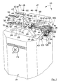
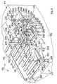
- Fig. 1 Automatic installation, in a continuous line, for treating and colouring the edges and tips of strips perspective view.
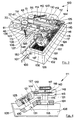
- Fig. 2 Machine for treating and colouring edges of strips perspective.
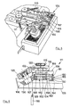
- Fig. 3 The colouring apparatus, perspective.
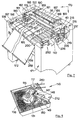
- Fig. 7 Collecting machine for finished strips, with tip colouring apparatus, perspective.
- the installation 10 comprises the machine 20 with ignition switch 14 and with apparatus 100 for processing and colouring the lateral edges and those round the tip of strips in general a drying oven 15 and a strip collecting machine 170 with ignition switch 245 and with an apparatus 215 for colouring the tip.
- the machine 20 with ignition switch 14 has a structure 21 that carries, in a central position on the upper surface, large oblong symmetrical surface plates 22, 23, one opposite the other in relation to the processing direction, and carries at one side the column 24 supporting the control panel 25.
- the surface plates support front 30, 31 and rear 32, 33 pairs of heads to pull and guide strips 34-37, 37', 39, 39'.
- pairs of heads are opposing channels 40 inside which, through windows 44, pulling and guiding rollers 46 project in the front heads, and rollers 47, 48, in the rear heads, with V-shaped grooves 42 opposite each other at the lateral edges 75 of the strip.
- the groove 52 of the rollers 46 in the front heads is knurled while the groove of the rollers 47, 48 in the rear heads is smooth.
- Heads 30, 31 and 32, 33 are replaceable so that differently shaped and sized strips can be treated.
- rollers rotate freely inside holes 41 in the heads, and are made to rotate by short vertical shafts 62 guided by bushes 63 to which they are fixed by dowels 64 (Fig. 2) to facilitate replacement of the rollers.
- a pair of discoid cutters 70 is placed between the front and rear heads described above, followed by a pair of discoid brushes 90.
- Both the cutters 70 and the brushes 90 are rotated by short vertical shafts pulled by a chain worked by an electric motor (not shown).
- Shape and diameter of the cutters are chosen according to requirements.
- the cutters trim the edges 75 of the strip while the brushes 90 prepare them for colouring.
- the surface plates 22, 23 can move like slides, one in relation to another, approaching or moving away from the machine's processing axis; this is done by the flywheel 79 so that distance between the heads 30, 31 and 32, 33 can be varied, adapting groove spacing in the opposing front and rear rollers to the width of the strip in the machine.
- a structure 82 that supports a cutter 85, moved by an electric motor (not shown), worked by the switch 86, for processing the tip 38 of strips like 34.
- the curved chute 13 in line with the processing direction of the machine, facilitates insertion of strips in the opposing channels 40 in the heads 30 and 31.
- Material removed by the cutters and brushes is drawn up by an apparatus (not shown) connected to the suction mouths 26 at the end of the two pairs of channels 27, 28 placed symmetically crosswise in relation to the working axis of the machine, corresponding respectively to the positions of the cutters and brushes.
- This apparatus 100 for colouring the edges of strips.
- This apparatus 100 consists of a boxshaped structure 102, with spacer 101, on which is the vat 105 of colour 106 whose vertical position can be adjusted by an outside lever 103.
- the upper part of said apparatus 100 is composed of two groups 110 111, substantially the same, on either side of the machine's working axis.
- Said groups comprise the plates 112, 113 freely turning round pins 114 held to the above rear heads 32, 33.
- Pulleys 117 with groove 119 are mounted on these pins 116.
- the last pulling and guiding rollers 48 on the rear heads 32, 33 extend upwards to support the pulley 61 in which is a groove 65 that lies on the same plane as the groove 119 of the pulley 117.
- the colouring rollers 115 therefore rotate, by means of a continuous band 120 the same speed as the last pulling and guiding rollers 48.
- a lowered seat 128 is placed to support small plates 125 by means of a pin 127.
- Said small plates 125 are inclined in relation to plates 112, 113 at an angle substantially corresponding to the taper of tapered roller 131 fixed to the pin 122 freely turning, on bearings 121, below said small plate 125.
- the tapered surface 130 of the roller 131 can therefore match with the colouring roller 115 along a substantially vertical line of contact.
- the colouring roller is a groove 124 matching with the edges of strips, like 36, to be coloured.
- Adherence between the tapered roller 131 and the colouring roller 115 is assured by an elastic ring 143 hooked to the heads 144, 145 respectively fixed to the small plate 125 and to the plates 112, 113.
- the amount of colour transferred is adjusted by means of a brush 147 on the end of a small elastic plate 148 supported by a bloch 149 fixed to the underneath of plates 112, 113.
- a threaded knob 150 adjusts pressure on the small plate 148 and therefore that of the brush 147 against the colouring roller 115.
- Said plates 112, 113 are pressed towards each other so that the colouring rollers 115 are kept pressed against the edges 75 of the strip by means of a short arm 133, fixed at the front ends of said plates, onto which a knob 135 with threaded shank is screwed, to this being anchored a traction spring 136 that hooks onto the pin 137 fixed to the surface plates 22 and 23, said spring being locked by the screw 138.
- Figures 5 and 6 illustrate a group 155 for colouring the edges at the sides and tip of strips.
- Said group is substantially the same as device 100 already described, but with the addition to groups 110 and 111, of arms 156 and 157 mounted to rotate freely on the pins 116 of colouring rollers 115.
- Said arms present a bracket 165 inside which is a small colouring roller 160 used for colouring strip tips, said small roller being rotated by bands 162 that connect the groove 161 in said roller with the groove 168 of a pulley 163 between the colouring rollers 115 and said arms 156, 157.
- the tapered roller 131 of the colouring device 100 described above is replaced by a higher roller 167 so that, as seen in Figure 6, colour is deposited both on the colouring roller 115 and on band 162 that allows the absorbed colour 106 to slide into the lower groove 164 of the small colouring roller 160 underneath, so colouring the tip 38 of the strip.
- the small rollers 160 of arms 156 and 157 are kept constantly in contact with the edges of the strip especially at the tip due to the counterweight 158 placed at the end of the rod 159 which, passing over a transmission 152, becomes fixed to the hook 166 mounted on the arms 156, 157.
- This machine consists of a structure 171 containing the electric and pneumatic parts, with a lower cross bar 256 and feet 172.
- the strip On leaving the oven 15, the strip is carried onto the continuous band 175 supported by an end roller like 182 (see figure 7).
- Roller 182 is made to rotate by the continuous band 180 and pulleys 181 and 179 respectively placed on the shaft of roller 182 and on the short shaft of the ratiomotor 178.
- the tip 43 of the strip 36 works a microswitch 185 that operates the pushing devices 186, supported by the bar 187, moved across the strip as far as required by a pair of racks 188 guided by a tube 189 and pulled by gear wheels 190 fixed to the shaft 191 moved by the electric motor 192.
- the strip rests on the continuous bands 195 stretched between the shaft 200 and an opposite transmission shaft placed inside the machine behind the wall 201.
- Shaft 200 is rotated by means of a rack 197 fixed to the piston of a small cylinder 196 that meshes with a gear wheel 198 fixed to said shaft 200. Movement of the bands causes the strips to accumulate in a chute 258. Device 215 proceeds to colour the strip tip before it moves to the chute. During colouring, the presser 205, composed of the cylinder 206, piston 207 and end plate 208, holds the strip in position for colouring the tip 43.
- the colouring device 215, substantially similar to device 100 described above, is mounted on the C-shaped bracket 225 fixed to the inner wall 173 of the structure 171.
- Said bracket 225 supports two freely sliding bars 228 fixed to the head 219 moved by a piston 227 in the cylinder 226 mounted on said bracket.
- Said head supports a vertical shaft 218 around which the angular flat horizontal body, formed by the plate 217, can freely rotate.
- a torsion spring 220 are respectively fixed on the plate 217 and on the clamp 221.
- the clamp 221 is locked by means of the knob 222.
- Parts of the actual colouring unit 215 are substantially the same as those of device 100 already described as can also be seen in Figures 2-4 .
- the plate 212 is fixed to the angular body 217 by a screw 230.
- the colouring roller 115 however is rotated by a ratiomotor mounted on the lower surface of the plate 217.
- the shaft 241 of said ratiomotor 240 passes through said body 217 and has at its end a pulley 242 which, with the band 243 and pulley 117, transmits rotation to the colouring roller 115.
- Figure 9 shows the adjustable brush 147 already described, fixed to the small plate 148 with pressure regulated by the threaded knob 150 supported by the block 149 fixed to the plate 212.
- Simultaneously longitudinal translation determines a rotating movement of the whole colouring unit round the shaft 218 due to the presence of a cam 235 that acts by means of the wheel 236 rotating in the arm 237 fixed by a short column 238 to the plate 217 and due to the simultaneous effect on the tip 43 of the strip 36.
- the cam 235 serves to prevent too much pressure being exerted by the colouring roller 115 on the tip of the strip.
- a cylinder 210 with piston 211 acts by raising the tip 213 to allow translation of the colouring unit 215.
- This unit comprises two fans 251 worked by motors 252 and, above them an electric resistance 253.
- the bands move forward the strips with coloured edges and tips which then pile up on the collecting chute 258.
- the surface 130 coloured rollers 115, 160 and of the tapered rollers 131, 167, in contact with the paint, are coated with diamond powder.
- This coating ensures perfect absorption of colour which is transferred by the tapered rollers 131 and 167, that dip into the vat, and by the colouring rollers 115, 160 and is deposited onto the edges and tips of the strips.
Landscapes
- Engineering & Computer Science (AREA)
- Mechanical Engineering (AREA)
- Chemical & Material Sciences (AREA)
- Organic Chemistry (AREA)
- Manufacturing & Machinery (AREA)
- Treatment Of Fiber Materials (AREA)
- Spectrometry And Color Measurement (AREA)
- Photographic Processing Devices Using Wet Methods (AREA)
Claims (18)
- Installation (10) automatique destinée au traitement de ceintures ou bandes (34-37, 37', 39, 39') le plus souvent en peau, cuir ou matériaux synthétiques
caractérisée par le fait que l'installation comprend une ligne de travail continue, tous ou une partie et dans différentes combinaisons, de moyens (46-48) destinés à l'entraínement et au guidage desdites bandes (34-37, 37', 39, 39') le long de la ligne de travail, agissant comme une côte sur les bords latéraux (75) des bandes susdites, de moyens (20) destinés au traitement des bords latéraux (75) et de la pointe (38, 43, 212, 254) desdites bandes, comprenant des dispositifs (70) de fraisage, de moyens (90) destinés au brossage, de moyens (110, 111; 156, 157) destinés à la coloration, constitués par un rouleau conique (131, 167) ayant un axe incliné, dont la partie inférieure plonge dans un bac (105) à couleur (106) qui est transféré à un rouleau colorieur (115, 160) qui est enfin en contact avec les bords (75) ou la pointe (38, 43, 212, 254) des bandes susdites (34-37, 37', 39, 39'), de moyens (15) destinés au séchage et de moyens (170) destinés à la collecte du produit fini (39'). - Installation (10) comme dans la revendication 1),
caractérisée par le fait que les moyens d'entraínement et guidage des bandes (34-37, 37', 39, 39') sont des rouleaux (46-48) facilement interchangeables pour pouvoir traiter des bandes de toute dimension et tout matériel et ayant des bords (75) d'une forme quelconque, de même que pour pouvoir obtenir les différents effets désirés. - Installation (10) comme dans la revendication 1),
caractérisée par le fait que les moyens d'entraínement et guidage sont des séries de couples de rouleaux motorisés (46-48), dont les éléments sont positionnés de part et d'autre de la ligne de travail et présentent une cannelure (42) circonférentielle fondamentalement en « V », en vue de l'introduction des bords (75) des bandes (34-37, 37', 39, 39'), fondamentalement en « V ». - Installation (10) comme dans la revendication 3),
caractérisée par le fait que chaque couple de rouleaux motorisés est positionné, par libre rotation, sur des couples de têtes, avant (30, 31) et arrières (32, 33) par rapport à l'avancement des bandes opposées (34-39) de part et d'autre de la ligne de travail, interchangeables, supportés par de grosses plaques (22, 23), ces dernières supportées par le plan supérieur (29) de moyens (20) destinés au traitement des bords (75) latéraux et de la pointe des bandes (34-37, 37', 39, 39'), lesdites grosses plaques (22, 23) coulissant librement vers et depuis la ligne de travail, dans un sens ou dans l'autre, sous la commande d'un cinétisme commandé par une manivelle (79) ou par d'autres moyens, permettant d'établir, à discrétion, la distance réciproque entre les éléments correspondants des séries de couples de rouleaux (46-48) d'entraínement et guidage, afin de l'adapter à la largeur et au type de la bande (34-37, 37', 39, 39') à travailler et à obtenir. - Installation (10) comme dans les revendications 1) et 4),
caractérisée par le fait que les dispositifs de fraisage et de brossage sont des couples de fraises (70) et de brosses (90) discoïdales situées sur le plan (29) des moyens (20), dans une position alignée de part et d'autre de la ligne de travail, et placées entre les rouleaux (46-48) d'entraínement et de guidage des bandes (34-37, 37', 39, 39') sur les couples de têtes avant (30, 31) et arrières (32, 33). - Installation (10) comme dans les revendications 1) et 4),
caractérisée par le fait que les différents couples de rouleaux (46) dans les têtes avant (30, 31) présentent des cannelures circonférentielles (52) les autres sont circonférentielles lisses. - Installation (10) comme dans la revendication 1),
caractérisée par le fait que les moyens destinés à la coloration (110, 111) sont des moyens pour la coloration des bords latéraux (75) comprenant une plaque oblongue (112, 113) qui, à une extrémité, accueille, moyennant un roulement à billes (121), un petit arbre (116) solidaire dans sa partie supérieure à une poulie (117) et, au dessous de la plaque (112, 113), à un rouleau colorieur (115) ayant une cannelure (124) circonférentielle destinée à être placée en ligne et en contact avec le bord (75) des ceintures (34-37, 37', 39, 39'), l'extrémité d'une plaquette (125) étant positionnée dans un siège sur l'extrémité latérale arrière externe de chaque plaque (112, 113) et tournant librement autour d'un pivot (127) de raccordement qui accueille à l'extrémité libre, moyennant un roulement (121), un petit arbre (122) d'un rouleau conique (131), ladite plaquette (125) ayant un angle d'inclinaison, par rapport à la plaque (112, 113), fondamentalement égal à la conicité dudit rouleau conique (131), qui met en contact, selon une ligne verticale, sa surface conique avec le rouleau colorieur (115), un bac (105) à couleur (106) étant positionné au niveau dudit rouleau colorieur (115), dans lequel l'extrémité la plus basse du rouleau conique (131) va pêcher, par conséquent la couleur (106) prélevée de ce dernier est transférée par contact au rouleau colorieur (115), l'adhérence entre le rouleau conique (131) et le rouleau colorieur (115) étant assurée par une bague élastique (143) ou un autre moyen similaire, supportée par deux pivots (144, 145) respectivement fixés sur la plaque (112, 113) et sur un côté de ladite plaquette (125). - Installation (10) comme dans la revendication 7),
caractérisée par le fait que les moyens (110, 111) de coloration comprennent un petit bras (156, 157) appliqué à l'arbre (116) de la poulie (117) entre la plaque (112, 113) et le rouleau colorieur (115), moyennant l'introduction dudit arbre dans un trou passant dudit bras (156, 157), une étagère (156) étant prévue à l'extrémité de ce dernier, orientée vers le bas, pour supporter par rotation libre un rouleau oblong (160) comprenant à son extrémité supérieure une cannelure (161) au même niveau qu'une poulie (163) installée entre ledit bras (156, 157) et le rouleau colorieur (115) et solidaire à l'arbre susdit (116), une petite courroie (162) continue étant prévue entre ladite cannelure (161) du rouleau (160) et cette dernière poulie (163), une cannelure (164) étant prévue à l'extrémité inférieure dudit rouleau (160), fondamentalement au niveau de la cannelure (124) du rouleau colorieur (115), ledit rouleau (160) étant gardé appuyé contre la ceinture qui avance le long de la ligne de travail par un moyen de pression; constitué par une cordelette (159) munie d'un contrepoids (158) à l'extrémité, appliquée à un crochet (166) après un renvoi (152) sur le petit bras (156, 157) à une certaine distance de son centre de rotation, le rouleau conique (167) ayant une hauteur apte à contacter soit le rouleau colorieur (115) que la poulie (163) située au-dessus dudit rouleau colorieur (115), entraínant, par effet du prélèvement de la couleur (106) du bac (105) par le rouleau conique (167), le transfert de ladite couleur (106) soit à la cannelure (124) du rouleau colorieur (115), soit à la petite courroie (162) appliquée à la poulie (163) située au-dessus dudit rouleau colorieur (115) et donc le transfert de la couleur (106) par ladite courroie (162), par gravité, à la cannelure (164) inférieure du rouleau colorieur (160), le contrepoids (158) entraínant par conséquent une poussée tendant à faire entrer en contact le rouleau colorieur (160) et la pointe (38) de la ceinture (34-46) qui avance, en permettant ainsi la coloration automatique de ladite pointe (38). - Installation (10) comme dans la revendication 1),
caractérisée par le fait que les moyens de collecte des ceintures (39') finies sont constitués par une ramasseuse (170) comprenant un ruban (175) horizontal continu aligné à la ligne d'avancement des ceintures (34-39) et au moins un couple de dispositifs de poussée (186) transversaux de la ceinture (34-39) qui arrive sur ledit ruban (175) continu, commandés, à travers un cinétisme, par un moteur électrique (178) actionné par la fermeture d'un circuit électrique par un microinterrupteur (185), quand ce dernier est touché par la pointe (43) de la ceinture (36, 39) qui avance, lesdits dispositifs de poussée (186) entraínant le transfert de la ceinture (34-37, 37', 39, 39'), du ruban (175) continu sur une série de petites courroies parallèles (195), continues et tendues entre deux arbres opposés (200), situés sous ledit ruban continu (175) et transversalement à ce dernier, une glissière (258) étant prévue à l'extrémité libre de la série susdite de courroies continues parallèles (195), délimitée par un bord d'extrémité d'où, moyennant la translation des séries de courroies (195), chaque bande (34-39) est transférée au fur et à mesure du ruban continu (175) à la glissière susdite (258), en constituant progressivement un empilage des ceintures (34-37, 37', 39, 39') sur le bord susdit. - Installation (10) comme dans la revendication 9),
caractérisée par le fait que le cinétisme qui commande les dispositifs de poussée (186) comprend un couple de crémaillères (188) transversales au ruban continu (175) sur lequel agissent des pignons (190) supportés par un arbre (191) à l'extrémité duquel le moteur électrique (192) est installé, une barre (187) rainurée étant appliquée à l'extrémité des crémaillères (188) au niveau du ruban continu (175), dans rainure de laquelle sont fixés les dispsitifs de poussée (186) qui peuvent être donc placés dans une position optimale le long de ladite barre (187), en fonction de la longueur de la ceinture (34-37, 37', 39, 39') en cours d'usinage. - Installation (10) comme dans la revendication 7),
caractérisée par le fait que les moyens (110, 111) de coloration des bords (75) des ceintures sont appliqués deux par deux sur la partie arrière du plan supérieur (29) des moyens (20) de traitement des bords latéraux (75) et de la pointe, les plaques oblongues (112, 113) étant appliquées au niveau de leur paroi avant et moyennant des pivots (114) verticaux à la partie arrière des têtes (32, 33) arrières qui supportent les rouleaux (47, 48) de traction et guidage, le dernier couple (48) desdits rouleaux étant prolongé vers le haut en donnant lieu à des corps cylindriques avec une poulie (61) terminale de tête raccordée moyennant une courroie continue (120) à la poulie (117) solidaire au rouleau colorieur (115), lesdites plaques (112, 113) étant poussées l'une contre l'autre par effet d'un bras (133) situé à leur extrémité inférieure qui supporte une vis (135) sur la tige de laquelle est fixé un ressort hélicoïdal (136) raccordé, à l'autre extrémité, à un moyen d'accrochage (137) situé sur le plan (22, 23) des moyens (20), permettant ainsi de régler la tension du ressort (136) en faisant tourner la vis (135), pour assurer le contact continu des rouleaux colorieurs (115) des deux plaques (112, 113) à la fois, contre les bords 75 des ceintures (34-37, 37', 39, 39') qui avancent et donc la coloration desdits bords (75). - Installation (10) comme dans la revendication 8),
caractérisée par le fait que les moyens (110, 111-156, 157) de coloration sont appliqués deux par deux sur la partie arrière du plan supérieur (29) des moyens (20), les plaques oblongues (112, 113) étant appliquées par rotation libre sur les pivots verticaux (114), à l'arrière des têtes (32, 33) arrières qui supportent les rouleaux (47, 48) de traction et guidage, le dernier couple desdits rouleaux (48) étant prolongé vers le haut pour donner lieu à des corps cylindriques avec une poulie (61) terminale de tête raccordés à l'aide d'une courroie continue (120) à la poulie (117) solidaire au rouleau colorieur (115), lesdites plaques (112, 113) étant poussées l'une contre l'autre par effet d'un bras (133) situé à leur extrémité inférieure qui supporte une vis (135) sur la tige de laquelle est fixé un ressort hélicoïdal (136) raccordé, à l'autre extrémité, à un moyen d'accrochage (137) situé sur le plan (22, 23) de la machine (20), permettant ainsi, par la rotation de la vis (135), de régler la tension du ressort (136) pour assurer le contact continu des rouleaux colorieurs (115) et des petits rouleaux colorieurs (160), supportés par les bras (156, 157) appliqués à l'arbre (116) des rouleaux colorieurs (115) des deux plaques (112, 113) à la fois, contre la ceinture (34-36) qui avance et donc la coloration de ses bords (75) latéraux quant à l'action des rouleaux colorieurs (115) et la coloration des bords de sa pointe (38) quant à l'action des petits rouleaux colorieurs (160). - Installation (10) comme dans les revendications 9 et 10),
caractérisée par le fait les moyens de coloration de la pointe (43) sont constitués par un appareillage prévu à l'extrémité arrière de la ramasseuse (170), comprenant un groupe colorieur (215) formé par un chariot (219, 224, 228) glissant librement, transversalement à la ligne d'avancement des ceintures (34-39), sur des supports appropriés (225) solidaires à la ramasseuse (170), une petite colonne verticale (218) étant appliquée au chariot susdit (219, 224, 228) pour supporter, par rotation libre, une grosse plaque horizontale (217) qui, à son extrémité libre, présente le dispositif (110) de coloration, la poulie (117) supérieure du rouleau colorieur (115) étant raccordée par une courroie (243) à un motoréducteur (240) électrique vertical fixé à la surface inférieure de la grosse plaque (217), le bac à couleur (106) étant situé sous le rouleau conique (131), la grosse plaque horizontale (217) étant soumise à l'action d'un ressort hélicoïdal (220) introduit autour de la petite colonne verticale (218) dont les extrémités sont fixées respectivement une à la grosse plaque (217) et l'autre à étau (221) pouvant être bloqué sur cette même colonne (218) après une rotation apte à précharger le ressort (220) de la quantité optimale, un moyen de traction du chariot étant prévu, constitué par le piston (227) d'un cylindre horizontal (226), un presseur (205) étant installé à proximité du ruban continu (175) de la ramasseuse (170), dont un petit pied (208) est situé à proximité du ruban continu (175) de la ramasseuse (170) et gouverné par un cylindre fluidique (206-207), vertical, presseur (205) qui, dès qu'une ceinture (37) passe du ruban continu aux courroies transversales, bloque ladite ceinture (37) alors que le mouvement d'une série de courroies (195) parallèles s'arrête simultanément, la position initiale du rouleau colorieur (115) arrivant presque au niveau d'un côté de la pointe (43) de la ceinture (37) bloquée, par conséquent en entraínant la mise en marche du piston (227) du cylindre (226) sur le chariot (219, 224, 228), le rouleau colorieur (115) est obligé de suivre le contour de la pointe (43), aidé par l'action du ressort hélicoïdal (220) enroulé autour de la colonne (218) sur laquelle peut tourner, guidée par l'expansion inférieure (216) qui lui est solidaire, la grosse plaque horizontale (217) qui supporte le dispositif de coloration (110), d'où l'obtention de la coloration de ladite pointe (43) par effet du mouvement de translation du chariot (219, 224, 228) et du mouvement de rotation du groupe colorieur (215) autour de la colonne (218). - Installation (10) comme dans la revendication 13),
caractérisée par le fait que sur la grosse plaque (217) qui supporte le groupe colorieur (215) est prévue une étagère (238) ayant un support (237) muni d'une roue (236) devant coïncider parfaitement avec une came (235) fondamentalement en arc de cercle, située sur une paroi opposée à ladite roue (236), solidaire à la structure (171) de la ramasseuse (170), les dimensions et les positions de la roue (236) et de la came (235) étant telles que pendant la course du groupe colorieur (215) dans les deux sens lors de la coloration, la roue (236) parcourt la came (235) en créant une trajectoire du groupe colorieur (215) correspondant au profil de la came (235), l'action de ladite came étant concomitante au déplacement du rouleau colorieur (115) sur la pointe (43) de la ceinture (37). - Installation (10) comme dans les revendications 9, 13 et 14),
caractérisée par le fait que les pointes (43, 254) des ceintures (34-39) soumises à la coloration, par effet de l'action de la série de courroies (195) continues parallèles, se meuvent par translation après ladite coloration vers la glissière (258), en passant sous un jet d'air chaud généré, à travers un orifice (257) d'un plan situé sous lesdites pointes (43, 254), par des rotors de ventilation (251) chauffés par une résistance électrique (253), et guidé, ledit jet, sur lesdites pointes (254) par un écran (255) courbé qui, partant d'un bord de l'orifice (257) s'élève et se courbe vers les pointes qui se meuvent par translation (43, 254). - Installation (10) comme dans les revendications 7 et 8),
caractérisée par le fait que la surface des cannelures (124, 164) des rouleaux colorieurs (115) et des petits rouleaux colorieurs (160) qui entrent en contact avec les bords de la ceinture (34-37, 37', 39, 39') et la surface des rouleaux coniques (131, 167) qui transfèrent la couleur du bac à couleur (106) auxdits rouleaux colorieurs (115, 160) sont revêtues de poudre de diamant (130) pour assurer l'absorption et le transfert régulier de la couleur (106) du bac (105) aux bords de la ceinture (34-37, 37', 39, 39'). - Installation (10) comme dans les revendications 7 et 8),
caractérisée par le fait que la quantité de couleur distribuée sur les rouleaux colorieurs (115) est réglée par un pinceau (147) situé à l'extrémité d'une bande métallique élastique (148), qui pèse sur la cannelure (124) desdits rouleaux (115) selon une pression réglable à l'aide d'une poignée (150) ayant un maneton fileté dont la pointe (151) agit sur ladite bande (148). - Installation (10) comme dans les revendications 1, 5 et 9),
caractérisée par le fait que les moyens de séchage sont constitués par un four tunnel (15) et à passage continu, pouvant être inséré en ligne continue entre les moyens (20) et la ramasseuse (170).
Applications Claiming Priority (3)
| Application Number | Priority Date | Filing Date | Title |
|---|---|---|---|
| IT98MI000979 IT1303062B1 (it) | 1998-05-06 | 1998-05-06 | Impianto automatico in linea continua per la lavorazione e lacolorazione dei bordi laterali e della punta delle cinture e di |
| ITMI980979 | 1998-05-06 | ||
| PCT/IT1998/000142 WO1999057327A1 (fr) | 1998-05-06 | 1998-05-28 | Installation automatique en continu pour le traitement et la coloration des bords et des languettes de lanieres en cuir, en matiere synthetique et autres |
Publications (2)
| Publication Number | Publication Date |
|---|---|
| EP1075552A1 EP1075552A1 (fr) | 2001-02-14 |
| EP1075552B1 true EP1075552B1 (fr) | 2002-03-20 |
Family
ID=11379962
Family Applications (1)
| Application Number | Title | Priority Date | Filing Date |
|---|---|---|---|
| EP98929620A Expired - Lifetime EP1075552B1 (fr) | 1998-05-06 | 1998-05-28 | Installation automatique en continu pour le traitement et la coloration des bords et des languettes de lanières en cuir ou matière synthétique |
Country Status (4)
| Country | Link |
|---|---|
| EP (1) | EP1075552B1 (fr) |
| DE (1) | DE69804359D1 (fr) |
| IT (1) | IT1303062B1 (fr) |
| WO (1) | WO1999057327A1 (fr) |
Families Citing this family (11)
| Publication number | Priority date | Publication date | Assignee | Title |
|---|---|---|---|---|
| ITMI20030881A1 (it) * | 2003-04-30 | 2004-11-01 | Galli S P A | Metodo ed apparecchiatura per la finitura superficiale di bordi di manufatti in pelle, cuoio e simili materiali |
| ITMI20081897A1 (it) * | 2008-10-27 | 2010-04-28 | Galli S P A | Macchina per la realizzazione di prodotti in strisce |
| IT1392144B1 (it) * | 2008-10-27 | 2012-02-22 | Galli S P A | Dispositivo per la colorazione di prodotti in strisce quali cinture e simili e relativo procedimento di colorazione |
| ITVE20090060A1 (it) * | 2009-10-12 | 2011-04-13 | Omac Srl | Procedimento di colorazione dei bordi di articoli in pelle e macchina tingibordo.- |
| ES2681235T3 (es) * | 2015-02-19 | 2018-09-12 | Galli S.P.A. | Dispositivo y método para la deposición de artículos de cuero, tales como cinturones o similares |
| ITUB20160932A1 (it) * | 2016-02-22 | 2017-08-22 | Galli S P A | Macchina per la colorazione di articoli vari in pelle e in similpelle |
| ITUB20160911A1 (it) * | 2016-02-22 | 2017-08-22 | Galli S P A | Macchina per la colorazione di articoli vari in pelle e in similpelle |
| ITUB20160941A1 (it) * | 2016-02-22 | 2017-08-22 | Galli S P A | Macchina per la colorazione di articoli vari in pelle e in similpelle |
| ITUB20160978A1 (it) * | 2016-02-23 | 2017-08-23 | Galli S P A | Forno di asciugatura per articoli di pelletteria o simili |
| IT201700019379A1 (it) * | 2017-02-21 | 2018-08-21 | Omac Srl | Macchina per il trattamento in verticale di manufatti di pelle o simili materiali. |
| IT202000003245A1 (it) * | 2020-02-18 | 2021-08-18 | Omac Srl | Macchina per la colorazione di manufatti |
Family Cites Families (2)
| Publication number | Priority date | Publication date | Assignee | Title |
|---|---|---|---|---|
| US1451686A (en) * | 1919-01-28 | 1923-04-17 | Czaran Otto | Apparatus for making belting |
| GB2029738A (en) * | 1978-08-03 | 1980-03-26 | Henderson Diamond Tool Co Ltd | Cutting machine |
-
1998
- 1998-05-06 IT IT98MI000979 patent/IT1303062B1/it active IP Right Grant
- 1998-05-28 EP EP98929620A patent/EP1075552B1/fr not_active Expired - Lifetime
- 1998-05-28 DE DE69804359T patent/DE69804359D1/de not_active Expired - Lifetime
- 1998-05-28 WO PCT/IT1998/000142 patent/WO1999057327A1/fr not_active Ceased
Also Published As
| Publication number | Publication date |
|---|---|
| IT1303062B1 (it) | 2000-10-23 |
| DE69804359D1 (de) | 2002-04-25 |
| WO1999057327A1 (fr) | 1999-11-11 |
| ITMI980979A1 (it) | 1999-11-06 |
| EP1075552A1 (fr) | 2001-02-14 |
Similar Documents
| Publication | Publication Date | Title |
|---|---|---|
| EP1075552B1 (fr) | Installation automatique en continu pour le traitement et la coloration des bords et des languettes de lanières en cuir ou matière synthétique | |
| US3953942A (en) | Apparatus for grinding inner surface of a vehicle tire | |
| EP0341387A2 (fr) | Dispositif pour le glaçage des pièces en argile ou porcelaine et pour supporter ou maintenir les pièces travaillées | |
| US3951057A (en) | Nut blanching apparatus | |
| US4186043A (en) | Method for hemming fabric using a hot melt adhesive | |
| US2690207A (en) | Tire tread cementing machine | |
| US1977704A (en) | Glazing machine | |
| US3826227A (en) | Tinning machine | |
| US6199411B1 (en) | Dyeing range unloader | |
| CN115157052B (zh) | 一种竹凉席加工用竹片拉丝磨边设备及使用方法 | |
| US4286938A (en) | Oval dish former | |
| US1945883A (en) | Tire tread splitting apparatus | |
| NO149290B (no) | Fremgangsmaate og innretning for kontinuerlig fremstilling av isolasjonshylser. | |
| US4368021A (en) | Oval dish forming method and machine | |
| CN208929957U (zh) | 一种用于球棒棒身表面抛光的快速抛光装置 | |
| CN208929954U (zh) | 一种用于球棒棒身表面抛光装置 | |
| US4542634A (en) | Staking machine | |
| US4010515A (en) | Animal skinning apparatus | |
| CN211431478U (zh) | 全自动卧式植毛修毛开花一体机 | |
| US2382089A (en) | Fur wetting apparatus | |
| US1939770A (en) | Pipe forming machine | |
| US4099287A (en) | Cylindrical wound brush | |
| US4590979A (en) | Device for bark-peeling tree trunks or the like | |
| CN219824251U (zh) | 一种牛皮加工用染色装置 | |
| CN214812268U (zh) | 一种绿色spu背胶的人造草坪烘干装置 |
Legal Events
| Date | Code | Title | Description |
|---|---|---|---|
| PUAI | Public reference made under article 153(3) epc to a published international application that has entered the european phase |
Free format text: ORIGINAL CODE: 0009012 |
|
| 17P | Request for examination filed |
Effective date: 20000901 |
|
| AK | Designated contracting states |
Kind code of ref document: A1 Designated state(s): DE ES FR |
|
| GRAG | Despatch of communication of intention to grant |
Free format text: ORIGINAL CODE: EPIDOS AGRA |
|
| RTI1 | Title (correction) |
Free format text: CONTINUOUS AUTOMATIC INSTALLATION FOR PROCESSING AND COLOURING THE EDGES AND TIP OF BELTS OR OTHER STRIPS OF LEATHER OR SYNTHETIC MATERIAL |
|
| GRAG | Despatch of communication of intention to grant |
Free format text: ORIGINAL CODE: EPIDOS AGRA |
|
| GRAH | Despatch of communication of intention to grant a patent |
Free format text: ORIGINAL CODE: EPIDOS IGRA |
|
| 17Q | First examination report despatched |
Effective date: 20010723 |
|
| GRAH | Despatch of communication of intention to grant a patent |
Free format text: ORIGINAL CODE: EPIDOS IGRA |
|
| GRAA | (expected) grant |
Free format text: ORIGINAL CODE: 0009210 |
|
| AK | Designated contracting states |
Kind code of ref document: B1 Designated state(s): DE ES FR |
|
| PG25 | Lapsed in a contracting state [announced via postgrant information from national office to epo] |
Ref country code: FR Free format text: LAPSE BECAUSE OF FAILURE TO SUBMIT A TRANSLATION OF THE DESCRIPTION OR TO PAY THE FEE WITHIN THE PRESCRIBED TIME-LIMIT Effective date: 20020320 |
|
| REF | Corresponds to: |
Ref document number: 69804359 Country of ref document: DE Date of ref document: 20020425 |
|
| PG25 | Lapsed in a contracting state [announced via postgrant information from national office to epo] |
Ref country code: DE Free format text: LAPSE BECAUSE OF FAILURE TO SUBMIT A TRANSLATION OF THE DESCRIPTION OR TO PAY THE FEE WITHIN THE PRESCRIBED TIME-LIMIT Effective date: 20020621 |
|
| PG25 | Lapsed in a contracting state [announced via postgrant information from national office to epo] |
Ref country code: ES Free format text: LAPSE BECAUSE OF FAILURE TO SUBMIT A TRANSLATION OF THE DESCRIPTION OR TO PAY THE FEE WITHIN THE PRESCRIBED TIME-LIMIT Effective date: 20020925 |
|
| EN | Fr: translation not filed | ||
| PLBE | No opposition filed within time limit |
Free format text: ORIGINAL CODE: 0009261 |
|
| STAA | Information on the status of an ep patent application or granted ep patent |
Free format text: STATUS: NO OPPOSITION FILED WITHIN TIME LIMIT |
|
| 26N | No opposition filed |
Effective date: 20021223 |