EP1075552B1 - Vorrichtung zur kontinuierlichen automatischen Verarbeitung und Färbung der Ränder und Spitzen von Gürteln oder anderen Bändern aus Leder oder Kunststoff - Google Patents
Vorrichtung zur kontinuierlichen automatischen Verarbeitung und Färbung der Ränder und Spitzen von Gürteln oder anderen Bändern aus Leder oder Kunststoff Download PDFInfo
- Publication number
- EP1075552B1 EP1075552B1 EP98929620A EP98929620A EP1075552B1 EP 1075552 B1 EP1075552 B1 EP 1075552B1 EP 98929620 A EP98929620 A EP 98929620A EP 98929620 A EP98929620 A EP 98929620A EP 1075552 B1 EP1075552 B1 EP 1075552B1
- Authority
- EP
- European Patent Office
- Prior art keywords
- colouring
- roller
- rollers
- strips
- strip
- Prior art date
- Legal status (The legal status is an assumption and is not a legal conclusion. Google has not performed a legal analysis and makes no representation as to the accuracy of the status listed.)
- Expired - Lifetime
Links
- 238000004040 coloring Methods 0.000 title claims description 152
- 238000009434 installation Methods 0.000 title claims description 28
- 238000012545 processing Methods 0.000 title claims description 23
- 239000010985 leather Substances 0.000 title claims description 5
- 229920002994 synthetic fiber Polymers 0.000 title claims description 3
- 238000012546 transfer Methods 0.000 claims description 9
- 238000001035 drying Methods 0.000 claims description 8
- 239000000463 material Substances 0.000 claims description 6
- 230000001680 brushing effect Effects 0.000 claims description 5
- 238000013519 translation Methods 0.000 claims description 5
- 230000005540 biological transmission Effects 0.000 claims description 4
- 229910003460 diamond Inorganic materials 0.000 claims description 4
- 239000010432 diamond Substances 0.000 claims description 4
- ZZUFCTLCJUWOSV-UHFFFAOYSA-N furosemide Chemical compound C1=C(Cl)C(S(=O)(=O)N)=CC(C(O)=O)=C1NCC1=CC=CO1 ZZUFCTLCJUWOSV-UHFFFAOYSA-N 0.000 claims description 4
- 238000003780 insertion Methods 0.000 claims description 4
- 230000037431 insertion Effects 0.000 claims description 4
- 239000000843 powder Substances 0.000 claims description 4
- 238000010521 absorption reaction Methods 0.000 claims description 3
- 238000000034 method Methods 0.000 claims description 3
- 230000001105 regulatory effect Effects 0.000 claims description 3
- 230000000694 effects Effects 0.000 claims description 2
- 230000005484 gravity Effects 0.000 claims description 2
- 230000036316 preload Effects 0.000 claims description 2
- 230000000284 resting effect Effects 0.000 claims description 2
- 239000011248 coating agent Substances 0.000 description 2
- 238000000576 coating method Methods 0.000 description 2
- 238000003825 pressing Methods 0.000 description 2
- 239000002699 waste material Substances 0.000 description 2
- 230000002301 combined effect Effects 0.000 description 1
- 238000013461 design Methods 0.000 description 1
- 230000006866 deterioration Effects 0.000 description 1
- 230000001788 irregular Effects 0.000 description 1
- 239000003973 paint Substances 0.000 description 1
- 238000009958 sewing Methods 0.000 description 1
- 230000002226 simultaneous effect Effects 0.000 description 1
- 125000006850 spacer group Chemical group 0.000 description 1
Images

Classifications
-
- C—CHEMISTRY; METALLURGY
- C14—SKINS; HIDES; PELTS; LEATHER
- C14B—MECHANICAL TREATMENT OR PROCESSING OF SKINS, HIDES OR LEATHER IN GENERAL; PELT-SHEARING MACHINES; INTESTINE-SPLITTING MACHINES
- C14B17/00—Details of apparatus or machines for manufacturing or treating skins, hides, leather, or furs
- C14B17/06—Work feeding or clamping devices
-
- C—CHEMISTRY; METALLURGY
- C14—SKINS; HIDES; PELTS; LEATHER
- C14B—MECHANICAL TREATMENT OR PROCESSING OF SKINS, HIDES OR LEATHER IN GENERAL; PELT-SHEARING MACHINES; INTESTINE-SPLITTING MACHINES
- C14B11/00—Finishing the edges of leather pieces, e.g. by folding, by burning
-
- C—CHEMISTRY; METALLURGY
- C14—SKINS; HIDES; PELTS; LEATHER
- C14B—MECHANICAL TREATMENT OR PROCESSING OF SKINS, HIDES OR LEATHER IN GENERAL; PELT-SHEARING MACHINES; INTESTINE-SPLITTING MACHINES
- C14B9/00—Making driving belts or other leather belts or strips
Definitions
- the strip In automatic installations for treating belts or other strips of leather or of other materials, especially for cutting and colouring the edges, the strip is laid flat and is carried forward by rollers pressing on either side.
- the belts are cut from a leather disk and, after various processes, are cleaned, shaped to the required cross section, smoothed and hardened under pull from opposing rollers that therefore operate "flat" on the two faces of the belt.
- Subject of the invention is an automatic installation for treating belts and other strip-like pieces of leather or synthetic material.
- this installation comprises all or part and various combinations of means for pulling and guiding the strips along the processing line, operating laterally on the edges of the strips, means for treating the lateral edges and tip of strips compring cutting means, brushing means, colouring means consisting of a tapered roller the axis of which is inclined and the lower end of which is immersed in a vat of colour that becomes transferred to a colouring roller which finally makes contact with the edges or the tip of the strips, means for drying and means for gathering up the finished product.
- the means that pull and guide the strips are pairs of replaceable rollers to treat strips of practically any size and material, with edges of any shape and for obtaining the various desired effects, with a substantially V-shaped groove into which the edges of the strips are fitted.
- the set of rollers is motor-driven and the rollers rotate freely in pairs of heads, at the front and back in relation to the strip forward movement, opposite one another on the working line and replaceable, supported by surface plates which in turn rest on the upper surface of the means for treating the side edges of the strips.
- Said surface plates slide, transversally to the working line, on both sides, operated by a mechanism worked by a handle or other means, so that the reciprocal distance can be decided at will between the corresponding parts of the pairs of pulling and guiding rollers, to suit it to the width and type of strip to be treated and produced.
- the cutting and brushing means are pairs of discoid cutters and brushes placed on the surface of the machine and aligned on either side of the processing line, between the two sets, front and back, of pulling and guiding rollers placed respectively in the pairs of front and back heads.
- the various pairs of rollers in the front heads have circumferential knurled grooves while the pairs of rollers in the rear heads have circumferential smooth grooves.
- the colouring means comprises an oblong plate at one end of which a short shaft, resting on a ball bearing, is fixed above to a pulley and, below the plate, to a colouring roller in which there is a circumferential groove to be aligned and brought in contact with the edge of the strip.
- the end of a small plate is placed in a seat made for it on the outer lateral rear end of each plate, this small plate freely turning round a connecting pin at whose free end a bearing supports the short shaft of a tapered roller.
- the small plate is inclined in relation to the other plate at an angle substantially equal to the taper of said tapered roller which places its tapered surface in contact, according to a vertical line, with the colouring roller.
- At the position occupied by said colouring roller is a small vat of colour into which the lower end of the tapered roller dips, the colour it picks up being then transferred by contact to the colouring roller.
- Adherence between the tapered roller and the colouring roller is ensured by an elastic ring or similar means, supported by two pins fixed respectively to the plate and to one side of the small plate.
- the colouring device comprises a short arm applied to the pulley shaft between the plate and the colouring roller by insertion of said shaft in a hole passing through said arm.
- a downward-facing bracket that, freely rotating, supports a small oblong roller at whose upper end is a groove at the same level as that of a pulley fitted between said arm and the colouring roller and fixed to said shaft.
- a continuous band connects said groove with this latter pulley.
- Said small roller is pressed against the advancing strip along the line of work, by a pressing means consisting of a cord with a counterweight at one end, said cord passing over a transmission and then connecting with the above arm at some distance from its centre of rotation.
- the tapered roller is high enough to contact both the colouring roller and the pulley above said roller.
- the counterweights produce a thrust tending to create contact between the two small colouring rollers of the device, ensuring contact between the lower groove in said pair of small rollers and the tip of the advancing strip thus automatically colouring the tip.
- the means for collecting finished strips consists of a machine comprising a continuous horizontal band, aligned with the advancing line of strips and of at least one pair of transversal thrust means for the strip that reaches said continuous band, operated by a motor-driven mechanism whose motor is turned on when an electric circuit is closed by a microswitch as soon as it is hit by the tip of an advancing strip.
- Said thrust means determines transfer of the strip from the continuous band onto a set of parallel continuous bands stretched between two opposite shafts that lie below said continuous band and across it.
- a chute At the free end of said set of bands is a a chute with flat terminal area so that, by translation of the short bands, each strip is moved from the continuous band to said chute and the strips become piled up on said terminal area.
- the mechanism that controls the thrust means comprises a pair of racks, crosswise to the continuous band, against which pinions press supported by a shaft with an electric motor on its end.
- a grooved bar is mounted at the ends of the racks, at the position of the continuous band, the thrust means taking up a position along the groove in the bar, according to the length of the strip on the working line.
- means is applied to the rear of the upper surface of the means for treating the lateral edges and tip of the strip.
- the oblong plates are mounted, free to rotate, on vertical pins placed on the front of said plates and towards the back of the rear heads that carry the pulling and guiding rollers.
- the last pair of said rollers has an upward extension forming cylindrical bodies with a terminal pulley at the end connected, by a continuous band, to the pulley fixed to the colouring roller.
- Said plates are pressed together by an arm placed at their lower ends at which there is a screw to whose shank a helical spring is fixedly connected at the other end to a hooking means placed on the surface plates of the machine.
- spring tension can be adjusted to ensure continuous contact between the colouring rollers on the pair of plates and the advancing strip whose edges then receive the colour.
- a pair of colouring means is mounted on the rear end of the upper surface of the means for treating the lateral edges and tip of the strip.
- the oblong plates turn freely on vertical pins placed on the front of said plates and on the rear side of the rear heads that carry the pulliny and guiding rollers.
- the last pair of said rollers extend upwards forming cylindrical bodies with a terminal pulley, these cylindrical bodies being joined, by a continuous band to the pulley fixed to the colouring roller.
- Said plates are pressed against each other by an arm at their lower ends that carry a screw on whose shank a helical spring is fixedly connected to the other end by a hooking means on the surface plates of the machine.
- spring tension can be adjusted by turning the screw, ensuring continuous contact by the colouring rollers and the small colouring rollers, supported by arms mounted on the short shaft of the colouring roller on the pair of plates, against the advancing strip so that the colouring rollers colour its edges and the small colouring rollers colour its tip.
- the means for colouring the edges around the tip consist of a device placed at the rear end of the collecting machine, comprising a colouring unit formed of a slide that moves crosswise to the strips forward movement on supports fixed to the machine.
- a vertical column On said slide is a vertical column that supports a large horizontal plate sliding freely round a shaft and supporting, at its opposite end, a colouring device.
- the upper pulley of the colouring roller is connected by a band to a vertical electric motor carried by said slide.
- a means for moving is provided for the slide, said means being a piston of a horizontal cylinder.
- a presser operated by a vertical fluidic cylinder, stops and holds a strip, as soon as it passes from the continuous band to the transversal bands, so causing simultaneous stoppage of said bands.
- the initial position of the colouring roller is at one side of the tip of the strip now stopped, so that by operating the piston in the cylinder on the slide the colouring roller is obliged to move round the tip aided by action of the helical spring on the column supporting the colouring device.
- the tip is thus coloured by the combined effect of movement of the slide and rotation of the colouring unit round the column.
- a bracket on the large plate that supports the colouring unit is a wheel that will match with a substantially arched cam on a wall opposite said wheel fixed to the structure of the machine.
- Size and positions of wheel and cam are such that when a stroke is made by the colouring unit in both directions during colouring, the wheel pursues the cam creating a trajectory for the colouring unit that corresponds to the outline of the cam.
- Action of said cam is concomitant with movement of the colouring roller round the tip of the strip.
- the tips of the strip when coloured pass on towards a chute, passing through a jet of warm air from a hole in a surface below said tips and generated by fans and by an electric resistance, guided onto the tips by a curved screen which rises from one edge of the hole and curves towards the translating tips.
- the surface of the grooves in the colouring rollers and small colouring rollers that make contact with the edges of the strip, and the surface of the tapered rollers that transfer colour from the vat to the colouring rollers, are coated with diamond powder to ensure absorption and uniform transfer of colour from the vat to the edges of the strip.
- the quantity of colour distributed by the colouring rollers is regulated by a brush placed at the end of an elastic plate that weighs on the groove of said rollers at a pressure adjustable by a knob with threaded pin whose tip presses on said small plate.
- Drying means preferably consist of a tunnel oven and continuous band placed in line between the processing and collecting machines.
- the invention offers evident advantages.
- Brushes placed after the cutters prepare the edges for perfect colouring and ensure a good aesthetic result.
- the shape of the colouring rollers with grooves practically aligned with those of the pulling and guiding rollers, and coating of said grooves with diamond powder provides a secure hold and spreads colour evenly. Continuous movement of strips between the pulling and guiding rollers on to the colouring rollers not only ensures a good result but reduces waste, speeds up output and therefore lowers running costs.
- the possibility of whether or not to associate the colouring device for edges only or edges of the tips as well, to the processing machine, or possibility of associating the colouring of the tips to the collecting machine gives flexibility according to the strips to be processed and according to the customer's preferences.
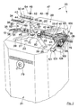
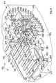
- Fig. 1 Automatic installation, in a continuous line, for treating and colouring the edges and tips of strips perspective view.
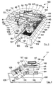
- Fig. 2 Machine for treating and colouring edges of strips perspective.
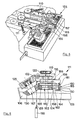
- Fig. 3 The colouring apparatus, perspective.
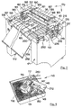
- Fig. 7 Collecting machine for finished strips, with tip colouring apparatus, perspective.
- the installation 10 comprises the machine 20 with ignition switch 14 and with apparatus 100 for processing and colouring the lateral edges and those round the tip of strips in general a drying oven 15 and a strip collecting machine 170 with ignition switch 245 and with an apparatus 215 for colouring the tip.
- the machine 20 with ignition switch 14 has a structure 21 that carries, in a central position on the upper surface, large oblong symmetrical surface plates 22, 23, one opposite the other in relation to the processing direction, and carries at one side the column 24 supporting the control panel 25.
- the surface plates support front 30, 31 and rear 32, 33 pairs of heads to pull and guide strips 34-37, 37', 39, 39'.
- pairs of heads are opposing channels 40 inside which, through windows 44, pulling and guiding rollers 46 project in the front heads, and rollers 47, 48, in the rear heads, with V-shaped grooves 42 opposite each other at the lateral edges 75 of the strip.
- the groove 52 of the rollers 46 in the front heads is knurled while the groove of the rollers 47, 48 in the rear heads is smooth.
- Heads 30, 31 and 32, 33 are replaceable so that differently shaped and sized strips can be treated.
- rollers rotate freely inside holes 41 in the heads, and are made to rotate by short vertical shafts 62 guided by bushes 63 to which they are fixed by dowels 64 (Fig. 2) to facilitate replacement of the rollers.
- a pair of discoid cutters 70 is placed between the front and rear heads described above, followed by a pair of discoid brushes 90.
- Both the cutters 70 and the brushes 90 are rotated by short vertical shafts pulled by a chain worked by an electric motor (not shown).
- Shape and diameter of the cutters are chosen according to requirements.
- the cutters trim the edges 75 of the strip while the brushes 90 prepare them for colouring.
- the surface plates 22, 23 can move like slides, one in relation to another, approaching or moving away from the machine's processing axis; this is done by the flywheel 79 so that distance between the heads 30, 31 and 32, 33 can be varied, adapting groove spacing in the opposing front and rear rollers to the width of the strip in the machine.
- a structure 82 that supports a cutter 85, moved by an electric motor (not shown), worked by the switch 86, for processing the tip 38 of strips like 34.
- the curved chute 13 in line with the processing direction of the machine, facilitates insertion of strips in the opposing channels 40 in the heads 30 and 31.
- Material removed by the cutters and brushes is drawn up by an apparatus (not shown) connected to the suction mouths 26 at the end of the two pairs of channels 27, 28 placed symmetically crosswise in relation to the working axis of the machine, corresponding respectively to the positions of the cutters and brushes.
- This apparatus 100 for colouring the edges of strips.
- This apparatus 100 consists of a boxshaped structure 102, with spacer 101, on which is the vat 105 of colour 106 whose vertical position can be adjusted by an outside lever 103.
- the upper part of said apparatus 100 is composed of two groups 110 111, substantially the same, on either side of the machine's working axis.
- Said groups comprise the plates 112, 113 freely turning round pins 114 held to the above rear heads 32, 33.
- Pulleys 117 with groove 119 are mounted on these pins 116.
- the last pulling and guiding rollers 48 on the rear heads 32, 33 extend upwards to support the pulley 61 in which is a groove 65 that lies on the same plane as the groove 119 of the pulley 117.
- the colouring rollers 115 therefore rotate, by means of a continuous band 120 the same speed as the last pulling and guiding rollers 48.
- a lowered seat 128 is placed to support small plates 125 by means of a pin 127.
- Said small plates 125 are inclined in relation to plates 112, 113 at an angle substantially corresponding to the taper of tapered roller 131 fixed to the pin 122 freely turning, on bearings 121, below said small plate 125.
- the tapered surface 130 of the roller 131 can therefore match with the colouring roller 115 along a substantially vertical line of contact.
- the colouring roller is a groove 124 matching with the edges of strips, like 36, to be coloured.
- Adherence between the tapered roller 131 and the colouring roller 115 is assured by an elastic ring 143 hooked to the heads 144, 145 respectively fixed to the small plate 125 and to the plates 112, 113.
- the amount of colour transferred is adjusted by means of a brush 147 on the end of a small elastic plate 148 supported by a bloch 149 fixed to the underneath of plates 112, 113.
- a threaded knob 150 adjusts pressure on the small plate 148 and therefore that of the brush 147 against the colouring roller 115.
- Said plates 112, 113 are pressed towards each other so that the colouring rollers 115 are kept pressed against the edges 75 of the strip by means of a short arm 133, fixed at the front ends of said plates, onto which a knob 135 with threaded shank is screwed, to this being anchored a traction spring 136 that hooks onto the pin 137 fixed to the surface plates 22 and 23, said spring being locked by the screw 138.
- Figures 5 and 6 illustrate a group 155 for colouring the edges at the sides and tip of strips.
- Said group is substantially the same as device 100 already described, but with the addition to groups 110 and 111, of arms 156 and 157 mounted to rotate freely on the pins 116 of colouring rollers 115.
- Said arms present a bracket 165 inside which is a small colouring roller 160 used for colouring strip tips, said small roller being rotated by bands 162 that connect the groove 161 in said roller with the groove 168 of a pulley 163 between the colouring rollers 115 and said arms 156, 157.
- the tapered roller 131 of the colouring device 100 described above is replaced by a higher roller 167 so that, as seen in Figure 6, colour is deposited both on the colouring roller 115 and on band 162 that allows the absorbed colour 106 to slide into the lower groove 164 of the small colouring roller 160 underneath, so colouring the tip 38 of the strip.
- the small rollers 160 of arms 156 and 157 are kept constantly in contact with the edges of the strip especially at the tip due to the counterweight 158 placed at the end of the rod 159 which, passing over a transmission 152, becomes fixed to the hook 166 mounted on the arms 156, 157.
- This machine consists of a structure 171 containing the electric and pneumatic parts, with a lower cross bar 256 and feet 172.
- the strip On leaving the oven 15, the strip is carried onto the continuous band 175 supported by an end roller like 182 (see figure 7).
- Roller 182 is made to rotate by the continuous band 180 and pulleys 181 and 179 respectively placed on the shaft of roller 182 and on the short shaft of the ratiomotor 178.
- the tip 43 of the strip 36 works a microswitch 185 that operates the pushing devices 186, supported by the bar 187, moved across the strip as far as required by a pair of racks 188 guided by a tube 189 and pulled by gear wheels 190 fixed to the shaft 191 moved by the electric motor 192.
- the strip rests on the continuous bands 195 stretched between the shaft 200 and an opposite transmission shaft placed inside the machine behind the wall 201.
- Shaft 200 is rotated by means of a rack 197 fixed to the piston of a small cylinder 196 that meshes with a gear wheel 198 fixed to said shaft 200. Movement of the bands causes the strips to accumulate in a chute 258. Device 215 proceeds to colour the strip tip before it moves to the chute. During colouring, the presser 205, composed of the cylinder 206, piston 207 and end plate 208, holds the strip in position for colouring the tip 43.
- the colouring device 215, substantially similar to device 100 described above, is mounted on the C-shaped bracket 225 fixed to the inner wall 173 of the structure 171.
- Said bracket 225 supports two freely sliding bars 228 fixed to the head 219 moved by a piston 227 in the cylinder 226 mounted on said bracket.
- Said head supports a vertical shaft 218 around which the angular flat horizontal body, formed by the plate 217, can freely rotate.
- a torsion spring 220 are respectively fixed on the plate 217 and on the clamp 221.
- the clamp 221 is locked by means of the knob 222.
- Parts of the actual colouring unit 215 are substantially the same as those of device 100 already described as can also be seen in Figures 2-4 .
- the plate 212 is fixed to the angular body 217 by a screw 230.
- the colouring roller 115 however is rotated by a ratiomotor mounted on the lower surface of the plate 217.
- the shaft 241 of said ratiomotor 240 passes through said body 217 and has at its end a pulley 242 which, with the band 243 and pulley 117, transmits rotation to the colouring roller 115.
- Figure 9 shows the adjustable brush 147 already described, fixed to the small plate 148 with pressure regulated by the threaded knob 150 supported by the block 149 fixed to the plate 212.
- Simultaneously longitudinal translation determines a rotating movement of the whole colouring unit round the shaft 218 due to the presence of a cam 235 that acts by means of the wheel 236 rotating in the arm 237 fixed by a short column 238 to the plate 217 and due to the simultaneous effect on the tip 43 of the strip 36.
- the cam 235 serves to prevent too much pressure being exerted by the colouring roller 115 on the tip of the strip.
- a cylinder 210 with piston 211 acts by raising the tip 213 to allow translation of the colouring unit 215.
- This unit comprises two fans 251 worked by motors 252 and, above them an electric resistance 253.
- the bands move forward the strips with coloured edges and tips which then pile up on the collecting chute 258.
- the surface 130 coloured rollers 115, 160 and of the tapered rollers 131, 167, in contact with the paint, are coated with diamond powder.
- This coating ensures perfect absorption of colour which is transferred by the tapered rollers 131 and 167, that dip into the vat, and by the colouring rollers 115, 160 and is deposited onto the edges and tips of the strips.
Landscapes
- Engineering & Computer Science (AREA)
- Mechanical Engineering (AREA)
- Chemical & Material Sciences (AREA)
- Organic Chemistry (AREA)
- Manufacturing & Machinery (AREA)
- Treatment Of Fiber Materials (AREA)
- Spectrometry And Color Measurement (AREA)
- Photographic Processing Devices Using Wet Methods (AREA)
Claims (18)
- Automatische Anlage (10) zur Behandlung von Gürtel oder Streifen (34-37, 37', 39, 39') im allgemeinen aus Leder oder synthetischem Material,
dadurch gekennzeichnet, daß die Anlage in der kontinuierlichen Arbeitslinie alle oder Teil von folgenden Elementen und in verschiedenen Kombinationen einschließt: Zieh- und Führungsmittel (46-48) der genannten Streifen (34-37, 37', 39, 39') längs der Arbeitslinie, Flankenkomponenten an den Seitenrändern (75) der genannten Streifen, Mittel (20) zur Behandlung der Seitenränder (75) und der Spitze (38, 43, 212, 254) der genannten Streifen, die Fräsmittel (79), Bürstmittel (90), Färbungsmittel (110, 111; 156, 157) einschließen, die aus einer kegelförmigen Rolle (131, 167) mit schräggestellter Achse, dessen unterer Teil in die Farbwanne (105) mit der Farbe (106) eintaucht, die auf die Färbungsrolle (115, 160) übertragen wird, die schließlich in Kontakt mit den Rändern (75) oder der Spitze (38, 43, 215, 254) der Streifen (34-37, 37', 39, 39') kommr, Mittel (15) für die Trocknung und Mittel (170) zur Sammlung des Endproduktes (39'). - Anlage (10) wie nach Patentanspruch 1),
dadurch gekennzeichnet, daß die Zieh- und Führungsmittel der Streifen (34-37, 37', 39, 39') Rollen (46-48) sind, die leicht austauschbar sind, und die zur Behandlung von Streifen dienen, die von fast jedem Ausmaß und Material sind, und dessen Ränder (75) jede Art von Form haben, zum Erhalten der verschiedenen gewünschten Effekte. - Anlage (10) wie nach Patentanspruch 1),
dadurch gekennzeichet, daß die Zieh- und Führungsmittel Sätze motorange-triebener Rollenpaaren (46-48) sind, dessen Elemente auf der einen und der anderen Seite der Arbeitslinie angeordnet sind und eine Kreislinienrille (42) aufweisen, die im Wesentlichen V-förmig ist, um die Ränder (75) der Streifen (34-37, 37', 39, 39') hineinzufügen, die im Wesentlichen V-förmig sind. - Anlage (10) wie nach Patentanspruch 3),
dadurch gekennzeichet, daß jedes angetriebene Rollenpaar mit freier Umdrehung in den Kopfendenlagern für die Paare gelagert ist, u.z. in vorderen (30, 31) und hinteren (32, 33) Kopfendenlagern im Hinblick auf die Laufrichtung der Streifen (34-39), die auf der einen und auf der anderen Seite der Arbeitslinie gegenübergestellt sind, austauschbar sind, von Platten (22, 23) getragen sind, die von der oberen Fläche (29) der Mittel (20) zur Behandlung der Seitenränder (75) und der Spitze der Streifen (34-37, 37', 39, 39') getragen sind, wobei diese Platten (22, 23) frei von und zur Arbeitslinie verschiebbar sind, u.z. in die eine oder in die andere Richtung, durch Bedienung eines Gebriebes anhand einer Kurbel (79) oder durch andere Mittel, die erlauben, nach Wunsch den Abstand zwischen den entsprechenden Elementen des Satzes der Rollenpaare (46-48) für den Zug und die Führung einzustellen, damit er der Breite und dem zu bearbeitendem und zu erhaltenden Streifentyp (34-37, 37', 39, 39') angeglichen werden kann. - Anlage (10) wie nach den Patentansprüchen 1) und 4),
dadurch gekennzeichnet, daß die Fräs- und Bürstmittel scheibenförmige Fräspaare (70) und Bürstpaare (90) sind, die auf der Fläche (29) der Mittel (20) angeordnet sind, auf der einen und der anderen Seite der Arbeitslinie ausgerichtet und zwischen den Zieh- und Führungsrollen (46-48) der Streifen (34-37, 37', 39, 39') auf den Paaren der Vorder- (30, 31) und Hinterkopfenden (32, 33)aufgestellt. - Anlage (10) wie nach den Patentansprüchen 1) und 4),
dadurch gekennzeichnet, daß die verschiedenen Rollenpaaren (46) in den Vorderköpfen (30, 31) Kreislinienrillen (52) aufweisen, während die anderen kreislinienglatt sind. - Anlage (10) wie nach Patentanspruch 1),
dadurch gekennzeichet, daß die Färbungsmittel (110, 111) Mittel für die Färbung der Seitenränder (75) sind, die eine längliche Platte (112, 113) einschließen, die an einem Ende auf einem Kugellager (121) eine kleine Welle (116) lagert, die in dem oberen Teil mit der Riemenscheibe (117) solidal ist und unterhalb der Platte (112, 113) mit der Färbungswelle (115) solidal ist, dessen Kreislinienrille (124) dazu bestimmt ist, in die gleiche Richtung und in Kontakt mit dem Rand (75) der Gürtel (34-37, 37', 39, 39') zu kommen, wobei auf einem entsprechenden Lager am seitlichen Außenhinterende jeder Platte (112, 113) das Ende einer kleinen Platte (125) angeordnet ist, das frei um den Verbindungsstift (127) drehen kann, der am freinen Ende, auf einem Lager (121), eine kleine Welle (122) einer kegelförmigen Rolle (131), lagert, wobei diese kleine Platte (125) schräg in Bezug auf die Platte (112, 113) ist, u.z. im Wesentlichen in einem Winkel gleich der Kegelform dieser kegelförmigen Rolle (131), der gemäß einer Senkrechtlinie seine kegelförmige Oberfläche mit der Färbungsrolle (115) in Kontakt setzt, da in Übereinstimmung mit dieser Färbungsrolle (115) eine Farbwanne (105) mit Farbe (106) angeordnet ist, in die das niedrigere Ende der kegelförmigen Rolle (131) taucht, so daß die Farbe (106) durch diese Rolle durch Kontakt an die Färbungsrolle (115) übertragen wird, wobei das Haftvermögen zwischen der kegelförmigen Rolle (131) und der Färbungsrolle (115) durch den elastischen Ring (143) oder einem ähnlichen Mittel sichergestellt wird, der von zwei Stiften (144, 145) gehalten wird, die jeweils auf der Platte (112, 113) und auf einer Flanke der genannten kleinen Platte (125) fixiert sind. - Anlage (10) wie nach Patentanspruch 7),
dadurch gekennzeichet, daß die Mittel (110, 111) zur Färbung einen kleinen Arm (156, 157) einschließen, der auf einer kleinen Welle (116) der Riemenscheibe (117) zwischen der Platte (112, 113) und der Färbungsrolle (115) angebracht ist, wobei die kleine Welle selbst in ein Loch dieses kleinen Arms (156, 157) hindurchgesteckt ist, wobei am Ende dieses Arms eine Konsole (165) angebracht ist, die nach unten gerichtet ist, die mit freier Umdrehung eine kleine längliche Rolle (160) hält, die am oberen Ende eine Rille (161) einschließt, die auf gleicher Höhe der Riemenscheibe (163) ist und zwischen diesem kleinen Arm (156, 157) und der Färbungsrolle (115) eingesetzt ist und mit der genannten kleinen Welle (116) sodidal ist, wobei ein durchgehendes kleines Riemen (162) zwischen der genannten Rille (161) der kleinen Rolle (160) und dieser letzteren Riemenscheibe (163) angebracht ist, wobei am unteren Ende dieser kleinen Rolle (160) eine Rille (164) vorhanden ist, die im Wesentlichen auf der gleichen Höhe der Rille (124) der Färbungsrolle (115) angebracht ist, wobei diese kleine Rolle (160) durch eine Druckvorrichtung gegen den im Betrieb vorgeschobenen Gürtel gepreßt gehalten wird, diese Druckvorrichtung besteht aus einem kleinen Seil (159) mit einem Gegengewicht (158) am Ende, durch einen Haken (166) nach der Umlenkung auf den kleinen Arm (156, 157) aufgehängt, u.z. in einem gewissen Abstand von seinem Umdrehungszentrum, wobei die kegelförmige Rolle (167) genügend hoch ist, um sowohl mit der Färbungsrolle (115) als auch mit der Riemenscheibe (163), die über dieser Färbungsrolle (115) liegt, in Kontakt zu kommen, wobei durch Herausnehmen der Farbe (106) aus dem Becken (105) durch die kegelförmige Rolle (167), diese Farbe (106) sowohl an die Rille (124) der Färbungsrolle (115) als auch an das kleine Riemen (162), das an der Riemenscheibe (163) angebracht ist und über dieser Färbungsrolle (115) liegt, übertragen wird, und wobei daher die Übertragung der Farbe (106) von seiten dieses kleinen Riemens (162) durch Schwerkraft an die untere Rille (164) der Färbungsrolle (160) erfolgt, wobei daher das Gegengewicht (158) einen Druck auslöst, der die Färbungsrolle (160) gegen die Spitze (38) des vorgeschobenen Gürtels (34-36) hält und daher die automatische Färbung dieser Spitze (38) bewirkt. - Anlage (10) wie nach Patentanspruch 1),
dadurch gekennzeichet, daß die Mittel zur Sammlung der Fertiggürtel (39') aus einer Sammelmaschine (170) bestehen, die ein horizontales Durchlaufband (175), das der Vorschublinie der Gürtel (34-39) fluchtgerecht ist, und mindestens ein Paar querangebrachter Vorschubmittel (186) des Gürtels (34-39), das auf dieses Durchlaufband kommt, einschließen, wobei die Vorschubmittel durch ein Getriebe und einem elektrischen Motor (178) bedient sind, der durch die Verschließung eines elektrischen Kreislaufs durch ein Mikroswitch (185) eingeschaltet wird, sobald dieser letztere von der Spitze (43) des vorrückenden Gürtels (36, 39) berührt wird, wobei diese Vorschubmittel (186) den Vorschub des Gürtels (34-37, 37', 39, 39') vom Durchlaufband (175) auf eine Reihe von kleinen, parallelen, durchlaufenden, Riemen (195) bestimmen, die zwischen zwei gegenübergestellten Wellen (200) gespannt sind und unter dem genannten Durchlaufband (175) quer zu ihm liegen, wobei am freien Ende dieser Reihe von durchgehenden parallelen Riemen (195) eine Rutsche (258) angebracht ist, mit einer Bortenwand am Ende, so daß durch die Überführung der Reihe von Riemen (195) jeder Streifen (34-39) einzeln vom Durchlaufband (175) auf diese Rutsche (258) überführt wird, mit progressivem Aufstapeln der Gürtel (34-37, 37', 39, 39') an dieser genannten Bortenwand. - Anlage (10) wie nach Patentanspruch 9),
dadurch gekennzeichet, daß das Getriebe, das die Vorschubmittel (186) bedient, ein Zahnstangenpaar (188) einschließt, das quer zum Durchlaufband (175) liegt, durch Ritzel (190) angetrieben, die auf einer Welle (191) gelagert sind, an dessen Ende ein elektrischer Motor (192) vorhanden ist, wobei an den Enden der Zahnstangen (188) in Übereinstimmung mit dem Durchlaufband (175) eine gerillte Stange (187) angebracht ist, in dessen Rillen die Vorschubmittel (186) angebracht sind, die daher in eine optimale Position längs der gerillten Stange (187) gesetzt werden können, je nach der Länge der zu verarbeitenden Gürtel (34-37, 37', 39, 39'). - Anlage (10) wie nach Patentanspruch 7),
dadurch gekennzeichet, daß die Mittel (110, 111) zur Färbung der Gürtelränder (75) paarweisig auf dem Hinterteil der oberen Fläche (29) der Mittel (29) zur Behandlung der Seitenränder (75) und der Spitze angebracht sind, wobei die länglichen Platten (112, 113) in Übereinstimmung ihrer Vorderwand angebracht sind und durch Vertikalstiften (114) an dem Hinterteil der hinteren Kopfenden (32, 33) befestigt sind, die die Zug- und Führrollen (47, 48) tragen, wobei das letzte dieser Rollenpaare (48) nach oben verlängert ist, und somit zylindrische Körper mit einer Riemenscheibe (61) am Kopfende bildet, die durch einen Durchlaufriemen (120) mit der Riemenscheibe (117) verbunden ist, die mit der Färbungsrolle (115) solidal ist, wobei die genannten Platten (112, 113) durch einen kleinen Arm (133) gegeneinander gedrückt werden, der an ihrem unteren Ende angebracht ist, das eine Schraube (135) trägt, auf dessen Schaft eine schraubenförmige Feder (136) befestigt ist, die am anderen Ende mit einem Anhakemittel (137) verbunden ist, der auf der Fläche (22, 23) der Mittel (20) angebracht ist, was ermöglicht, die Spannung der Feder (136) durch Drehen der Schraube (135) einzustellen, um den durchgehenden Kontakt der Färbungsrollen (115) der beiden paarweisigen Platten (112, 113) gegen den Rand (75) der vorrückenden Gürtel (34-37, 37', 39, 39') und damit die Färbung dieser Ränder (75) zuzusichern. - Anlage (10) wie nach Patentanspruch 8),
dadurch gekennzeichet, daß die Färbungsmittel (110, 111-156, 157) als Paargruppen auf der hinteren Seite der oberen Fläche (29) der Mittel (20) angebracht sind, wobei die länglichen Platten (112, 113) mit freier Umdrehung auf den Vertikalstiften (114) angebracht sind, u.z. auf der hinteren Seite der hinteren Kopfenden (32, 33), die die Zug- und Führungsrollen (47, 48) tragen, wobei das letzte Rollenpaar dieser Rollen (48) nach oben verlängert ist und somit zylindrische Körper mit einer Riemenscheibe (61) am Ende bilden, die durch einen Durchlaufriemen (120) an die Riemenscheibe (117) verbunden sind, die mit der Färbungsrolle (115) solidal ist, wobei die genannten Platten (112, 113) durch einen kleinen Arm (133) gegeneinandergedrückt werden, der an ihrem unteren Ende angebracht ist und eine Schraube (135) trägt, auf dessen Schaft eine schraubenförmige Feder (136) angebracht ist, die am anderen Ende mit einem Anhakemittel (137) verbunden ist, der auf der Fläche (22, 23) der Maschine (20) angebracht ist, wodurch ermöglicht wird, daß durch Umdrehung der Schraube (135) die Spannung der Feder (136) eingestellt wird, was den Dauerkontakt der Färbungsrollen (115) und der keinen Färbungsrollen (160), die durch die kleinen Arme (156, 157) getragen werden, die auf der Welle (116) der Färbungsrollen (115) der beiden paarweisigen Platten (112, 113) angebracht sind, gegen den vorrückenden Gürtel (34-36) erlaubt und daher die Färbung seiner Seitenränder (75) durch die Tätigkeit der Färbungsrollen (115) und die Färbung der Ränder ihrer Spitze (38) durch die Tätigkeit der kleinen Färbungsrollen (160) zuzusichert. - Anlage (10) wie nach Patentansprüchen 9) und 10),
dadurch gekennzeichet, daß er Mittel zur Färbung der Spitze (43) einschließt, diese bestehen aus einer Vorrichtung, die am hinderen Ende der Sammelmaschine (170) angebracht werden kann und eine Färbungsgruppe (215) einschließt, die aus einem Schlitten (219, 224, 228) gebildet ist, der frei quer zur Vorschubrichtung der Gürtel (34-39) auf dafür vorgesehenen Träger (225), die mit der Sammelmaschine (170) solidal sind, verschoben werden kann, wobei auf diesem Schlitten (219, 224, 228) ein senkrechter Träger (218) angebracht ist, der mit freier Umdrehung eine horrizontale Platte (217) hält, an dessen freiem Ende eine Färbungsvorrichtung (110) angebraht ist, wobei die obere Riemenscheibe (117) der Färbungsrolle (115) durch einen Riemen (243) an einen elektrischen senkrechten Getriebemotor (240) verbunden ist, der an der unteren Oberfläche der Platte (217) befestigt ist, wobei unterhalb der kegelförmigen Rolle (131) ein Farbbecken (106) vorbereitet ist, wobei die genannte horrizontale Platte (217) von einer schraubenförmigen Feder (220) betätigt wird, die um den senkrechten Träger (218) angeracht ist, dessen Enden jeweils auf der einen Seite an der Platte (217) und auf der anderen Seite an einer Klemme (221) befestigt sind, wobei die Klemme auf den Träger (218) selbst blockiert werden kann, nachdem eine angemessene Umdrehung durchgeführt wurde, um die Feder (220) im optimalen Maß unter Spannung zu bringen, wobei ein Zugmittel für den Schlitten vorbereitet ist, der aus einem Kolben (227) eines horrizontalen Zylinders (226) besteht, wobei in der Nähe der Durchlaufbands (175) der Maschine (170) ein Niederhalter (205) mit einem Fuß (208) angebracht ist, der in der Nähe des Durchlaufbands (175) der Sammelmaschine (170) gesetzt ist, und der durch einen fluidischen senkrechten Zylinder (206-207) gesteuert wird, wobei der Niederhalter (205) dafür sorgt, den Gürtel (37) stillzuhalten, sobald der Gürtel selbst (37) vom Durchlaufband auf die kleinen Querriemen vorrückt, wobei gleichzeitig die Bewegung der Reihe von kleinen parallelen Riemen (195) zum Stillstand kommt, dabei ist die Anfangsposition der Färbungsrolle (115) ungefähr übereinstimmend zu einer Seite der Spitze (43) des festgehaltenen Gürtels (37), wenn man daher die Inbetriebsetzung des Kolbens (227) des Zylinders (226) auf dem Schlitten (219, 224, 228) bestimmt, ist die Färbungsrolle (115) gezwungen das Profil rund um die Spitze (43) zu folgen, u.z. mit Hilfe der schraubenförmigen Feder (220), die um den Träger (218) herum angebracht ist, auf dem die horrizontale Platte (217), die damit solidal verbunden ist, drehen kann, u.z. durch die untere Ausdehnung (216) gesteuert, wobei dieser Platte die Färbungsvorrichtung (110) trägt, die die Färbung der genannten Spitze (43) durchführt, u.z. durch die Bewegung des Schlittens (219, 224, 228) und der Drehbewegung der Färbungsgruppe (215) um den Träger (218) herum. - Anlage (10) wie nach Patentanspruch 13),
dadurch gekennzeichet, daß auf der Platte (217), die die Färbungsgruppe (215) trägt, eine Konsole (238) mit einem Halter (237) mit einem Rädchen (236) angebracht ist, wobei das dazu bestimmt ist, mit einem Nocken (235) zusammenzutreffen, im wesentlichen in einem Kreisbogen, auf der Gegenseite zu diesem Rädchen (236) angeordnet, mit der Struktur (171) der Sammelmaschine (170) solidal, wobei das Ausmaß und die Stellung des Rädchens (236) und des Nockens (235) derartig sind, daß, während des Betriebs der Färbungsgruppe (215) in die zwei Richtungen während der Färbung, das Rädchen (216) um den Nocken läuft und somit die abzulaufende Strecke der Färbungsgruppe (215) bestimmt, die dem Profil des Nockens (235) entspricht, wobei die Tätigkeit dieses Nockens gleichzeitig mit der Bewegung der Färbungsrolle (115) auf der Spitze (43) des Gürtels (37) abläuft. - Anlage (10) wie nach Patentansprüchen 9), 13) und 14),
dadurch gekennzeichet, daß die Spitzen (43, 254) der zu färbenden Gürtel (34-39) nach der Färbung selbst, durch die Einwirkung der Tätigkeit der Reihe von durchlaufenden parallelen Riemen (195), die Gürtel zum Schlitten (258) vorrücken, wobei diese durch ein Warmluftgebläse hindurchkommen, das durch das Loch (257) einer unter diesen Spitzen (43, 254) liegenden Fläche durch Ventilatoren (251) erzeugt wird, die durch einen elektrischen Widerstand (253) erhitzt werden, wobei das Gebläse durch einen gekrümmten Schirm (255) auf diese Spitzen (254) geführt wird, wobei der Schirm vom Rand des Lochs (257) beginnt, nach oben geht und sich auf die vorrückenden Spitzen (43, 254) krümmt. - Anlage (10) wie nach Patentansprüchen 7) und 8),
dadurch gekennzeichet, daß die Oberfläche der Rillen (124, 164) der Färbungsrollen (115) und der kleinen Färbungsrollen (160), die mit den Seitenrändern des Gürtels (34-37, 37', 39, 39') in Berührung kommen, und die Oberfläche der kegelförmigen Rollen (131, 167), die die Farbe vom Farbbad (106) auf die genannten Färbungsrollen (115, 160) übertragen, mit Diamatpulver (130) überzogen sind, damit eine Aufnahme und eine regelmäßige Übertragung der Farbe (106) vom Bad (105) auf die Seitenränder des Gürtels (34-37, 37', 39, 39') zugesichert wird. - Anlage (10) wie nach Patentansprüchen 7) und 8),
dadurch gekennzeichet, daß die Menge der Farbe, die auf die Färbungsrollen (115) verteilt wird, durch einen Pinsel (147) geregelt wird, der am Ende eines elastischen Flachstücks (148) über der Rille (124) dieser Rollen (115) angebracht ist und dessen Druck durch einen Drehknopf (150) mit einem Gewindestift eingestellt werden kann, dessen Spitze (151) auf dieses Flachstück (148) einwirkt. 18) Anlage (10) wie nach Patentansprüchen 1), 5) und 9),
dadurch gekennzeichet, daß die Trocknungsmittel aus einem Ofen (15) in Tunnelform und einem Durchlaufband bestehen, die in die Arbeitslinie zwischen den Mitteln (20) und der Sammelmaschine (170) eingebaut werden können.
Applications Claiming Priority (3)
| Application Number | Priority Date | Filing Date | Title |
|---|---|---|---|
| IT98MI000979 IT1303062B1 (it) | 1998-05-06 | 1998-05-06 | Impianto automatico in linea continua per la lavorazione e lacolorazione dei bordi laterali e della punta delle cinture e di |
| ITMI980979 | 1998-05-06 | ||
| PCT/IT1998/000142 WO1999057327A1 (en) | 1998-05-06 | 1998-05-28 | Continuous automatic installation for processing and colouring the edges and tip of belts or other strips of leather, synthetic material and the like |
Publications (2)
| Publication Number | Publication Date |
|---|---|
| EP1075552A1 EP1075552A1 (de) | 2001-02-14 |
| EP1075552B1 true EP1075552B1 (de) | 2002-03-20 |
Family
ID=11379962
Family Applications (1)
| Application Number | Title | Priority Date | Filing Date |
|---|---|---|---|
| EP98929620A Expired - Lifetime EP1075552B1 (de) | 1998-05-06 | 1998-05-28 | Vorrichtung zur kontinuierlichen automatischen Verarbeitung und Färbung der Ränder und Spitzen von Gürteln oder anderen Bändern aus Leder oder Kunststoff |
Country Status (4)
| Country | Link |
|---|---|
| EP (1) | EP1075552B1 (de) |
| DE (1) | DE69804359D1 (de) |
| IT (1) | IT1303062B1 (de) |
| WO (1) | WO1999057327A1 (de) |
Families Citing this family (11)
| Publication number | Priority date | Publication date | Assignee | Title |
|---|---|---|---|---|
| ITMI20030881A1 (it) * | 2003-04-30 | 2004-11-01 | Galli S P A | Metodo ed apparecchiatura per la finitura superficiale di bordi di manufatti in pelle, cuoio e simili materiali |
| ITMI20081897A1 (it) * | 2008-10-27 | 2010-04-28 | Galli S P A | Macchina per la realizzazione di prodotti in strisce |
| IT1392144B1 (it) * | 2008-10-27 | 2012-02-22 | Galli S P A | Dispositivo per la colorazione di prodotti in strisce quali cinture e simili e relativo procedimento di colorazione |
| ITVE20090060A1 (it) * | 2009-10-12 | 2011-04-13 | Omac Srl | Procedimento di colorazione dei bordi di articoli in pelle e macchina tingibordo.- |
| ES2681235T3 (es) * | 2015-02-19 | 2018-09-12 | Galli S.P.A. | Dispositivo y método para la deposición de artículos de cuero, tales como cinturones o similares |
| ITUB20160932A1 (it) * | 2016-02-22 | 2017-08-22 | Galli S P A | Macchina per la colorazione di articoli vari in pelle e in similpelle |
| ITUB20160911A1 (it) * | 2016-02-22 | 2017-08-22 | Galli S P A | Macchina per la colorazione di articoli vari in pelle e in similpelle |
| ITUB20160941A1 (it) * | 2016-02-22 | 2017-08-22 | Galli S P A | Macchina per la colorazione di articoli vari in pelle e in similpelle |
| ITUB20160978A1 (it) * | 2016-02-23 | 2017-08-23 | Galli S P A | Forno di asciugatura per articoli di pelletteria o simili |
| IT201700019379A1 (it) * | 2017-02-21 | 2018-08-21 | Omac Srl | Macchina per il trattamento in verticale di manufatti di pelle o simili materiali. |
| IT202000003245A1 (it) * | 2020-02-18 | 2021-08-18 | Omac Srl | Macchina per la colorazione di manufatti |
Family Cites Families (2)
| Publication number | Priority date | Publication date | Assignee | Title |
|---|---|---|---|---|
| US1451686A (en) * | 1919-01-28 | 1923-04-17 | Czaran Otto | Apparatus for making belting |
| GB2029738A (en) * | 1978-08-03 | 1980-03-26 | Henderson Diamond Tool Co Ltd | Cutting machine |
-
1998
- 1998-05-06 IT IT98MI000979 patent/IT1303062B1/it active IP Right Grant
- 1998-05-28 EP EP98929620A patent/EP1075552B1/de not_active Expired - Lifetime
- 1998-05-28 DE DE69804359T patent/DE69804359D1/de not_active Expired - Lifetime
- 1998-05-28 WO PCT/IT1998/000142 patent/WO1999057327A1/en not_active Ceased
Also Published As
| Publication number | Publication date |
|---|---|
| IT1303062B1 (it) | 2000-10-23 |
| DE69804359D1 (de) | 2002-04-25 |
| WO1999057327A1 (en) | 1999-11-11 |
| ITMI980979A1 (it) | 1999-11-06 |
| EP1075552A1 (de) | 2001-02-14 |
Similar Documents
| Publication | Publication Date | Title |
|---|---|---|
| EP1075552B1 (de) | Vorrichtung zur kontinuierlichen automatischen Verarbeitung und Färbung der Ränder und Spitzen von Gürteln oder anderen Bändern aus Leder oder Kunststoff | |
| US3953942A (en) | Apparatus for grinding inner surface of a vehicle tire | |
| EP0341387A2 (de) | Maschine zum Glasieren von Ton- und Porzellanwaren und Werkstückhalter hierfür | |
| US3951057A (en) | Nut blanching apparatus | |
| US4186043A (en) | Method for hemming fabric using a hot melt adhesive | |
| US2690207A (en) | Tire tread cementing machine | |
| US1977704A (en) | Glazing machine | |
| US3826227A (en) | Tinning machine | |
| US6199411B1 (en) | Dyeing range unloader | |
| CN115157052B (zh) | 一种竹凉席加工用竹片拉丝磨边设备及使用方法 | |
| US4286938A (en) | Oval dish former | |
| US1945883A (en) | Tire tread splitting apparatus | |
| NO149290B (no) | Fremgangsmaate og innretning for kontinuerlig fremstilling av isolasjonshylser. | |
| US4368021A (en) | Oval dish forming method and machine | |
| CN208929957U (zh) | 一种用于球棒棒身表面抛光的快速抛光装置 | |
| CN208929954U (zh) | 一种用于球棒棒身表面抛光装置 | |
| US4542634A (en) | Staking machine | |
| US4010515A (en) | Animal skinning apparatus | |
| CN211431478U (zh) | 全自动卧式植毛修毛开花一体机 | |
| US2382089A (en) | Fur wetting apparatus | |
| US1939770A (en) | Pipe forming machine | |
| US4099287A (en) | Cylindrical wound brush | |
| US4590979A (en) | Device for bark-peeling tree trunks or the like | |
| CN219824251U (zh) | 一种牛皮加工用染色装置 | |
| CN214812268U (zh) | 一种绿色spu背胶的人造草坪烘干装置 |
Legal Events
| Date | Code | Title | Description |
|---|---|---|---|
| PUAI | Public reference made under article 153(3) epc to a published international application that has entered the european phase |
Free format text: ORIGINAL CODE: 0009012 |
|
| 17P | Request for examination filed |
Effective date: 20000901 |
|
| AK | Designated contracting states |
Kind code of ref document: A1 Designated state(s): DE ES FR |
|
| GRAG | Despatch of communication of intention to grant |
Free format text: ORIGINAL CODE: EPIDOS AGRA |
|
| RTI1 | Title (correction) |
Free format text: CONTINUOUS AUTOMATIC INSTALLATION FOR PROCESSING AND COLOURING THE EDGES AND TIP OF BELTS OR OTHER STRIPS OF LEATHER OR SYNTHETIC MATERIAL |
|
| GRAG | Despatch of communication of intention to grant |
Free format text: ORIGINAL CODE: EPIDOS AGRA |
|
| GRAH | Despatch of communication of intention to grant a patent |
Free format text: ORIGINAL CODE: EPIDOS IGRA |
|
| 17Q | First examination report despatched |
Effective date: 20010723 |
|
| GRAH | Despatch of communication of intention to grant a patent |
Free format text: ORIGINAL CODE: EPIDOS IGRA |
|
| GRAA | (expected) grant |
Free format text: ORIGINAL CODE: 0009210 |
|
| AK | Designated contracting states |
Kind code of ref document: B1 Designated state(s): DE ES FR |
|
| PG25 | Lapsed in a contracting state [announced via postgrant information from national office to epo] |
Ref country code: FR Free format text: LAPSE BECAUSE OF FAILURE TO SUBMIT A TRANSLATION OF THE DESCRIPTION OR TO PAY THE FEE WITHIN THE PRESCRIBED TIME-LIMIT Effective date: 20020320 |
|
| REF | Corresponds to: |
Ref document number: 69804359 Country of ref document: DE Date of ref document: 20020425 |
|
| PG25 | Lapsed in a contracting state [announced via postgrant information from national office to epo] |
Ref country code: DE Free format text: LAPSE BECAUSE OF FAILURE TO SUBMIT A TRANSLATION OF THE DESCRIPTION OR TO PAY THE FEE WITHIN THE PRESCRIBED TIME-LIMIT Effective date: 20020621 |
|
| PG25 | Lapsed in a contracting state [announced via postgrant information from national office to epo] |
Ref country code: ES Free format text: LAPSE BECAUSE OF FAILURE TO SUBMIT A TRANSLATION OF THE DESCRIPTION OR TO PAY THE FEE WITHIN THE PRESCRIBED TIME-LIMIT Effective date: 20020925 |
|
| EN | Fr: translation not filed | ||
| PLBE | No opposition filed within time limit |
Free format text: ORIGINAL CODE: 0009261 |
|
| STAA | Information on the status of an ep patent application or granted ep patent |
Free format text: STATUS: NO OPPOSITION FILED WITHIN TIME LIMIT |
|
| 26N | No opposition filed |
Effective date: 20021223 |