EP1074897A1 - Device for displaying the power-reserve of a timepiece - Google Patents
Device for displaying the power-reserve of a timepiece Download PDFInfo
- Publication number
- EP1074897A1 EP1074897A1 EP99115389A EP99115389A EP1074897A1 EP 1074897 A1 EP1074897 A1 EP 1074897A1 EP 99115389 A EP99115389 A EP 99115389A EP 99115389 A EP99115389 A EP 99115389A EP 1074897 A1 EP1074897 A1 EP 1074897A1
- Authority
- EP
- European Patent Office
- Prior art keywords
- gear
- barrel
- disarming
- display
- winding
- Prior art date
- Legal status (The legal status is an assumption and is not a legal conclusion. Google has not performed a legal analysis and makes no representation as to the accuracy of the status listed.)
- Granted
Links
Images

Classifications
-
- G—PHYSICS
- G04—HOROLOGY
- G04B—MECHANICALLY-DRIVEN CLOCKS OR WATCHES; MECHANICAL PARTS OF CLOCKS OR WATCHES IN GENERAL; TIME PIECES USING THE POSITION OF THE SUN, MOON OR STARS
- G04B13/00—Gearwork
- G04B13/007—Gearwork with differential work
- G04B13/008—Differentials
-
- G—PHYSICS
- G04—HOROLOGY
- G04B—MECHANICALLY-DRIVEN CLOCKS OR WATCHES; MECHANICAL PARTS OF CLOCKS OR WATCHES IN GENERAL; TIME PIECES USING THE POSITION OF THE SUN, MOON OR STARS
- G04B9/00—Supervision of the state of winding, e.g. indicating the amount of winding
- G04B9/005—Supervision of the state of winding, e.g. indicating the amount of winding by optical indication of the amount of winding
Landscapes
- Physics & Mathematics (AREA)
- General Physics & Mathematics (AREA)
- Retarders (AREA)
- Gears, Cams (AREA)
- Electromechanical Clocks (AREA)
- Electric Clocks (AREA)
- Gear Transmission (AREA)
Abstract
Description
La présente invention concerne un dispositif indicateur de réserve de marche pour pièce d'horlogerie, c'est-à-dire un dispositif permettant d'indiquer au porteur le degré de développement ou de remontage du ressort de barillet d'une pièce d'horlogerie mécanique.The present invention relates to a device for indicating the reserve of step for a timepiece, i.e. a device allowing to indicate to the wearer the degree of development or winding of the spring barrel of a mechanical timepiece.
On connaít des dispositifs indicateurs de réserve de marche pour pièces d'horlogeries tels que celui décrit dans le brevet CH 689 414. Cet indicateur comprend un pignon de marche qui est solidaire de la roue des heures et dont l'axe constitue l'axe d'un engrenage différentiel plan. Ledit pignon de marche entraíne un pignon satellite qui pivote sur un plateau et qui engrène d'autre part avec la denture intérieure d'une couronne de différentiel. Cette couronne de différentiel, ajustée librement sur un noyau cylindrique du plateau, comprend une denture extérieure qui engrène avec un pignon de réserve de marche solidaire de l'arbre de barillet.There are known power reserve indicating devices for timepieces such as that described in patent CH 689 414. This indicator includes a walking gear which is integral with the wheel hours and whose axis constitutes the axis of a planar differential gear. Said walking gear drives a satellite gear which pivots on a plate and which on the other hand, meshes with the internal toothing of a differential crown. This differential crown, freely adjusted on a cylindrical core of the plate, includes an external toothing which meshes with a pinion of power reserve integral with the barrel shaft.
Lorsque la roue des heures tourne, elle entraíne le pignon de marche qui engrène avec le pignon satellite. Comme la couronne de différentiel est sensiblement immobile en fonctionnement normal de la montre, le pignon satellite tourne sur lui-même autour de son axe et roule sur la denture intérieure de ladite couronne de différentiel, ce qui entraíne la rotation du plateau. Le plateau supporte lui-même un disque indicateur qui effectue un déplacement angulaire en fonction de la réserve de marche qui peut encore être assurée par l'armage du ressort de barillet.When the hour wheel turns, it drives the gable which meshes with the satellite gear. As the differential crown is substantially stationary in normal watch operation, the pinion satellite turns on itself around its axis and rolls on the teeth interior of said differential crown, which causes the rotation of the tray. The tray itself supports an indicator disc which performs a angular displacement according to the power reserve which can still be ensured by winding the barrel spring.
Inversement, lorsqu'on remonte le ressort de barillet, la roue des heures, et donc le pignon de marche, restent sensiblement immobiles. Par contre, l'arbre de barillet sur lequel est monté un pignon tourne. Ce pignon d'arbre de barillet, en tournant, entraíne la couronne de différentiel par l'intermédiaire d'un renvoi. A son tour, la couronne de différentiel engrène par sa denture intérieure avec le satellite. Comme la roue des heures est immobile, le satellite roule sur le pignon de marche et entraíne le plateau en rotation. Le disque indicateur, supporté par le plateau, effectue un déplacement angulaire en sens opposé au précédent en fonction de la réserve de marche assurée par le nombre de tours d'armage du ressort de barillet.Conversely, when the barrel spring is raised, the wheel of the hours, and therefore the walking gear, remain substantially stationary. Through against, the barrel shaft on which a pinion is mounted rotates. This gable barrel shaft, turning, drives the differential crown by through a referral. In turn, the differential crown meshes with its internal toothing with the satellite. As the hour wheel is stationary, the satellite rolls on the gable and drives the rotating table. The indicator disc, supported by the plate, performs an angular displacement in the opposite direction to the previous one depending on the power reserve guaranteed by the number of winding turns of the barrel spring.
Le mécanisme indicateur de réserve de marche décrit ci-dessus présente de sérieux inconvénients. En effet, lors de la mise à l'heure de la montre, il faut venir bloquer ce mécanisme afin que l'indication de la réserve de marche ne soit pas faussée par la rotation de la roue des heures sur laquelle est fixé le pignon de marche. Pour remédier à ce problème, le brevet CH 689 414 propose un système assez complexe dans lequel le disque indicateur de réserve de marche est ajusté élastiquement sur le plateau. Un ressort de mise à l'heure se déplace sous l'action de la tige de mise à l'heure et sollicite un tenon de limitation qui vient comprimer le disque indicateur contre le bâti, de sorte que ledit disque indicateur ne soit plus entraíné par le plateau et reste immobile dans la position qu'il occupe. Une telle construction, comprenant plusieurs pièces en mouvement les unes par rapport aux autres, est peu fiable et susceptible de s'endommager facilement.The power reserve indicator mechanism described above has serious drawbacks. Indeed, when setting the time of the watch, you have to block this mechanism so that the indication of the reserve is not distorted by the rotation of the hour wheel on which is fixed the walking gear. To remedy this problem, the patent CH 689 414 offers a fairly complex system in which the disc power reserve indicator is adjusted elastically on the tray. A time-setting spring moves under the action of the time-setting rod and requests a limitation pin which compresses the indicator disc against the frame, so that said indicator disc is no longer driven by the tray and remains stationary in the position it occupies. Such a construction, comprising several moving parts with respect to each other, is unreliable and can be easily damaged.
La présente invention a pour but de remédier aux problèmes et inconvénients ci-dessus ainsi qu'à d'autres encore en proposant un dispositif indicateur de réserve de marche pour pièce d'horlogerie présentant un faible encombrement ainsi qu'une grande simplicité de construction.The object of the present invention is to remedy the problems and disadvantages above as well as to others still by proposing a device power reserve indicator for a timepiece having a low space and great simplicity of construction.
A cet effet, la présente invention concerne un dispositif indicateur de réserve de marche pour une pièce d'horlogerie à remontage manuel ou automatique, ladite pièce d'horlogerie comprenant un barillet, un ressort logé dans ce barillet et des organes d'affichage de l'heure couplés mécaniquement audit barillet, ledit dispositif indicateur comportant un engrenage différentiel dont une première entrée est entraínée par un rouage d'armage qui engrène avec une première prise de force formée par la bonde de barillet, la sortie dudit engrenage différentiel entraínant un rouage d'affichage pour indiquer la réserve de marche assurée par le nombre de tours d'armage du ressort de barillet, caractérisé en ce que la seconde entrée de l'engrenage différentiel est entraínée par un rouage de désarmage qui engrène avec une seconde prise de force formée par la denture extérieure dudit barillet ou par un mobile entraíné par ce barillet.To this end, the present invention relates to a device for indicating power reserve for a timepiece with manual winding or automatic, said timepiece comprising a barrel, a spring housed in this barrel and mechanically coupled time display devices said barrel, said indicating device comprising a differential gear a first entry of which is driven by a gear train which engages with a first PTO formed by the barrel plug, the outlet said differential gear driving a display train to indicate the power reserve ensured by the number of winding turns of the spring barrel, characterized in that the second input of the differential gear is driven by a disarming cog which meshes with a second grip of force formed by the external toothing of said barrel or by a mobile driven by this barrel.
Grâce à ces caractéristiques, la présente invention procure un dispositif indicateur de réserve de marche comportant des rouages d'armage et de désarmage distincts, de sorte qu'un tel dispositif peut être facilement intégré dans un grand nombre de mouvements différents.Thanks to these characteristics, the present invention provides a device power reserve indicator comprising the cogs of armament and separate disarming, so that such a device can be easily integrated in a lot of different movements.
Selon une caractéristique complémentaire de l'invention, l'engrenage différentiel est positionné au centre du mouvement, sur la roue des heures. Ceci permet de distribuer l'affichage de la réserve de marche sur toutes les positions du cadran indifféremment, et de disposer l'engrenage différentiel à l'intérieur du disque de quantième. D'autre part, si l'engrenage différentiel n'était pas positionné au centre du mouvement, il devrait être plus petit, et serait donc plus difficile à réaliser.According to a complementary characteristic of the invention, the gear differential is positioned in the center of the movement, on the hour wheel. This distributes the display of the power reserve to all positions of the dial indifferently, and to arrange the differential gear to inside the date disc. On the other hand, if the differential gear was not positioned in the center of the movement, it should be smaller, and would therefore be more difficult to achieve.
Selon une autre caractéristique de l'invention, l'engrenage différentiel est de type planétaire simple alors qu'habituellement les engrenages différentiels utilisés dans les mécanismes indicateurs de réserve de marche sont de type planétaire à double satellite et double pignon central. Cette solution permet donc d'obtenir un engrenage différentiel plus plat que par le passé, ce qui réduit sensiblement son encombrement.According to another characteristic of the invention, the differential gear is of simple planetary type whereas usually the gears differentials used in power reserve indicator mechanisms are of planetary type with double satellite and double central pinion. This solution therefore makes it possible to obtain a flatter differential gear than by the past, which significantly reduces its size.
D'autres caractéristiques et avantages de la présente invention apparaítront plus clairement à la lecture de la description détaillée qui suit d'un exemple de réalisation du dispositif indicateur de réserve de marche selon l'invention, cet exemple étant donné à titre purement illustratif et non limitatif, en liaison avec les dessins annexés dans lesquels :
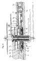
- la figure 1 est une vue en élévation du mécanisme indicateur de réserve de marche selon l'invention sur laquelle on a représenté plus particulièrement le rouage d'armage et le rouage d'affichage;
- la figure 2 est une vue analogue à celle de la figure 1 sur laquelle est représenté le rouage de désarmage, et
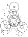
- la figure 3 est une vue en plan du mécanisme d'entraínement de l'indicateur de réserve de marche selon l'invention, les organes d'affichage ayant été omis.
- Figure 1 is an elevational view of the power reserve indicator mechanism according to the invention in which there is shown more particularly the gear train and the display train;
- FIG. 2 is a view similar to that of FIG. 1 in which the disarming train is shown, and
- Figure 3 is a plan view of the drive mechanism of the power reserve indicator according to the invention, the display members having been omitted.
Les vues en élévation des figures 1 et 2 illustrent partiellement une
pièce d'horlogerie du type montre-bracelet par exemple, équipée d'un
dispositif indicateur de réserve de marche conforme à la présente invention et
désigné dans son ensemble par la référence numérique générale 1. La montre
comprend un mouvement d'horlogerie muni d'un barillet (non représenté) dans
lequel est logé un ressort de barillet (également non représenté). Le
mouvement peut, selon le cas, être à remontage manuel ou automatique.
Dans ce dernier cas, un mécanisme à débrayage devra être prévu pour ne
pas fausser l'indication de réserve de marche lorsque le ressort du barillet est
armé au maximum et que la bride glisse dans le barillet.The elevation views of Figures 1 and 2 partially illustrate a
timepiece such as a wristwatch, equipped with a
power reserve indicator device according to the present invention and
designated as a whole by the
Le dispositif indicateur de réserve de marche 1 comprend un organe
d'affichage rotatif formé, par exemple, d'une aiguille de réserve de marche 2.
Cette aiguille 2, en fonction de la position relative qu'elle occupe vis-à-vis d'un
repère reporté sur le cadran 4 de la pièce d'horlogerie, indique au porteur la
réserve de marche disponible en fonction du nombre de tours d'armage du
ressort de barillet. The power
L'examen attentif des figures 1 à 3 permettra de comprendre le
fonctionnement du mécanisme d'entraínement de l'organe d'affichage 2 du
dispositif indicateur de réserve de marche selon l'invention.A careful examination of Figures 1 to 3 will allow us to understand the
operation of the drive mechanism of the
L'entraínement en rotation de l'aiguille 2 est réalisé à l'aide de deux
chaínes cinématiques entraínées par une première et une seconde prises de
force, à savoir respectivement la bonde de barillet et la denture extérieure
dudit barillet ou un mobile entraíné par ce barillet.The rotary drive of the
La première chaíne cinématique, encore appelée rouage d'armage, est
désignée dans son ensemble par la référence numérique générale 6. Cette
première chaíne cinématique 6 engrène avec une première entrée 8 d'un
engrenage différentiel 10.The first kinematic chain, also called the cogwheel, is
designated as a whole by the
La seconde chaíne cinématique, encore appelée rouage de désarmage,
est désignée dans son ensemble par la référence numérique générale 12.
Cette seconde chaíne cinématique 12 engrène avec une seconde entrée 14 de
l'engrenage différentiel 10 susmentionné.The second kinematic chain, also called disarming cog,
is designated as a whole by the
Enfin, la sortie 16 de l'engrenage différentiel 10 engrène avec une
troisième chaíne cinématique 18 encore appelée rouage d'affichage qui
entraíne l'aiguille d'affichage 2 en rotation.Finally, the
Nous allons maintenant examiner successivement les différents éléments qui composent les chaínes cinématiques énumérées ci-dessus.We will now successively examine the different elements that make up the kinematic chains listed above.
En ce qui concerne le rouage d'armage 6, un renvoi d'armage ZT est
chassé sur l'arbre de barillet (non représenté) de la montre. Le renvoi
d'armage ZT est en prise avec un mobile intermédiaire d'armage 20
comprenant un pignon intermédiaire d'armage ZR chassé sur l'axe de rotation
22 d'une roue intermédiaire d'armage ZS. Le mobile intermédiaire d'armage
20 entraíne à son tour par son pignon ZR un renvoi intermédiaire d'armage ZQ
chassé sur un axe de rotation 24. Ledit renvoi ZQ engrène ensuite avec la
première entrée 8 de l'engrenage différentiel 10. Cette première entrée 8 est
constituée par un mobile d'entrée de satellite 26 comportant un pignon
d'entrée de satellite Z1 chassé sur une roue d'entrée de satellite ZP.With regard to the
Comme on le comprendra mieux par la suite lorsqu'on décrira en détail
le fonctionnement du dispositif indicateur de réserve de marche 1 selon
l'invention, le pignon d'entrée de satellite Z1 entraíne deux pignons satellites Z2
qui, à leur tour, engrènent avec la denture intérieure Z3 d'une couronne de
différentiel 28. Les deux pignons satellites Z2 sont ajustés librement sur des
axes de rotation 30 portés par un renvoi de sortie de satellite Z4. As will be better understood later on when the operation of the power
En ce qui concerne le rouage d'affichage 18, celui-ci est constitué par
un mobile intermédiaire d'affichage 32 comprenant un pignon intermédiaire
d'affichage Z6 chassé sur une roue intermédiaire d'affichage Z5. Le mobile
intermédiaire d'affichage 32, disposé à la sortie 16 de l'engrenage différentiel
10, est entraíné en rotation par le renvoi de sortie de satellite Z4. A son tour,
ledit mobile intermédiaire d'affichage 32 engrène par son pignon Z6 avec une
roue d'affichage de réserve de marche ZRM sur l'axe 34 de laquelle est chassé
l'organe d'affichage 2.As regards the
Enfin, le rouage de désarmage 12 comprend un renvoi de désarmage
ZE qui engrène avec une seconde prise de force formée par la denture
extérieure du barillet ou par un mobile entraíné par ce barillet (non
représenté). Le renvoi de désarmage ZE est en prise avec un mobile
intermédiaire de désarmage 36 qui comprend un pignon intermédiaire de
désarmage ZC chassé sur l'axe de rotation d'une roue intermédiaire de
désarmage ZD. Le mobile intermédiaire de désarmage 36 entraíne à son tour
par son pignon ZC un renvoi intermédiaire de désarmage ZB. Ledit renvoi ZB
engrène ensuite avec la deuxième entrée 14 de l'engrenage différentiel 10.
Cette seconde entrée 14 est constituée par la denture extérieure ZA de la
couronne de différentiel 28.Finally, the
Lorsque la montre fonctionne normalement, c'est-à-dire lorsque le
ressort de barillet est en cours de désarmage, le renvoi de désarmage ZE est
entraíné en rotation par la denture extérieure du barillet ou par un mobile qui
engrène avec ladite denture extérieure. A son tour, le renvoi de désarmage ZE
engrène avec la roue ZD du mobile intermédiaire de désarmage 36 dont le
pignon ZC est en prise avec le renvoi intermédiaire de désarmage ZB. Ledit
renvoi ZB engrène ensuite avec la denture extérieure ZA de la couronne de
différentiel 28. Finalement, la couronne de différentiel 28 entraíne par sa
denture intérieure Z3 les deux pignons satellites Z2.When the watch operates normally, that is to say when the barrel spring is being disarmed, the disarming return Z E is rotated by the external toothing of the barrel or by a mobile which meshes with said external toothing . In turn, the disarming gear Z E meshes with the wheel Z D of the intermediate disarming mobile 36 whose pinion Z C is engaged with the intermediate disarming gear Z B. Said reference Z B then meshes with the external toothing Z A of the
Pendant le fonctionnement normal de la montre, le rouage d'armage 6
ne tourne pas. Par conséquent, la roue d'entrée de satellite ZP et le pignon
d'entrée de satellite Z1 chassé sur ladite roue ZP sont immobiles. Les deux
pignons satellites Z2, entraínés en rotation par la denture intérieure Z3 de la
couronne de différentiel 28, tournent ainsi sur eux-mêmes autour de leurs
axes 30 respectifs et roulent sur le pignon d'entrée de satellite Z1 qui est fixe.
Comme le renvoi de sortie de satellite Z4 porte les deux pignons satellites Z2, il
est entraíné en rotation par lesdits pignons satellites Z2. En tournant, le renvoi
de sortie de satellite Z4 engrène avec le mobile intermédiaire d'affichage 32
dont le pignon Z6 entraíne la roue d'affichage de réserve de marche ZRM et
l'aiguille d'affichage 2 qui est solidaire de ladite roue d'affichage ZRM. L'aiguille
d'affichage 2 effectue ainsi un déplacement angulaire en fonction de la réserve
de marche qui peut encore être assurée par l'armage du ressort de barillet.During normal operation of the watch, the
Lorsqu'on remonte la montre en vue du réarmage du ressort de
barillet, l'arbre de barillet entraíne le renvoi d'armage ZT en rotation. A son
tour, le renvoi d'armage ZT engrène avec la roue ZS du mobile intermédiaire
d'armage 20 dont le pignon ZR est en prise avec le renvoi intermédiaire
d'armage ZQ. Ledit renvoi ZQ engrène ensuite avec la roue d'entrée de satellite
ZP. Finalement, le pignon d'entrée de satellite Z1 qui tourne en même temps
que ladite roue d'entrée de satellite ZP entraíne les pignons satellites Z2 en
rotation.When we wind the watch for resetting the barrel spring, the barrel shaft causes the winding gear Z T to rotate. In turn, the winding gear Z T meshes with the wheel Z S of the intermediate winding
Pendant le réarmage de la montre, le rouage de désarmage 12 est
sensiblement immobile. Par conséquent, la couronne de différentiel 28 avec ses
dentures extérieure ZA et intérieure Z3 ne tourne pas. Les deux pignons
satellites Z2, entraínés en rotation par le pignon d'entrée de satellite Z1,
tournent ainsi sur eux-mêmes autour de leurs axes 30 respectifs et roulent
sur la denture intérieure Z3 de la couronne de différentiel 28 qui est fixe.
Comme le renvoi de sortie de satellite Z4 porte les deux pignons satellites Z2, il
est entraíné en rotation par lesdits pignons satellites Z2 dans le sens
contraire au précédent. En tournant, le renvoi de sortie de satellite Z4 engrène
avec le mobile intermédiaire d'affichage 32 dont le pignon Z6 entraíne la roue
d'affichage de réserve de marche ZRM et l'aiguille d'affichage 2 qui est liée à
ladite roue d'affichage ZRM. L'aiguille d'affichage 2 effectue ainsi un
déplacement angulaire en sens opposé au précédent en fonction de la réserve
de marche assurée par le nombre de tours d'armage du ressort de barillet.During the resetting of the watch, the disarming
On remarquera la compacité de la construction proposée,
particulièrement remarquable grâce à l'usage d'un engrenage différentiel 10
de type planétaire simple comprenant seulement un pignon d'entrée de
satellite Z1, deux pignons satellites Z2 et une couronne de différentiel 28 avec
une denture intérieure Z3 et une denture extérieure ZA. Ceci permet de réduire
de façon très substantielle l'épaisseur de la pièce d'horlogerie équipée du
dispositif selon l'invention. Ainsi, cette construction peut être montée sans
difficulté dans une montre-bracelet.Note the compactness of the proposed construction, particularly remarkable thanks to the use of a
On remarquera d'autre part que l'engrenage différentiel 10 est
positionné au centre du mouvement, sur la roue des heures 38. Ceci permet
avantageusement de distribuer l'affichage de l'indication de réserve de
marche sur toutes les positions du cadran indifféremment, et de s'adapter
ainsi à l'esthétique du cadran de la montre. Par ailleurs, comme l'engrenage
différentiel 10 est disposé au centre du mouvement, il est possible de le
réaliser avec des dimensions géométriques plus importantes que s'il était logé
à la périphérie du boítier, d'où une plus grande simplicité de fabrication.It will also be noted that the
Enfin, le fait que le rouage d'armage 6 et le rouage de désarmage 12
constituent deux trains d'engrenages parfaitement distincts offre à l'homme
du métier la possibilité d'adapter le mécanisme conforme à la présente
invention à un grand nombre de mouvements différents.Finally, the fact that the winding
Il va de soi que l'invention n'est pas limitée au mode de réalisation qui vient d'être décrit, et que des modifications et des variantes peuvent être envisagées sans sortir du cadre de l'invention.It goes without saying that the invention is not limited to the embodiment which has just been described, and that modifications and variations may be envisaged without departing from the scope of the invention.
Claims (11)
Priority Applications (6)
| Application Number | Priority Date | Filing Date | Title |
|---|---|---|---|
| AT99115389T ATE428958T1 (en) | 1999-08-04 | 1999-08-04 | DEVICE FOR DISPLAYING THE POWER RESERVE OF A WATCH |
| DE69940727T DE69940727D1 (en) | 1999-08-04 | 1999-08-04 | Device for displaying the power reserve of a watch |
| ES99115389T ES2325232T3 (en) | 1999-08-04 | 1999-08-04 | MARCH RESERVE INDICATOR DEVICE FOR A CLOCK PIECE. |
| EP99115389A EP1074897B1 (en) | 1999-08-04 | 1999-08-04 | Device for displaying the power-reserve of a timepiece |
| US09/631,381 US6685352B1 (en) | 1999-08-04 | 2000-08-03 | Timepiece power reserve indicator device |
| JP2000236689A JP4671477B2 (en) | 1999-08-04 | 2000-08-04 | Clock power holding amount display device |
Applications Claiming Priority (1)
| Application Number | Priority Date | Filing Date | Title |
|---|---|---|---|
| EP99115389A EP1074897B1 (en) | 1999-08-04 | 1999-08-04 | Device for displaying the power-reserve of a timepiece |
Publications (2)
| Publication Number | Publication Date |
|---|---|
| EP1074897A1 true EP1074897A1 (en) | 2001-02-07 |
| EP1074897B1 EP1074897B1 (en) | 2009-04-15 |
Family
ID=8238721
Family Applications (1)
| Application Number | Title | Priority Date | Filing Date |
|---|---|---|---|
| EP99115389A Expired - Lifetime EP1074897B1 (en) | 1999-08-04 | 1999-08-04 | Device for displaying the power-reserve of a timepiece |
Country Status (6)
| Country | Link |
|---|---|
| US (1) | US6685352B1 (en) |
| EP (1) | EP1074897B1 (en) |
| JP (1) | JP4671477B2 (en) |
| AT (1) | ATE428958T1 (en) |
| DE (1) | DE69940727D1 (en) |
| ES (1) | ES2325232T3 (en) |
Cited By (8)
| Publication number | Priority date | Publication date | Assignee | Title |
|---|---|---|---|---|
| EP1826633A1 (en) * | 2006-02-22 | 2007-08-29 | Frédéric Piguet S.A. | Self-winding watch with power reserve indicator |
| EP1995649A2 (en) | 2007-05-25 | 2008-11-26 | MPS Micro Precision Systems AG | Ball differential, in particular for a working reserve indicator of a mechanical timepiece movement |
| US7490977B2 (en) | 2007-03-13 | 2009-02-17 | Montres Breguet S.A. | Timepiece including a power reserve indicator device |
| CN101855601B (en) * | 2007-11-09 | 2012-07-04 | 绮年华钟表制造股份公司 | Mechanical watch having constant spring force |
| WO2014068375A1 (en) | 2012-10-30 | 2014-05-08 | Parmigiani Fleurier S.A. | Timepiece intended to indicate the power reserve |
| CN105301941A (en) * | 2014-07-21 | 2016-02-03 | Eta瑞士钟表制造股份有限公司 | Power reserve indicator for a timepiece |
| CN105589320A (en) * | 2014-11-07 | 2016-05-18 | 蒙特雷布勒盖股份有限公司 | Winding Device With One-Way Drive Arrangement |
| CN106502076A (en) * | 2015-09-07 | 2017-03-15 | 天津海鸥表业集团有限公司 | Display mechanism of power reserve |
Families Citing this family (12)
| Publication number | Priority date | Publication date | Assignee | Title |
|---|---|---|---|---|
| US7387253B1 (en) * | 1996-09-03 | 2008-06-17 | Hand Held Products, Inc. | Optical reader system comprising local host processor and optical reader |
| EP1260883A1 (en) * | 2001-05-22 | 2002-11-27 | Parmigiani Mesure et Art du Temps SA | Winding state indicator device |
| ATE534939T1 (en) * | 2004-02-04 | 2011-12-15 | Vaucher Mft Fleurier Sa | DEVICE FOR POWER RESERVE DISPLAY |
| JP4622274B2 (en) * | 2004-03-11 | 2011-02-02 | セイコーエプソン株式会社 | Spring remaining amount display mechanism and clock |
| CH699021B1 (en) * | 2006-03-17 | 2010-01-15 | Bnb Concept Sa | Basic module for timepiece, particularly wristwatch. |
| EP1914604A1 (en) * | 2006-10-19 | 2008-04-23 | Girard-Perregaux S.A. | Clock movement with constant torque energy transmission between the energy source and the mechanical oscillator |
| CH705252B1 (en) * | 2011-07-07 | 2015-11-30 | Blancpain Sa | watch movement comprising means for displaying a physical quantity. |
| EP2615506B1 (en) * | 2012-01-10 | 2014-06-25 | Montres Breguet SA | Device for rapid correction of a display system |
| CH710362A1 (en) | 2014-11-13 | 2016-05-13 | Société Anonyme De La Mft D'horlogerie Audemars Piguet & Cie | Device to split planetary gear for a timepiece. |
| EP3306415B1 (en) * | 2016-10-04 | 2020-05-20 | ETA SA Manufacture Horlogère Suisse | Mechanical clock movement with power-reserve detection |
| EP3627233B1 (en) * | 2018-09-19 | 2022-03-30 | ETA SA Manufacture Horlogère Suisse | Timepiece power reserve indicator mechanism |
| JP7327180B2 (en) * | 2020-01-27 | 2023-08-16 | セイコーエプソン株式会社 | clock |
Citations (4)
| Publication number | Priority date | Publication date | Assignee | Title |
|---|---|---|---|---|
| CH13340A (en) | 1896-11-18 | 1897-06-30 | Ernest Antoine | Device indicating the degree of development or winding of the barrel spring of watches and other long-running timepieces |
| US2774252A (en) * | 1954-09-04 | 1956-12-18 | Felsa S A | Differential gear |
| US3357174A (en) * | 1964-12-10 | 1967-12-12 | Zenith Montres | Watch with automatic winding |
| CH617815GA3 (en) * | 1978-09-04 | 1980-06-30 |
Family Cites Families (6)
| Publication number | Priority date | Publication date | Assignee | Title |
|---|---|---|---|---|
| US2698066A (en) * | 1952-07-18 | 1954-12-28 | Elgin Nat Watch Co | Power reserve indicator |
| US3901021A (en) * | 1973-06-25 | 1975-08-26 | Citizen Watch Co Ltd | Automatic winding watch |
| JP2757147B2 (en) * | 1995-07-07 | 1998-05-25 | セイコーインスツルメンツ株式会社 | Mechanical clock with a mainspring power display |
| CH690973A5 (en) * | 1996-12-19 | 2001-03-15 | Asulab Sa | Timepiece whose mechanism is driven by mechanical means and including a power reserve indicator device. |
| JPH11183642A (en) * | 1997-12-22 | 1999-07-09 | Seiko Instruments Inc | Clock with device displaying wound state of spring |
| JPH11183643A (en) * | 1997-12-25 | 1999-07-09 | Seiko Instruments Inc | Power reserve mechanism and display unit of power reserve mechanism |
-
1999
- 1999-08-04 ES ES99115389T patent/ES2325232T3/en not_active Expired - Lifetime
- 1999-08-04 AT AT99115389T patent/ATE428958T1/en not_active IP Right Cessation
- 1999-08-04 EP EP99115389A patent/EP1074897B1/en not_active Expired - Lifetime
- 1999-08-04 DE DE69940727T patent/DE69940727D1/en not_active Expired - Lifetime
-
2000
- 2000-08-03 US US09/631,381 patent/US6685352B1/en not_active Expired - Lifetime
- 2000-08-04 JP JP2000236689A patent/JP4671477B2/en not_active Expired - Lifetime
Patent Citations (4)
| Publication number | Priority date | Publication date | Assignee | Title |
|---|---|---|---|---|
| CH13340A (en) | 1896-11-18 | 1897-06-30 | Ernest Antoine | Device indicating the degree of development or winding of the barrel spring of watches and other long-running timepieces |
| US2774252A (en) * | 1954-09-04 | 1956-12-18 | Felsa S A | Differential gear |
| US3357174A (en) * | 1964-12-10 | 1967-12-12 | Zenith Montres | Watch with automatic winding |
| CH617815GA3 (en) * | 1978-09-04 | 1980-06-30 |
Cited By (14)
| Publication number | Priority date | Publication date | Assignee | Title |
|---|---|---|---|---|
| US7857502B2 (en) | 2006-02-22 | 2010-12-28 | Blancpain S.A. | Self-winding watch including an indicator of the power reserve |
| WO2007095767A2 (en) * | 2006-02-22 | 2007-08-30 | Frederic Piguet S.A. | Automatic winding watch comprising running reserve indication |
| WO2007095767A3 (en) * | 2006-02-22 | 2007-11-15 | Piguet Frederic Sa | Automatic winding watch comprising running reserve indication |
| EP1826633A1 (en) * | 2006-02-22 | 2007-08-29 | Frédéric Piguet S.A. | Self-winding watch with power reserve indicator |
| CN101390021B (en) * | 2006-02-22 | 2010-08-18 | 布朗潘有限公司 | Self-winding watch with power reserve indicator |
| US7490977B2 (en) | 2007-03-13 | 2009-02-17 | Montres Breguet S.A. | Timepiece including a power reserve indicator device |
| EP1995649A2 (en) | 2007-05-25 | 2008-11-26 | MPS Micro Precision Systems AG | Ball differential, in particular for a working reserve indicator of a mechanical timepiece movement |
| CN101855601B (en) * | 2007-11-09 | 2012-07-04 | 绮年华钟表制造股份公司 | Mechanical watch having constant spring force |
| WO2014068375A1 (en) | 2012-10-30 | 2014-05-08 | Parmigiani Fleurier S.A. | Timepiece intended to indicate the power reserve |
| CN105301941A (en) * | 2014-07-21 | 2016-02-03 | Eta瑞士钟表制造股份有限公司 | Power reserve indicator for a timepiece |
| CN105301941B (en) * | 2014-07-21 | 2018-02-02 | Eta瑞士钟表制造股份有限公司 | Energy reserve indicator for clock and watch |
| CN105589320A (en) * | 2014-11-07 | 2016-05-18 | 蒙特雷布勒盖股份有限公司 | Winding Device With One-Way Drive Arrangement |
| CN105589320B (en) * | 2014-11-07 | 2018-04-13 | 蒙特雷布勒盖股份有限公司 | Upper strip device with one-way drive mechanism |
| CN106502076A (en) * | 2015-09-07 | 2017-03-15 | 天津海鸥表业集团有限公司 | Display mechanism of power reserve |
Also Published As
| Publication number | Publication date |
|---|---|
| ATE428958T1 (en) | 2009-05-15 |
| ES2325232T3 (en) | 2009-08-28 |
| JP4671477B2 (en) | 2011-04-20 |
| JP2001074856A (en) | 2001-03-23 |
| DE69940727D1 (en) | 2009-05-28 |
| US6685352B1 (en) | 2004-02-03 |
| EP1074897B1 (en) | 2009-04-15 |
Similar Documents
| Publication | Publication Date | Title |
|---|---|---|
| EP1074897B1 (en) | Device for displaying the power-reserve of a timepiece | |
| EP2012199B1 (en) | Timepiece fitted with a device for the control of functions and/or time indications | |
| EP1970778A1 (en) | Timepiece comprising a device indicating the power reserve | |
| EP2392976A2 (en) | Mechanism for indication of the lunar phases | |
| EP3483664A1 (en) | Clockwork mechanism for displaying the lunar day and the phase of the moon, with correction system with dual drive train | |
| EP2515186A1 (en) | Gear-train for timepiece | |
| EP3008523B1 (en) | Calendar mechanism for a clock movement | |
| EP2080067A2 (en) | Indicating hand for timepiece, movement to drive said indicating hand and corresponding timepiece | |
| EP1962155A1 (en) | Chronograph | |
| CH702422B1 (en) | Timepiece. | |
| CH713109B1 (en) | Clockwork movement comprising at least two tourbillons. | |
| WO2014177290A1 (en) | Timepiece including a device for displaying the date | |
| EP3477402A2 (en) | Device for displaying the phases of the moon | |
| CH713649B1 (en) | Timepiece comprising a removable cover device for regulating member of a watch movement. | |
| EP2156250B1 (en) | Device for correction of a display mechanism for a timepiece | |
| FR2921164A1 (en) | Device i.e. sequential display module, for visualizing e.g. watch complication, has mechanical module and masking disk integrated in casing including visualizable parts and units associated to visualizable parts | |
| EP1353244B1 (en) | Timepiece with oblong shaped case | |
| CH688171B5 (en) | additional mechanism of astronomical representation for timepieces. | |
| CH689028A5 (en) | Display device for timepiece or stop-watch | |
| CH718424A1 (en) | Timepiece with a display device comprising at least one ornamental mobile. | |
| EP0724204A1 (en) | Time zone watch with analogical display | |
| CH717255B1 (en) | Mechanical watch movement with date display. | |
| CH348658A (en) | Wristwatch-alarm clock | |
| CH689027A5 (en) | Clock piece with additional module and time element | |
| CH698141B1 (en) | Mechanical watch movement. |
Legal Events
| Date | Code | Title | Description |
|---|---|---|---|
| PUAI | Public reference made under article 153(3) epc to a published international application that has entered the european phase |
Free format text: ORIGINAL CODE: 0009012 |
|
| AK | Designated contracting states |
Kind code of ref document: A1 Designated state(s): AT BE CH CY DE DK ES FI FR GB GR IE IT LI LU MC NL PT SE |
|
| AX | Request for extension of the european patent |
Free format text: AL;LT;LV;MK;RO;SI |
|
| 17P | Request for examination filed |
Effective date: 20010807 |
|
| AKX | Designation fees paid |
Free format text: AT BE CH CY DE DK ES FI FR GB GR IE IT LI LU MC NL PT SE |
|
| 17Q | First examination report despatched |
Effective date: 20070514 |
|
| GRAP | Despatch of communication of intention to grant a patent |
Free format text: ORIGINAL CODE: EPIDOSNIGR1 |
|
| GRAS | Grant fee paid |
Free format text: ORIGINAL CODE: EPIDOSNIGR3 |
|
| GRAA | (expected) grant |
Free format text: ORIGINAL CODE: 0009210 |
|
| AK | Designated contracting states |
Kind code of ref document: B1 Designated state(s): AT BE CH CY DE DK ES FI FR GB GR IE IT LI LU MC NL PT SE |
|
| REG | Reference to a national code |
Ref country code: GB Ref legal event code: FG4D Free format text: NOT ENGLISH Ref country code: CH Ref legal event code: EP |
|
| REG | Reference to a national code |
Ref country code: IE Ref legal event code: FG4D |
|
| REF | Corresponds to: |
Ref document number: 69940727 Country of ref document: DE Date of ref document: 20090528 Kind code of ref document: P |
|
| REG | Reference to a national code |
Ref country code: CH Ref legal event code: NV Representative=s name: ICB INGENIEURS CONSEILS EN BREVETS SA |
|
| REG | Reference to a national code |
Ref country code: ES Ref legal event code: FG2A Ref document number: 2325232 Country of ref document: ES Kind code of ref document: T3 |
|
| PG25 | Lapsed in a contracting state [announced via postgrant information from national office to epo] |
Ref country code: PT Free format text: LAPSE BECAUSE OF FAILURE TO SUBMIT A TRANSLATION OF THE DESCRIPTION OR TO PAY THE FEE WITHIN THE PRESCRIBED TIME-LIMIT Effective date: 20090915 Ref country code: FI Free format text: LAPSE BECAUSE OF FAILURE TO SUBMIT A TRANSLATION OF THE DESCRIPTION OR TO PAY THE FEE WITHIN THE PRESCRIBED TIME-LIMIT Effective date: 20090415 Ref country code: AT Free format text: LAPSE BECAUSE OF FAILURE TO SUBMIT A TRANSLATION OF THE DESCRIPTION OR TO PAY THE FEE WITHIN THE PRESCRIBED TIME-LIMIT Effective date: 20090415 |
|
| PG25 | Lapsed in a contracting state [announced via postgrant information from national office to epo] |
Ref country code: SE Free format text: LAPSE BECAUSE OF FAILURE TO SUBMIT A TRANSLATION OF THE DESCRIPTION OR TO PAY THE FEE WITHIN THE PRESCRIBED TIME-LIMIT Effective date: 20090715 |
|
| REG | Reference to a national code |
Ref country code: IE Ref legal event code: FD4D |
|
| PG25 | Lapsed in a contracting state [announced via postgrant information from national office to epo] |
Ref country code: IE Free format text: LAPSE BECAUSE OF FAILURE TO SUBMIT A TRANSLATION OF THE DESCRIPTION OR TO PAY THE FEE WITHIN THE PRESCRIBED TIME-LIMIT Effective date: 20090415 Ref country code: DK Free format text: LAPSE BECAUSE OF FAILURE TO SUBMIT A TRANSLATION OF THE DESCRIPTION OR TO PAY THE FEE WITHIN THE PRESCRIBED TIME-LIMIT Effective date: 20090415 |
|
| PLBE | No opposition filed within time limit |
Free format text: ORIGINAL CODE: 0009261 |
|
| STAA | Information on the status of an ep patent application or granted ep patent |
Free format text: STATUS: NO OPPOSITION FILED WITHIN TIME LIMIT |
|
| BERE | Be: lapsed |
Owner name: FREDERIC PIGUET S.A. Effective date: 20090831 |
|
| 26N | No opposition filed |
Effective date: 20100118 |
|
| PG25 | Lapsed in a contracting state [announced via postgrant information from national office to epo] |
Ref country code: MC Free format text: LAPSE BECAUSE OF NON-PAYMENT OF DUE FEES Effective date: 20090831 |
|
| PG25 | Lapsed in a contracting state [announced via postgrant information from national office to epo] |
Ref country code: BE Free format text: LAPSE BECAUSE OF NON-PAYMENT OF DUE FEES Effective date: 20090831 |
|
| PG25 | Lapsed in a contracting state [announced via postgrant information from national office to epo] |
Ref country code: GR Free format text: LAPSE BECAUSE OF FAILURE TO SUBMIT A TRANSLATION OF THE DESCRIPTION OR TO PAY THE FEE WITHIN THE PRESCRIBED TIME-LIMIT Effective date: 20090716 |
|
| PG25 | Lapsed in a contracting state [announced via postgrant information from national office to epo] |
Ref country code: LU Free format text: LAPSE BECAUSE OF NON-PAYMENT OF DUE FEES Effective date: 20090804 |
|
| PG25 | Lapsed in a contracting state [announced via postgrant information from national office to epo] |
Ref country code: CY Free format text: LAPSE BECAUSE OF FAILURE TO SUBMIT A TRANSLATION OF THE DESCRIPTION OR TO PAY THE FEE WITHIN THE PRESCRIBED TIME-LIMIT Effective date: 20090415 |
|
| REG | Reference to a national code |
Ref country code: CH Ref legal event code: PFUS Owner name: BLANCPLAIN SA, CH Free format text: FORMER OWNER: FREDERIC PIGUET S.A., CH |
|
| REG | Reference to a national code |
Ref country code: DE Ref legal event code: R082 Ref document number: 69940727 Country of ref document: DE Representative=s name: SPARING - ROEHL - HENSELER, DE Effective date: 20120606 Ref country code: DE Ref legal event code: R081 Ref document number: 69940727 Country of ref document: DE Owner name: BLANCPAIN S.A., CH Free format text: FORMER OWNER: FREDERIC PIGUET S.A., LE BRASSUS, CH Effective date: 20120606 |
|
| PGFP | Annual fee paid to national office [announced via postgrant information from national office to epo] |
Ref country code: NL Payment date: 20120730 Year of fee payment: 14 |
|
| REG | Reference to a national code |
Ref country code: NL Ref legal event code: V1 Effective date: 20140301 |
|
| PG25 | Lapsed in a contracting state [announced via postgrant information from national office to epo] |
Ref country code: NL Free format text: LAPSE BECAUSE OF NON-PAYMENT OF DUE FEES Effective date: 20140301 |
|
| REG | Reference to a national code |
Ref country code: FR Ref legal event code: PLFP Year of fee payment: 17 |
|
| REG | Reference to a national code |
Ref country code: FR Ref legal event code: PLFP Year of fee payment: 18 |
|
| REG | Reference to a national code |
Ref country code: FR Ref legal event code: PLFP Year of fee payment: 19 |
|
| PGFP | Annual fee paid to national office [announced via postgrant information from national office to epo] |
Ref country code: IT Payment date: 20170719 Year of fee payment: 19 Ref country code: ES Payment date: 20170904 Year of fee payment: 19 Ref country code: GB Payment date: 20170719 Year of fee payment: 19 |
|
| REG | Reference to a national code |
Ref country code: FR Ref legal event code: PLFP Year of fee payment: 20 |
|
| PGFP | Annual fee paid to national office [announced via postgrant information from national office to epo] |
Ref country code: FR Payment date: 20180720 Year of fee payment: 20 Ref country code: DE Payment date: 20180719 Year of fee payment: 20 |
|
| PGFP | Annual fee paid to national office [announced via postgrant information from national office to epo] |
Ref country code: CH Payment date: 20180726 Year of fee payment: 20 |
|
| GBPC | Gb: european patent ceased through non-payment of renewal fee |
Effective date: 20180804 |
|
| PG25 | Lapsed in a contracting state [announced via postgrant information from national office to epo] |
Ref country code: IT Free format text: LAPSE BECAUSE OF NON-PAYMENT OF DUE FEES Effective date: 20180804 |
|
| REG | Reference to a national code |
Ref country code: DE Ref legal event code: R071 Ref document number: 69940727 Country of ref document: DE |
|
| REG | Reference to a national code |
Ref country code: CH Ref legal event code: PL |
|
| REG | Reference to a national code |
Ref country code: ES Ref legal event code: FD2A Effective date: 20190918 |
|
| PG25 | Lapsed in a contracting state [announced via postgrant information from national office to epo] |
Ref country code: ES Free format text: LAPSE BECAUSE OF NON-PAYMENT OF DUE FEES Effective date: 20180805 Ref country code: GB Free format text: LAPSE BECAUSE OF NON-PAYMENT OF DUE FEES Effective date: 20180804 |