EP1074656A2 - Stoffauflauf - Google Patents
Stoffauflauf Download PDFInfo
- Publication number
- EP1074656A2 EP1074656A2 EP00107659A EP00107659A EP1074656A2 EP 1074656 A2 EP1074656 A2 EP 1074656A2 EP 00107659 A EP00107659 A EP 00107659A EP 00107659 A EP00107659 A EP 00107659A EP 1074656 A2 EP1074656 A2 EP 1074656A2
- Authority
- EP
- European Patent Office
- Prior art keywords
- headbox
- suspension
- headbox according
- area
- elements
- Prior art date
- Legal status (The legal status is an assumption and is not a legal conclusion. Google has not performed a legal analysis and makes no representation as to the accuracy of the status listed.)
- Withdrawn
Links
Images


Classifications
-
- D—TEXTILES; PAPER
- D21—PAPER-MAKING; PRODUCTION OF CELLULOSE
- D21F—PAPER-MAKING MACHINES; METHODS OF PRODUCING PAPER THEREON
- D21F1/00—Wet end of machines for making continuous webs of paper
- D21F1/02—Head boxes of Fourdrinier machines
-
- D—TEXTILES; PAPER
- D21—PAPER-MAKING; PRODUCTION OF CELLULOSE
- D21F—PAPER-MAKING MACHINES; METHODS OF PRODUCING PAPER THEREON
- D21F1/00—Wet end of machines for making continuous webs of paper
- D21F1/02—Head boxes of Fourdrinier machines
- D21F1/026—Details of the turbulence section
-
- D—TEXTILES; PAPER
- D21—PAPER-MAKING; PRODUCTION OF CELLULOSE
- D21F—PAPER-MAKING MACHINES; METHODS OF PRODUCING PAPER THEREON
- D21F1/00—Wet end of machines for making continuous webs of paper
- D21F1/02—Head boxes of Fourdrinier machines
- D21F1/028—Details of the nozzle section
Definitions
- the invention relates to a headbox, in particular a multilayer headbox, a paper machine with at least one stock suspension feed, one having a plurality of tubular elements Diffuser block and a headbox nozzle, which a plurality of machine-wide suspension channels, which between a Upper and one lower wall of the headbox nozzle by at least two, preferably formed three machine-wide dividing elements and through which the stock suspension on a sieve or between two sieves is guided, the suspension channels forming a first area I and a second, downstream region II, wherein the first region I by flat, converging in the direction of flow, machine-wide boundary surfaces is formed, and each Separator in the second area II a greater convergence of its Has surfaces than in the first area I.
- FIG. 6 shows a headbox, which has a headbox nozzle with three internal dividing elements that form the material suspension of the individual layers separate this headbox.
- the dividers have an extension in the nozzle outlet area and then a worsening (convergence), which should lead to the fact that between the individual suspension layers brought together after the separating elements only minimal mixing tendencies arise.
- the aim of the invention is to provide a headbox of the type mentioned create, at the same time as high a strength as possible also ensures the highest possible beam stability and good formation are.
- the streaked structure (tiger stripes) in the paper is to be avoided or at least be reduced.
- tubular Elements of the diffuser block are associated with vortex-forming agents, to in the partial suspension streams passed through these tubular elements to generate secondary eddy currents, which are the Primary flow of these partial suspension flows superimpose, and that all Separating elements of the headbox nozzle have a contour and arrangement, which have an equally long second area II for each suspension channel with an identical cross-sectional profile.
- the change and absolute size of the cross section is the free, flowed area related to a position in the machine direction to understand, with the variation of flow directions first is not included.
- the vortex-forming means can in particular be designed in this way as described in US-A-5,876,564.
- the application too of these vortex forming agents and the corresponding procedure for mixing the partial suspension streams can be provided as this is described in US-A-5 876 564. This becomes the revelation this US-A-5 876 564 also fully in the disclosure of the present Registration included.
- Headbox is the rotational movement of a respective secondary vortex flow generally around the longitudinal axis of the respective tubular Element-oriented.
- the vortex formation can, for example, by a corresponding geometry and / or the nature of the inner surface of a respective tubular Elements or a respective pipe insert.
- the vortex-forming include Means at least one of a respective tubular element 18 assigned insert and / or attachment through which the respective partial suspension flow to generate the secondary vortex flow accordingly can be influenced.
- At least one attachment or insert for one Influencing of the respective partial suspension flow is carried out and preferably at least one pressure pulse generating element includes. It can be a respective tubular element or tube insert, for example at least two and preferably two be assigned to twelve pressure pulse generating elements.
- At least one Pressure pulse generating element provided by an acoustic Element is formed.
- At least one Pressure pulse generating element is provided by an electromagnetic Element is formed.
- At least one tubular element or at least one tube insert is provided which or the inlet provided as a flat section for receiving the Stock suspension from a distributor and one as an elongated section provided provided outlet, which opens into the headbox nozzle.
- At least one insertable into the diffuser block Pipe insert is provided to suspend stock from a manifold to record.
- Headbox is at least one insert provided by a body arranged within a respective tubular element is that has at least two wings and for vortex formation by at least one, preferably at least three in the longitudinal direction of the tubular member spaced apart, the tubular member surrounding magnetic rings can be acted upon accordingly.
- the body can have two to twelve wings, for example.
- the body is with outer wings.
- the cross section of the suspension channels can vary expand or reduce the second area. Is also a constant Cross section in area II possible.
- the separating elements have a Have tapering, preferably the degree of convergence of the The surface of the tapered ends of all separating elements must be the same should, so that a turbulence-free flow arises.
- the formation of the headbox is particularly advantageous if the degree the divergence or convergence of all suspension channels in the second area II is the same size. This means that all suspension channels have the same opening angle in the second area II.
- the opening angle of the suspension channels in the second area II should are between 20 ° convergence and 120 ° divergence, preferably one Range between 5 ° convergence and 7 ° divergence is recognized.
- headbox provides that the course of the top wall and / or the bottom wall - at least in the second area II of the suspension channel - with regard to those in contact with the suspension Surface (s) reflecting the course of the surface of the adjacent separating element is / are. This is supposed to further improvement with regard to the design of the outer suspension channels in relation to the internal suspension channels can be achieved.
- the radius center point M is preferably of the circular arc on the center line of the resulting suspension jet.
- Another preferred embodiment provides that the center of the radius M of the circular arc on the bisector of the suspension in contact Areas of the top and bottom walls in the second area II of the headbox nozzle lies.
- the diffuser tubes being arranged in machine-wide rows are proposed, the separators between the rows let the diffuser tubes begin.
- An advantageous length of the second area II of the stock suspension channels is 0 - 4 dm, preferably about 0.5 - 2 dm.
- the preferred headbox three dividers and four suspension channels on.
- separating elements are preferred, their greatest and smallest thickness in the range of maximum 5 cm and minimum 0.5 mm, preferably maximum 1 cm and minimum 3 mm.
- the suspension channels at least in the second Area II are congruent. That is, in each one Suspension channel, including the two outer suspension channels, the respective suspension is led through absolutely identical cross sections, not only changing the cross sections in all Suspension channels is the same, but also the individual curvatures the channels are identical or mirrored identical.
- the stock suspension experiences absolute equal treatment in all Channels - also with regard to the alignment of the speed vectors - making the prevention of streaky formation of the paper particularly is favored.
- the invention is therefore essentially based on the idea ensure that there is a last area in the headbox before ejection the stock suspension from the headbox nozzle in which the Stock suspension in all individual layers - i.e. the suspension channels - is treated equally at the same time, and that the individual Suspension flows of the suspension channels meet in a moment, in which all individual suspension layers have the same current as possible Flow state and the same past flow states have as long a period as possible.
- the flow state of the Suspension flow mainly affects the speed, acceleration, turbulence, if applicable, and, if applicable entire vector field of flow velocities.
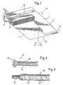
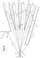
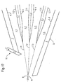
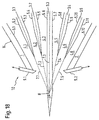
- FIG. 1 to 18 is a purely schematic representation Headbox 10 shown, a variety of tubular elements 18 comprehensive diffuser block 16 or turbulence generator with vortex-forming Means 20 (see e.g. Figure 1) and its headbox nozzle 14 in the manner shown in particular in Figures 14 to 18 with separating elements 3.1 to 3.5 is provided.
- the separating elements are in FIG 3.1 to 3.5 omitted only for better illustration of the diffuser block 16.
- FIG. 1 there are also corresponding ones Separating elements are provided, as shown in particular in the figures 14 to 18 are described in more detail.
- the stock suspension is the Diffuser block 16 fed through a distributor 12 through which the suspension is distributed accordingly across the width of the headbox.
- the opening into the exit gap 22 The nozzle chamber is connected to the distributor 12 via the diffuser block 16 connected.
- vortex forming means 20 are in the through the tubular Partial suspension flows passed through elements 18 secondary eddy currents generated, which is generally in the machine direction superimposed primary flow of these partial suspension flows.
- the rotational movement of a respective secondary vortex flow preferably generally about the longitudinal axis of the respective tubular Elements 18 oriented.
- the respective secondary vortex flow especially generated so that in the respective tubular Element 18 is a generally helical resulting total flow results that runs generally in the machine direction and that has superimposed secondary eddy current.
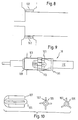
- the vortex formation can, for example, by a corresponding geometry and / or the nature of the inner surface of a respective tubular Elements 18 (see, for example, Figures 3 to 5) or a respective one Pipe insert 34 (see FIG. 2, for example).
- FIG. 2 is a schematic representation of one with such vortex-forming Averaged insert tube 34 shown.
- This insert tube 34 has an inlet for receiving provided as a flat section 36 the stock suspension from the manifold 12 and one as an elongated section 38 provided outlet, which opens into the headbox nozzle 14.
- the vortex-forming means 20 comprise a helical one inner groove.
- Such a tube insert 34 can, for example, be in existing ones tubular elements 18 are used to achieve the desired secondary To produce vortex flow.
- FIG 3 shows a schematic representation of one with the vortex-forming Tubular element 18 of a step diffuser block provided with means 20.
- the vortex-forming means 20 again comprise a helical one inner groove.
- the pitch of this groove can change in the axial direction change as indicated at positions 20 ', 20' 'and 20' ''. How can be seen from Figure 3, this pitch changes in particular between positions 20 '' and 20 '' '.
- FIGs 4 and 5 also each show a vortex-forming Means 20 provided tubular element 18. Both embodiments each again comprise an inlet provided as a flat section 48 for receiving the stock suspension from the distributor 12 (see FIG. 1) and an outlet provided as an elongated section 52, 54, which in the Headbox nozzle 14 opens.
- the vortex forming agents include here for example, inclined portions provided on the respective flat portions 48 Ribs or grooves 20 'and inner helical grooves 20' 'in the elongated sections 52, 54 and in between them and the flat ones Sections 48 provided curved transition areas 50.
- Die elongated sections 52, 54 each comprise one in the present case converging on the respective flat section 48 Section 52.
- Figure 6 shows a purely schematic cross-sectional view of a tubular Elements 18 with associated pressure pulse generating elements 102 in Range of a between a section of smaller diameter and a section of larger diameter provided.
- the pressure pulse generating elements 102 is provided at the beginning of the larger diameter section.
- FIG. 7 in the present case is eight such pressure pulse generation elements 102 distributed over the circumference of the tubular element 18.
- the pressure pulse generating elements 102 can be flush complete with the inner wall of the tubular element 18.
- the vortex-forming means 20 thus include the pressure pulse generating elements 102 formed inserts and / or Essays through which the respective suspension partial flows for generation the secondary eddy currents can be influenced accordingly.
- the pressure pulse generating elements 102 can be, for example are acoustic and / or electromagnetic elements.
- the vortex-forming Means 20 also include at least one insert 102 which by one arranged within a respective tubular element 18 Body 105 is formed, which has at least two wings 107.
- the respective tubular element 18 For example, a magnetically actuable device that serves to form eddies Body 105 used, for example with four or three outer wings 107 is provided.
- This body 105 provided with wings 107 is in the present case by three in the longitudinal direction of the tubular element 18 spaced apart magnetic rings surrounding the tubular element 18 109, 111, 113 can be acted upon accordingly.
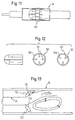
- Figures 11 and 12 show a schematic representation tubular element 18 into which a vortex-forming magnetic actuatable annular body 105 with three or four inner wings 121 is inserted.
- FIG. 13 again shows a further embodiment in a purely schematic representation a pressure pulse generating element 102, which in the present Case is annular.
- this annular pressure pulse generating element 102 is End of an insert tube 34 inserted into a tubular element 18 provided by which a left section of smaller diameter and a right section of larger diameter is formed, the annular pressure pulse generating element 102 in the area of the circular curved transition 116 is provided.
- the flow course is indicated with C.
- vortex-forming means can be designed in particular and be used as described in US-A-5 876 564 is.
- FIG. 14 shows a longitudinal section through the nozzle area of the Headbox 10 in a schematic representation.
- the headbox nozzle will formed by an upper wall 1 and a lower wall 2, between which there are three separators 3.1 to 3.3.
- the suspension touched Surfaces 5.1 to 5.8 - both of the separators 3.1 to 3.3 as well the top and bottom wall 1, 2 - form four machine-wide suspension channels 4.1 to 4.4, which have a first region I upstream, in which the surfaces 5.1 to 5.8 in contact with the suspension approach linearly and then have a second area II, in which the Surfaces 5.1 to 5.8 diverge.
- the surfaces 5.2 and 5.3, 5.4 and 5.5, 5.6 and 5.7 of the Pointing separating elements form bisectors in the second area II 6.1 to 6.4, which are drawn with dots in the illustration. Farther are the bisectors 7.1 to 7.3 of the converging surfaces the dividing elements 3.1 to 3.3 shown in dashed lines.
- the bisectors intersect 7.1 to 7.3 of the tapering of the separating elements in one point B, and the bisector of the two outer suspension channels 6.1, 6.4 meet at point A '. All points A, A ', M and B lie on a common straight line.
- FIG. 15 An improved design of the headbox nozzle of the invention Headbox is shown schematically in longitudinal section in Figure 15. This figure also shows the nozzle area of the headbox 10 with the Upper wall 1 and the lower wall 2 and three internal dividers 3.1 to 3.3.
- the material suspension channels 4.1 to 4.4 are of this type trained that all second areas II of the suspension channels over a Bisector 6.1 to 6.4, which are all in one Meet point A, whereby also the bisector 7.1 to 7.3 the separating elements 3.1 to 3.3 meet at point B. Farther the ends of the separating lamellae are on a circular base with a Radius center M.
- the peculiarity of the design of the object 15 is that the intersection points A, B and the center of radius M of the arc all coincide in one point.
- FIG. 16 Another variant of a headbox is shown in FIG. During the headboxes of Figures 14 and 15 - due to their symmetrical Structure - essentially for twin-wire machines, in particular GAP former are suitable, is a headbox for in Figure 16 a Fourdrinier sieve is shown, its special feature compared to FIG. 14 lies in the fact that the lower wall 2 is drawn somewhat beyond the circular arc is. Otherwise, the headbox in FIG. 16 corresponds to the illustration from FIG. 14.
- FIG. 17 shows the variation of the headbox according to FIG. 16.
- the headbox on top wall 1 has an additional one Aperture 9, with which the free nozzle outlet gap is set in a known manner can be.
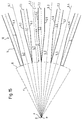
- FIG. 18 shows a further variation of a headbox according to the invention.
- This is a multi-layer headbox, at which in the upper half three suspension channels 4.1 to 4.3 and in the lower half of the headbox a further three suspension channels 4.4 to 4.6 are shown.
- the two halves of the headbox are through a central separating element 3.3 separated, the length of which Nozzle outlet gap formed by the two orifices 9.1 and 9.2 is towered over.
- the bisectors of the tapering of the separating elements 7.1 to 7.5 intersect at intersection B, which is the case in this embodiment of the headbox on the center line of the middle separating element 3.3 lies.
- Both panels 9.1 and 9.2, which on the top wall 1 or the lower wall 2 are attached, are adjustable, so that through this the respective nozzle outlet gap of the upper one or lower half of the headbox is adjustable.
Landscapes
- Nozzles (AREA)
- Paper (AREA)
Abstract
Description
- Figur 1
- eine schematische perspektivische Darstellung eines Stoffauflaufs mit einem wirbelbildende Mittel aufweisenden Diffusorblock und einer Trennelemente (vgl. die Figuren 14 bis 18) aufweisenden Stoffauflaufdüse, wobei die Trennelemente zur besseren Darstellung des Diffusorblocks weggelassen sind,
- Figur 2
- eine schematische Darstellung eines mit wirbelbildenden Mitteln versehenen Einsatzrohres,
- Figur 3
- eine schematische Darstellung eines mit wirbelbildenden Mitteln versehenen rohrartigen Elements eines Stufen-Diffusorblocks,
- Figur 4
- eine schematische Darstellung einer weiteren Ausführungsform eines mit wirbelbildenden Mitteln versehenen rohrartigen Elements,
- Figur 5
- eine schematische Darstellung einer weiteren Ausführungsform eines mit wirbelbildenden Mitteln versehenen rohrartigen Elements,
- Figur 6
- eine schematische Querschnittsansicht eines rohrartigen Elements mit zugeordneten Druckimpulserzeugungselementen,
- Figur 7
- eine Ansicht des rohrartigen Elements gemäß Figur 6 in Richtung des Pfeiles A,
- Figur 8
- eine schematische Querschnittsansicht eines rohrartigen Elements mit zugeordneten Druckimpulserzeugungselementen,
- Figur 9
- eine schematische Querschnittsansicht eines rohrartigen Elements mit einem der Wirbelbildung dienenden magnetisch betätigbaren Körper, der mit äußeren Flügeln versehen ist,
- Figur 10
- eine schematische Seiten- und Vorderansicht des mit äußeren Flügeln versehenen Körpers gemäß Figur 9,
- Figur 11
- eine schematische Querschnittsansicht eines rohrartigen Elements mit einem der Wirbelbildung dienenden magnetisch betätigbaren ringförmigen Körper, der mit inneren Flügeln versehen ist,
- Figur 12
- eine schematische Seiten- und Vorderansicht des mit inneren Flügeln versehenen Körpers gemäß Figur 11,
- Figur 13
- eine schematische Querschnittsansicht einer weiteren Ausführungsform eines Druckimpulserzeugungselements in Form eines Ringes,
- Figur 14
- eine symmetrische Stoffauflaufdüse des Stoffauflaufs mit ebener Ober- und Unterwand,
- Figur 15
- eine symmetrische Stoffauflaufdüse des Stoffauflaufs mit Knick in den suspensionsberührten Flächen von Ober- und Unterwand,
- Figur 16
- eine asymmetrische Stoffauflaufdüse des Stoffauflaufs mit ebener Ober- und Unterwand,
- Figur 17
- eine Stoffauflaufdüse eines Langsieb-Stoffauflaufes oder Einschicht-Gap-Former-Stoffauflaufes und
- Figur 18
- eine Stoffauflaufdüse eines Mehrschicht-Stoffauflaufes.
- 1
- Erste Wand, Oberwand
- 2
- Zweite Wand, Unterwand
- 3.1 - 3.5
- Trennelemente
- 4.1 - 4.6
- Suspensionskanäle
- 5.1 - 5.12
- Begrenzungsflächen
- 6.1 - 6.4
- Winkelhalbierende der Suspensionskanäle im zweiten Bereich
- 7.1 - 7.5
- Winkelhalbierende der Zuspitzung der Trennelemente
- 9, 9.1, 9.2
- Blende
- 8
- Kreisbogen
- 10
- Stoffauflauf
- 12
- Verteiler
- 14
- Stoffauflaufdüse
- 16
- Diffusorblock
- 18
- rohrartige Blende
- 20
- wirbelbildende Mittel
- 22
- Austrittsspalt
- 24
- flächiger Austrittsstrahl
- 34
- Rohreinsatz
- 36
- flacher Abschnitt
- 38
- länglicher Abschnitt
- 48
- flacher Abschnitt
- 50
- Übergangsbereich
- 52, 54
- längerer Abschnitt
- 101
- Einsatz
- 102
- Druckimpulserzeugungselement
- 105
- Körper
- 7
- äußere Flügel
- 9
- Magnetring
- 111
- Magnetring
- 113
- Magnetring
- 116
- Übergang
- 121
- innere Flügel
- A
- Schnittpunkt der Winkelhalbierenden
- B
- Schnittpunkt der Winkelhalbierenden
- C
- Strömungsverlauf
Claims (42)
- Stoffauflauf (10), insbesondere Mehrschichten-Stoffauflauf, einer Papiermaschine mit mindestens einer Stoffsuspensionszuführung, einem eine Vielzahl von rohrartigen Elementen (18) aufweisenden Diffusorblock (16) und einer Stoffauflaufdüse (14), welche eine Mehrzahl von maschinenbreiten Suspensionskanälen (4.1 bis 4.6) aufweist, die zwischen einer Ober- und einer Unterwand (1 bzw. 2) der Stoffauflaufdüse (14) durch mindestens zwei, vorzugsweise drei maschinenbreit verlaufende Trennelemente (3.1 bis 3.5) gebildet werden und durch welche die Stoffsuspension auf ein Sieb oder zwischen zwei Siebe geführt wird, wobei die Suspensionskanäle (4.1 bis 4.6) einen ersten Bereich I und einen zweiten stromabwärts gelegenen Bereich II aufweisen, wobei der erste Bereich I durch ebene, in Strömungsrichtung konvergierende, maschinenbreite Begrenzungsflächen gebildet wird, und wobei jedes Trennelement (3.1 bis 3.5) im zweiten Bereich II eine stärkere Konvergenz seiner Oberfläche aufweist als im ersten Bereich I,
dadurch gekennzeichnet,
daß den rohrartigen Elementen (18) des Diffusorblocks (16) wirbelbildende Mittel (20) zugeordnet sind, um in den durch diese rohrartigen Elemente (18) hindurchgeführten Suspensionsteilströmen sekundäre Wirbelströmungen zu erzeugen, die sich der Primärströmung dieser Suspensionsteilströme überlagern, und daß alle Trennelemente (3.1 bis 3.5) der Stoffauflaufdüse (14) eine Kontur und Anordnung aufweisen, die für jeden Suspensionskanal (4.1 bis 4.6) einen gleich langen zweiten Bereich II mit identischem Querschnittsverlauf ergibt. - Stoffauflauf nach Anspruch 1,
dadurch gekennzeichnet,
daß die Rotationsbewegung einer jeweiligen sekundären Wirbelströmung allgemein um die Längsachse des jeweiligen rohrförmigen Elements (18) orientiert ist. - Stoffauflauf nach Anspruch 1 oder 2,
dadurch gekennzeichnet,
daß die jeweilige sekundäre Wirbelströmung so erzeugt ist, daß sich in dem jeweiligen rohrförmigen Element (18) eine allgemein wendelförmige resultierende Gesamtströmung ergibt. - Stoffauflauf nach einem der vorhergehenden Ansprüche,
dadurch gekennzeichnet,
daß die Wirbelbildung durch eine entsprechende Geometrie und/oder Beschaffenheit der Innenfläche eines jeweiligen rohrförmigen Elements (18) oder eines jeweiligen Rohreinsatzes (34) erfolgt. - Stoffauflauf nach einem der vorhergehenden Ansprüche,
dadurch gekennzeichnet,
daß die wirbelbildenden Mittel (20) wenigstens einen einem jeweiligen rohrförmigen Element (18) zugeordneten Einsatz und/oder Aufsatz (34, 102, 101, 109, 111, 113) umfassen, durch den der jeweilige Suspensionsteilstrom zur Erzeugung der sekundären Wirbelströmung entsprechend beeinflußbar ist. - Stoffauflauf nach Anspruch 5,
dadurch gekennzeichnet,
daß wenigstens ein Aufsatz bzw. Einsatz (102) für eine durch Druck erfolgende Beeinflussung des jeweiligen Suspensionsteilstromes ausgeführt ist und vorzugsweise wenigstens ein Druckimpulserzeugungselement (102) umfaßt. - Stoffauflauf nach Anspruch 6,
dadurch gekennzeichnet,
daß einem jeweiligen rohrförmigen Element (18) oder Rohreinsatz (34) wenigstens zwei und vorzugsweise zwei bis zwölf Druckimpulserzeugungselemente (102) zugeordnet sind. - Stoffauflauf nach einem der vorhergehenden Ansprüche,
dadurch gekennzeichnet,
daß wenigstens ein Druckimpulserzeugungselement (102) vorgesehen ist, das durch ein akustisches Element gebildet ist. - Stoffauflauf nach einem der vorhergehenden Ansprüche,
dadurch gekennzeichnet,
daß wenigstens ein Druckimpulserzeugungselement (102) vorgesehen ist, das durch ein elektromagnetisches Element gebildet ist. - Stoffauflauf nach einem der vorhergehenden Ansprüche,
dadurch gekennzeichnet,
daß wenigstens ein rohrartiges Element (18) oder rohrförmiger Einsatz (34) vorgesehen ist, das bzw. der einen als flacher Abschnitt (36, 48) vorgesehenen Einlaß zur Aufnahme der Stoffsuspension von einem Verteiler (12) und einen als länglichen Abschnitt (38; 52, 54) vorgesehenen Auslaß aufweist, der in die Stoffauflaufdüse (14) mündet. - Stoffauflauf nach einem der vorhergehenden Ansprüche,
dadurch gekennzeichnet,
daß wenigstens ein in den Diffusorblock einsetzbarer Rohreinsatz (34) vorgesehen ist, um Stoffsuspension von einem Verteiler (12) aufzunehmen. - Stoffauflauf nach einem der vorhergehenden Ansprüche,
dadurch gekennzeichnet,
daß wenigstens ein Einsatz (101) vorgesehen ist, der durch einen innerhalb eines jeweiligen rohrartigen Elements (18) angeordneten Körper (105) gebildet ist, der wenigstens zwei Flügel (107) aufweist und zur Wirbelbildung durch wenigstens einen, vorzugsweise wenigstens drei in Längsrichtung des rohrartigen Elements (18) voneinander beabstandete, das rohrartige Element (18) umgebende Magnetringe (109, 111, 113) entsprechend beaufschlagbar ist. - Stoffauflauf nach Anspruch 12,
dadurch gekennzeichnet,
daß der Körper (105) zwei bis zwölf Flügel (107, 121) aufweist. - Stoffauflauf nach Anspruch 12 oder 13,
dadurch gekennzeichnet,
daß der Körper (105) mit äußeren Flügeln (107) versehen ist. - Stoffauflauf nach Anspruch 12 oder 13,
dadurch gekennzeichnet,
daß der vorzugsweise ringförmige Körper (105) mit inneren Flügeln (121) versehen ist. - Stoffauflauf nach einem der vorhergehenden Ansprüche,
dadurch gekennzeichnet,
daß der Querschnitt der Suspensionskanäle (4.1 bis 4.6) sich im zweiten Bereich II erweitert. - Stoffauflauf nach einem der vorhergehenden Ansprüche,
dadurch gekennzeichnet,
daß der Querschnitt der Suspensionskanäle (4.1 bis 4.6) sich im zweiten Bereich II reduziert. - Stoffauflauf nach einem der vorhergehenden Ansprüche,
dadurch gekennzeichnet,
daß der Querschnitt der Suspensionskanäle (4.1 bis 4.6) im zweiten Bereich II gleich bleibt. - Stoffauflauf nach einem der vorhergehenden Ansprüche,
dadurch gekennzeichnet,
daß der zweite Bereich II unmittelbar auf den ersten Bereich I der Suspensionskanäle (4.1 bis 4.6) folgt. - Stoffauflauf nach einem der vorhergehenden Ansprüche,
dadurch gekennzeichnet,
daß die Zuspitzung der Trennelemente (3.1 bis 3.5) im zweiten Bereich II durch ebene Oberflächen gebildet wird. - Stoffauflauf nach einem der vorhergehenden Ansprüche,
dadurch gekennzeichnet,
daß der Grad der Divergenz oder Konvergenz aller Suspensionskanäle (4.1 bis 4.6) im zweiten Bereich II gleich ist. - Stoffauflauf nach einem der vorhergehenden Ansprüche,
dadurch gekennzeichnet,
daß die maschinenbreiten Begrenzungsflächen (5.1 bis 5.12) der Suspensionskanäle (4.1 bis 4.6) im Endbereich einen Winkel zwischen 20° Konvergenz und 120° Divergenz bilden. - Stoffauflauf nach einem der vorhergehenden Ansprüche,
dadurch gekennzeichnet,
daß die maschinenbreiten Begrenzungsflächen (5.1 bis 5.12) der Suspensionskanäle (4.1 bis 4.6) im Endbereich einen Winkel zwischen 5° Konvergenz und 7° Divergenz bilden. - Stoffauflauf nach einem der vorhergehenden Ansprüche,
dadurch gekennzeichnet,
daß der Verlauf der Oberwand (1) und/oder der Unterwand (2) zumindest im zweiten Bereich II bezüglich der suspensionsberührten Fläche(n) spiegelbildlich zum Verlauf der Oberfläche (5.2; 5.7) des benachbarten Trennelementes (3.1; 3.3) ausgebildet ist/sind. - Stoffauflauf nach einem der vorhergehenden Ansprüche,
dadurch gekennzeichnet,
daß die stromabwärtigen Enden der Trennelemente (3.1 bis 3.5) auf einem Kreisbogen (8) angeordnet sind. - Stoffauflauf nach einem der vorhergehenden Ansprüche,
dadurch gekennzeichnet,
daß der Radiusmittelpunkt M des Kreisbogens auf der Mittellinie des entstehenden Suspensionsstrahls angeordnet ist. - Stoffauflauf nach einem der vorhergehenden Ansprüche,
dadurch gekennzeichnet,
daß der Radiusmittelpunkt M des Kreisbogens auf der Winkelhalbierenden der suspensionsberührten Flächen von Ober- und Unterwand (1, 2) im zweiten Bereich II der Stoffauflaufdüse liegt. - Stoffauflauf nach einem der vorhergehenden Ansprüche,
dadurch gekennzeichnet,
daß der Stoffauflauf (10) einen Turbulenzerzeuger (16) mit einer Vielzahl von Diffusorrohren (18) aufweist, wobei die Diffusorrohre (18) in maschinenbreit verlaufenden Reihen angeordnet sind, und die Trennelemente (3.1 bis 3.5) zwischen den Reihen der Diffusorrohre (18) beginnen. - Stoffauflauf nach einem der vorhergehenden Ansprüche,
dadurch gekennzeichnet,
daß die Ober- und Unterwand (1, 2) des Stoffauflaufes (10) gleich lang ausgebildet sind. - Stoffauflauf nach einem der vorhergehenden Ansprüche,
dadurch gekennzeichnet,
daß der zweite Bereich II eine Länge von 0 - 4 dm, vorzugsweise 0,5 - 2 dm aufweist. - Stoffauflauf nach einem der vorhergehenden Ansprüche,
dadurch gekennzeichnet,
daß drei Trennelemente (3.1 bis 3.5) und vier Suspensionskanäle (4.1 bis 4.6) vorgesehen sind. - Stoffauflauf nach einem der vorhergehenden Ansprüche,
dadurch gekennzeichnet,
daß die Trennelemente (3.1 bis 3.5) eine größte und kleinste Dicke von maximal 5 cm und minimal 0,5 mm, vorzugsweise maximal 1 cm und minimal 3 mm, aufweisen. - Stoffauflauf nach einem der vorhergehenden Ansprüche,
dadurch gekennzeichnet,
daß alle Suspensionskanäle (4.1 bis 4.6) zumindest im zweiten Bereich II deckungsgleich ausgestaltet sind. - Stoffauflauf nach einem der vorhergehenden Ansprüche,
dadurch gekennzeichnet,
daß die Winkelhalbierenden (6.1 bis 6.4) aller Suspensionskanäle im zweiten Bereich II sich in einem Schnittpunkt A schneiden. - Stoffauflauf nach einem der vorhergehenden Ansprüche,
dadurch gekennzeichnet,
daß die Winkelhalbierenden (7.1 bis 7.5) aller Zuspitzungen aller Trennelemente (3.1 bis 3.5) sich in einem Schnittpunkt B schneiden. - Stoffauflauf nach Anspruch 34 oder 35,
dadurch gekennzeichnet,
daß die Schnittpunkte A und B zusammenfallen. - Stoffauflauf nach Anspruch 34,
dadurch gekennzeichnet,
daß die Schnittpunkte A und B auf einer Linie mit dem Radiusmittelpunkt M des Kreisbogens (8) der Trennelementenden liegen. - Stoffauflauf nach einem der Ansprüche 34 bis 36,
dadurch gekennzeichnet,
daß die Schnittpunkte A und B mit dem Radiusmittelpunkt M des Kreisbogens (8) der Trennelementenden zusammenfallen. - Stoffauflauf nach einem der vorhergehenden Ansprüche,
dadurch gekennzeichnet,
daß zumindest eine der Düsenwände (1,2) eine, die Höhe des Auslaufspaltes beeinflussende Blende (9, 9.1, 9.2) aufweist. - Stoffauflauf nach einem der vorhergehenden Ansprüche,
dadurch gekennzeichnet,
daß die Düsenwände (1, 2) unterschiedlich lang sind, vorzugsweise die untere Düsenwand (2) länger als die obere Düsenwand (1) ist. - Stoffauflauf nach Anspruch 40,
dadurch gekennzeichnet,
daß die Blende (9) an der kürzeren Düsenwand angebracht ist. - Stoffauflauf nach einem der vorhergehenden Ansprüche,
dadurch gekennzeichnet,
daß die Düsenwände (1, 2) länger als die Trennelemente (3.1 bis 3.5) sind.
Applications Claiming Priority (2)
| Application Number | Priority Date | Filing Date | Title |
|---|---|---|---|
| DE19936330A DE19936330A1 (de) | 1999-08-02 | 1999-08-02 | Stoffauflauf |
| DE19936330 | 1999-08-02 |
Publications (2)
| Publication Number | Publication Date |
|---|---|
| EP1074656A2 true EP1074656A2 (de) | 2001-02-07 |
| EP1074656A3 EP1074656A3 (de) | 2001-05-09 |
Family
ID=7916907
Family Applications (1)
| Application Number | Title | Priority Date | Filing Date |
|---|---|---|---|
| EP00107659A Withdrawn EP1074656A3 (de) | 1999-08-02 | 2000-04-10 | Stoffauflauf |
Country Status (3)
| Country | Link |
|---|---|
| US (1) | US6303004B1 (de) |
| EP (1) | EP1074656A3 (de) |
| DE (1) | DE19936330A1 (de) |
Families Citing this family (1)
| Publication number | Priority date | Publication date | Assignee | Title |
|---|---|---|---|---|
| DE10106538A1 (de) * | 2001-02-13 | 2002-08-22 | Voith Paper Patent Gmbh | Mischvorrichtung |
Family Cites Families (6)
| Publication number | Priority date | Publication date | Assignee | Title |
|---|---|---|---|---|
| AT361772B (de) * | 1977-12-13 | 1981-03-25 | Escher Wyss Gmbh | Stoffauflauf fuer papiermaschinen |
| DE4323050C1 (de) | 1993-07-12 | 1995-02-16 | Voith Gmbh J M | Düse eines Mehrschichtenstoffauflaufes und Verfahren zum vermischungsarmen Zusammenführen mindestens zweier Stoffsuspensionsströme |
| US6153057A (en) | 1995-10-20 | 2000-11-28 | Institute Of Paper Science And Technology, Inc. | Methods and apparatus to enhance paper and board forming qualities |
| US5792321A (en) | 1995-10-20 | 1998-08-11 | Institute Of Paper Science & Technology, Inc. | Methods and apparatus to enhance paper and board forming qualities |
| US5882482A (en) * | 1996-06-10 | 1999-03-16 | Beloit Technologies, Inc. | Convergent flow headbox |
| DE19902621A1 (de) | 1999-01-23 | 2000-07-27 | Voith Sulzer Papiertech Patent | Stoffauflauf |
-
1999
- 1999-08-02 DE DE19936330A patent/DE19936330A1/de not_active Withdrawn
-
2000
- 2000-04-10 EP EP00107659A patent/EP1074656A3/de not_active Withdrawn
- 2000-07-31 US US09/629,144 patent/US6303004B1/en not_active Expired - Fee Related
Also Published As
| Publication number | Publication date |
|---|---|
| US6303004B1 (en) | 2001-10-16 |
| EP1074656A3 (de) | 2001-05-09 |
| DE19936330A1 (de) | 2001-02-08 |
Similar Documents
| Publication | Publication Date | Title |
|---|---|---|
| EP2379801B1 (de) | Blattbildungssystem für eine maschine zur herstellung einer mehrschichtigen faserstoffbahn | |
| EP1382379A2 (de) | Wirbelgenerator mit kontrollierter Nachlaufströmung | |
| DE10303744B4 (de) | Aortenkanüle | |
| DE69624544T2 (de) | Verfahren und Vorrichtung zur Verbesserung der Blattbildungsqualität von Papier oder Karton | |
| DE102008043145A1 (de) | Zweischichtenstoffauflauf für eine Maschine zur Herstellung einer zweischichtigen Faserstoffbahn | |
| EP0118692A2 (de) | Pinole für den Dorn eines Schlauchkopfes zur Herstellung von Schlauchabschnitten oder Schläuchen aus thermoplastischem Kunststoff | |
| EP2446083B1 (de) | Stoffauflauf für eine maschine zur herstellung einer faserstoffbahn | |
| EP1022378B1 (de) | Stoffauflauf | |
| EP1236828A1 (de) | Lamelle eines Stoffauflaufs einer Papier-, Karton- oder Tissuemaschine | |
| DE19902621A1 (de) | Stoffauflauf | |
| DE3723922C2 (de) | Turbulenzerzeuger für den Stoffauflauf einer Papiermaschine | |
| DE4323050C1 (de) | Düse eines Mehrschichtenstoffauflaufes und Verfahren zum vermischungsarmen Zusammenführen mindestens zweier Stoffsuspensionsströme | |
| EP0892108B1 (de) | Stoffauflauf | |
| DE3144066C2 (de) | "Stoffauflauf für eine Papiermaschine" | |
| DE19654008A1 (de) | Brenner | |
| EP1074656A2 (de) | Stoffauflauf | |
| DE2658844A1 (de) | Stoffauflaufvorrichtung fuer eine papiermaschine | |
| EP1083259B1 (de) | Stoffauflauf | |
| DE29713433U1 (de) | Stoffauflauf | |
| EP0031169B1 (de) | Klarinette mit unterschiedlichen Durchmessern bzw. Volumina der verschiedenen Abschnitte der Längsbohrung | |
| EP2585633B1 (de) | Stoffauflauf für eine maschine zur herstellung einer faserstoffbahn | |
| EP1366233A2 (de) | Former sowie stoffauflauf für einen solchen former | |
| DE19819330A1 (de) | Drallbrecher | |
| EP4230380B1 (de) | Coextrusionswerkzeug zur herstellung mehrschichtiger, schlauchartiger vorformlinge aus thermoplastischem kunststoff | |
| DE10230301A1 (de) | Verfahren zum Verteilen einer Faserstoffsuspension im Stoffauflauf einer Papier- oder Kartonmaschine und Stoffauflauf |
Legal Events
| Date | Code | Title | Description |
|---|---|---|---|
| PUAI | Public reference made under article 153(3) epc to a published international application that has entered the european phase |
Free format text: ORIGINAL CODE: 0009012 |
|
| AK | Designated contracting states |
Kind code of ref document: A2 Designated state(s): DE FI FR SE |
|
| AX | Request for extension of the european patent |
Free format text: AL;LT;LV;MK;RO;SI |
|
| PUAL | Search report despatched |
Free format text: ORIGINAL CODE: 0009013 |
|
| AK | Designated contracting states |
Kind code of ref document: A3 Designated state(s): AT BE CH CY DE DK ES FI FR GB GR IE IT LI LU MC NL PT SE |
|
| AX | Request for extension of the european patent |
Free format text: AL;LT;LV;MK;RO;SI |
|
| 17P | Request for examination filed |
Effective date: 20011109 |
|
| AKX | Designation fees paid |
Free format text: DE FI FR SE |
|
| GRAP | Despatch of communication of intention to grant a patent |
Free format text: ORIGINAL CODE: EPIDOSNIGR1 |
|
| RAP1 | Party data changed (applicant data changed or rights of an application transferred) |
Owner name: VOITH PATENT GMBH |
|
| STAA | Information on the status of an ep patent application or granted ep patent |
Free format text: STATUS: THE APPLICATION IS DEEMED TO BE WITHDRAWN |
|
| 18D | Application deemed to be withdrawn |
Effective date: 20060503 |