EP1072824B1 - Boíte de vitesses compacte comportant des pieds basculants d'actionnement des fourchettes - Google Patents
Boíte de vitesses compacte comportant des pieds basculants d'actionnement des fourchettes Download PDFInfo
- Publication number
- EP1072824B1 EP1072824B1 EP00402152A EP00402152A EP1072824B1 EP 1072824 B1 EP1072824 B1 EP 1072824B1 EP 00402152 A EP00402152 A EP 00402152A EP 00402152 A EP00402152 A EP 00402152A EP 1072824 B1 EP1072824 B1 EP 1072824B1
- Authority
- EP
- European Patent Office
- Prior art keywords
- fork
- actuator
- gear box
- control
- finger
- Prior art date
- Legal status (The legal status is an assumption and is not a legal conclusion. Google has not performed a legal analysis and makes no representation as to the accuracy of the status listed.)
- Expired - Lifetime
Links
Images




Classifications
-
- F—MECHANICAL ENGINEERING; LIGHTING; HEATING; WEAPONS; BLASTING
- F16—ENGINEERING ELEMENTS AND UNITS; GENERAL MEASURES FOR PRODUCING AND MAINTAINING EFFECTIVE FUNCTIONING OF MACHINES OR INSTALLATIONS; THERMAL INSULATION IN GENERAL
- F16H—GEARING
- F16H63/00—Control outputs from the control unit to change-speed- or reversing-gearings for conveying rotary motion or to other devices than the final output mechanism
- F16H63/02—Final output mechanisms therefor; Actuating means for the final output mechanisms
- F16H63/08—Multiple final output mechanisms being moved by a single common final actuating mechanism
- F16H63/20—Multiple final output mechanisms being moved by a single common final actuating mechanism with preselection and subsequent movement of each final output mechanism by movement of the final actuating mechanism in two different ways, e.g. guided by a shift gate
-
- F—MECHANICAL ENGINEERING; LIGHTING; HEATING; WEAPONS; BLASTING
- F16—ENGINEERING ELEMENTS AND UNITS; GENERAL MEASURES FOR PRODUCING AND MAINTAINING EFFECTIVE FUNCTIONING OF MACHINES OR INSTALLATIONS; THERMAL INSULATION IN GENERAL
- F16H—GEARING
- F16H63/00—Control outputs from the control unit to change-speed- or reversing-gearings for conveying rotary motion or to other devices than the final output mechanism
- F16H63/02—Final output mechanisms therefor; Actuating means for the final output mechanisms
- F16H63/30—Constructional features of the final output mechanisms
- F16H63/3013—Constructional features of the final output mechanisms the final output mechanism being characterised by linkages converting movement, e.g. into opposite direction by a pivoting lever linking two shift rods
-
- F—MECHANICAL ENGINEERING; LIGHTING; HEATING; WEAPONS; BLASTING
- F16—ENGINEERING ELEMENTS AND UNITS; GENERAL MEASURES FOR PRODUCING AND MAINTAINING EFFECTIVE FUNCTIONING OF MACHINES OR INSTALLATIONS; THERMAL INSULATION IN GENERAL
- F16H—GEARING
- F16H63/00—Control outputs from the control unit to change-speed- or reversing-gearings for conveying rotary motion or to other devices than the final output mechanism
- F16H63/02—Final output mechanisms therefor; Actuating means for the final output mechanisms
- F16H63/08—Multiple final output mechanisms being moved by a single common final actuating mechanism
- F16H63/20—Multiple final output mechanisms being moved by a single common final actuating mechanism with preselection and subsequent movement of each final output mechanism by movement of the final actuating mechanism in two different ways, e.g. guided by a shift gate
- F16H2063/208—Multiple final output mechanisms being moved by a single common final actuating mechanism with preselection and subsequent movement of each final output mechanism by movement of the final actuating mechanism in two different ways, e.g. guided by a shift gate using two or more selecting fingers
Definitions
- the invention relates to a gearbox for a vehicle automobile.
- the invention relates more particularly to a box of motor vehicle gears, of a type that includes a shaft primary and two parallel secondary trees, of the type contains at least three gears in each of which a fixed gear of the primary shaft meshes with a worn idler by each of the secondary trees, of the type which includes interconnection means of each idler gear on the secondary shaft associated with jab associated with each pinion crazy which are axially movable under the action of means of order with a control fork of each dog which is slidably mounted parallel to the shaft associated secondary and which is provided with a transverse foot of operation linked to the control fork and moved by a actuator, common to the interconnection means of the two shafts, including a rod, controlled in sliding axial translation is able to selectively move the actuating foot each fork to engage a gear ratio corresponding.
- Automobile gearboxes are conventionally use of interconnection devices with synchronizers of the type of those previously mentioned, said synchronizers being able to be displaced axially by forks, carried by axes which can be actuated axially by the driver of the vehicle using a lever of gear change device inside the cockpit of the vehicle.
- the gear lever operates means mechanics that act directly on the forks, and in the case of an automated gearbox called “robotic" or automated control, the shift lever indirectly control the movement of the forks, especially by means of jacks or any other type actuators.
- This document describes in particular an architecture of robotized gearbox in which the interconnection of crazy gears on their tree and moving synchronizers parallel to this tree is achieved by forks moved by actuators, in this case cylinders. Each fork is moved by an associated actuator.
- This arrangement is particularly cumbersome because it requires a large number of ranges, axes of forks and actuators.
- a gearbox to a tree primary and two parallel secondary trees single actuator which is provided with a rod at the end of which a finger is likely to be moved in rotation and in translation to respectively select a range and initiate a report associated with the range under consideration moving parallel to the shaft of the box.
- This device has a certain advantage over the previous in that the number of actuators is greatly reduced.
- the finger and the rod that carries it must necessarily be rotatable following a angular sector width to be able to select all the forks corresponding to predefined angular positions Selection.
- the large rotational stroke of the actuator penalizes greatly, because of the internal games of operation of the actuator, the positioning of the rod according to the positions predefined angular selection.
- the passage time from one predefined angular position of extreme selection to another is high because of the angle that the stem must travel during its rotation.
- the invention proposes a gearbox in which the arm of the actuator is subjected only to low angular deflections.
- the invention proposes a gearbox of the type mentioned above, characterized in that the rod of the actuator is rotatably mounted relative to its axis and carries two transversely coplanar radial fingers that are susceptible, when the rod is rotated, to be received in forks each of which is carried by the free end of a foot transversal fork, to select at least two gear ratios each associated with a tree determined by bringing each of the radial fingers into a corresponding determined contact fork, and then allow to engage a selected report by order in axial translation of the stem.
- the box of speeds is a five-speed gearbox forward and a reverse gear.
- the finger of the actuator and the rod that carries it must necessarily be axially movable in translation following a race length, to be able to select all ranges corresponding to predefined axial positions of selection.
- the significant axial translation stroke of the actuator penalizes greatly, because of the internal games of operation of the actuator and flexion of the rod, the positioning of the finger relative to the forks of forks.
- the time of passage from one fork to another arranged on the same secondary tree is high because of the great axial distance that the finger must travel.
- the invention proposes also a gearbox in which the arm of the actuator is subjected only to low axial deflections for order a double clutch and at least a single clutch arranged on the same secondary shaft.
- FIG. 4 shows interconnection means 10 conventional for actuating control ranges of jaws of a gear box with two secondary shafts respective axes B and C.
- such means of interconnection 10 comprise an actuator 12 of axis A which is rotatable for a finger 16 of the actuator, which extends radially to from an axial rod 14 of the actuator, be received in forks 18 feet 20 of forks (not shown) for select at least one transmission report from the box associated with each fork.
- the actuator 12 can then sliding along its axis A so as to initiate the transmission report chosen by the driver of the vehicle.
- the axial rod 14 of the actuator 12 is integral, in rotation only, of a locking sleeve 22 which comprises radial keys 24 coplanar to the finger 16 in the plane perpendicular to the axis A, ie in the plane of Figure 4.
- the bushing 22 has a radial key 24 less than the interconnection means 10 do not have feet 20 of forks, and these radial keys 24 are arranged angularly on both sides of the finger 16, so that they are received in unselected forks 18 when the finger 16 is received in a fork 18 determined. In this way, the radial keys 24 lock in translation the feet 20 unselected forks and prevent them from move axially unexpectedly, in order to prevent two transmission reports are initiated simultaneously, which would cause the damage, even the destruction of the box of speeds.
- interconnection means constitute a command simple forks 20 of the gearbox, but they have for the disadvantage of requiring a large angular stroke of the rod 14 during the selection, which, in the case of a box hand-operated gears, requires gear reduction between the rod 14 and a shifter (no shown) of the vehicle. This is particularly detrimental to a precise control of the box, a high reduction ratio amplifying the operating clearances and therefore being detrimental to the positioning accuracy of the gears on the grid passage of the gear lever.
- the invention thus proposes means for command 10 comprising an actuator 12 whose rod 14 is equipped with two control fingers 16 and 17.
- the interconnection means 10 comprise an actuator 12 of axis A which is rotatable for fingers 16 and 17 of the coplanar actuator 12, which extend radially in the same transverse common plane to from the axial rod 14 of the actuator 12 can be received selectively, when rotating the actuator 12 around its axis A, in forks 26, 28, 30, and 32 of respective feet 34, 36, 38, and 40 respective ranges 42, 44, 46 and 48 for select the transmission ratios of the box of speeds associated with each range 42, 44, 46 or 48.
- the box has a first secondary shaft (no shown) of axis B which includes a double clutch (no represented) associated with third and fourth forward movement and a single clutch (not shown) associated with a reverse gear, and it also includes a second secondary shaft (not shown) of axis C which includes a clutch double (not shown) associated with first and second forward gears and a double clutch (not shown) associated with fifth and sixth forward gears.
- the fork 42 which is coaxial with the second shaft secondary C axis, controls the actuation of the double clutch associated with the first and second forward gears and the fork 44, which is also coaxial with the second tree secondary control the actuation of the associated double dog fifth and sixth forward gears.
- the fork 46 which is coaxial to the first B-axis secondary shaft, controls the actuation of the single clutch associated with the reverse gear
- the fork 48 which is also coaxial with the first tree secondary B axis controls the actuation of the double clutch associated with the third and fourth forward gears.
- the range 42 of control of the first and second forward gears and the control range 44 of the fifth and sixth ratios forward, which are associated with the second tree secondary, are mounted respectively fixed and sliding on a common sliding guide shaft 50, of axis D parallel to the C axis associated with the second secondary shaft.
- the actuating foot 34 of the fork 42, and the foot 36 of the fork 44 are articulated in their middle, by a pivot of transverse axis F, on a housing (no represented) of the box, and they include lights 54 and 56 in inverted U-shape between the branches from which are received cylindrical studs 58 and 60, transverse axes G and parallel H at axis F.
- the pads 58 and 60 respectively extend from the common guide shaft 50 and the fork 44 to which they are rigidly linked, to articulate the forks 42 and 44 by relative to their respective feet 34 and 36.
- the foot 34 pivots around the axis pivot F and pushes back into the opposite direction the stud 58 secured to the axis 50 by actuating thus the range 42.
- the actuating feet 38 and 40 of the fork 46 and the fork 48 are rigidly bound to their ranges 46 and 48 respectively.
- the foot 38 when engaging the reverse gear by the finger 17 cooperating with the fork 30 of the foot 38, the foot 38 causes directly the associated 46 range of control of the ratio of reverse.
- the foot 40 causes directly fork 48.
- the rod 14 of the actuator is able to be actuated in rotation about the axis A and in translation along axis A.
- the means of 10 comprise a first lever 62 which is connected by coupling means (not shown) to one end 64 of the rod 14.
- This lever 62 may for example be connected to a linkage (not shown) secured to a lever of vehicle speeds or to a gearbox cylinder that is then a gearbox called “robotic”.
- the lever 62 allows the drive in rotation of the rod 14 of the actuator and the radial fingers 16 and 17 around the axis A.
- the rod 14 of the actuator can occupy several positions predefined selection angles, which each correspond to the selection of a fork 26, 28 by the finger 16 or at the selection fork 30 or 32 by the finger 17.
- the rod 14 is elastically biased towards a position neutral selection (not shown) in which means resilient return, in particular a spiral spring 63 of which one strand is linked to the casing of the box, of which another strand is linked to the rod 14, and which is shown in Figure 3, recall the rod 14 in a position in which the finger 17 is received in the fork 32, and according to which none of the forks 26, 28, or 30 receive the finger 16.
- the actuator 12 can then be moved in sliding along its axis A to engage the report chosen by the driver of the vehicle.
- a housing of the box receives in pivoting a second lever 64 which is cranked and a touch end 66 is received in a notch 68 in the form of two parallel portions of axial collars integral with the rod 14.
- the axis of the lever 64 is substantially perpendicular and non-secant to the axis A of the rod 14, so that the end key 66 the lever 64 plays the role of an eccentric and allows to move axially the rod 14.
- the lever 64 can be rotated along three angular positions, in particular two extreme positions and one intermediate neutral position, to bring the rod 14 and the fingers 16 and 17 to occupy a neutral position or two positions opposing interconnection located on either side of its position neutral, corresponding to the interconnection of each of the idle gears carried by the secondary shafts of the gearbox, whose opposite positions of interconnection are located axially from and other neutral position and each corresponding to the commitment of a gear ratio.
- the lever 64 can also be recalled towards its neutral position by elastic return means (no shown).
- the actuator 12 can be embodied in the form of the rod 14 from which extend the fingers 16 and 17, and which slide on a guide bar 13, which is coaxial internally to the rod 14, and which is integral with the housing of the box.
- axial 14 of the actuator is integral, in rotation only, a socket 22 locking that includes keys radial 24 coplanar to the fingers 16 and 17 in the plane perpendicular to the axis A, ie in the plane of Figure 1, and which is stationary axially.
- the actuator 12 can be embodied in the form of the rod 14 from which extend the fingers 16 and 17, and which slide on a guide bar 13, which is coaxial internally to the rod 14, and which is integral with the housing of the box.
- the bushing 22 is then immobilized axially relative to to the housing of the box for example by an elastic leg 70 which is integral with the bar 13. This elastic tab 70 is located in rear of the plane of Figures 10 to 13 and is shown in Figures 7 and 9.
- the bushing 22 has two grooves 73 and 75 in which can respectively slide axially fingers 16 and 17, and an inner bore 72 which receives the rod 14.
- the groove 75 is the width of the finger 17, so that a rotation of the rod 14 causes the sleeve to rotate 22. In contrast, a sliding movement of the rod 14 does not cause the sleeve 22, which remains stationary axially, the fingers 16 and 17 sliding in the grooves 73 and 75.
- the locking sleeve 22 has as many keys radial 24 that the interconnection means 10 have feet 34, 36, 38, and 40 forks, and these radial keys 24 are arranged angularly between and on both sides of the fingers 16 and 17, so that they are received in the forks 26, 28, 30 or 32 not selected by the finger 16 or 17 that is received in one of these forks.
- the keys radial 24 lock in translation the feet 34, 36, 38, and 40 unselected forks and prevent them from move axially unexpectedly, in order to prevent two transmission reports or more are not engaged simultaneously, which would lead to the destruction of the box of speeds.
- the two fingers radials 16 and 17, substantially coplanar, are distributed angularly in their transverse common plan of selection of way that in a predefined angular position of selection of a range 42, 44, 46 or 48 determined, a single finger is received in a contact fork 26, 28, 30 or 32 determined, the other finger is not received in any contact fork.
- Figure 10 illustrates an angular position of the rod 14 corresponding to the selection of the first and second reports walking forward.
- the finger 16 is received in the fork 26 while that the finger 17 occupies an intermediate angular position between the forks 30 and 32, the forks 28, 30 and 32 receiving radial keys 24 of the socket 22 to lock to lock the corresponding feet 36, 38 and 40.
- FIG. 11 illustrates an angular position of the rod 14 corresponding to the selection of the third and fourth reports walking forward.
- the finger 17 is received in the fork 32 while that the finger 16 occupies an intermediate angular position between the forks 26 and 28, the forks 26, 28 and 30 receiving radial keys 24 of the socket 22 to lock to lock the corresponding feet 34, 36, and 38.
- FIG. an angular position of the rod 14 corresponding to the selection fifth and sixth forward gears.
- the finger 16 is received in the fork 28 while the finger 17 occupies a intermediate angular position between the forks 32 and 26, the forks 26, 30, and 32 receiving the radial keys 24 of the socket 22 locking to block the corresponding feet 34, 38, and 40.
- FIG. 13 illustrates an angular position of the rod 14 corresponding to the selection of the reverse gear.
- the finger 17 is received in the fork 30 while the finger 16 occupies an angular position intermediate between the forks 32 and 26, the forks 26, 28, and 32 receiving the radial keys 24 of the sleeve 22 of locking to lock the corresponding feet 34, 36, and 40.
- the rotation in one direction of the rod 14 allows the selection of forward gears ascending order (respectively decreasing).
- This configuration is particularly advantageous because it allows in the case of a robotized gearbox operating according to a sequential mode, in which the rise or fall of reports is established consecutively, to simply order the rotation of the rod 14 with a jack operating in a single sense for the rise of the reports and in the opposite direction for the descent of reports.
- Such interconnection means allow to overcome the considerations relating to the inertia of the cylinders that we meet with robotized gearboxes conventional, and allows to have a gearbox Robotic responds faster than a gearbox conventional robot, which makes it particularly suitable for a sporty driving.
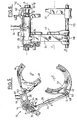
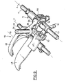
- FIGS. 1 to 3 show means for interconnection 10 for actuating the fork 42 of control of the first and second forward gears and of the fifth and sixth command range 44 forward gears that are both associated with the shaft secondary axis C of the gearbox according to the invention.
- the primary shaft carries all the fixed gears of the box, and the secondary trees all bear the crazy gears of the box, to determine different reports of reduction.
- control range 44 of the fifth and sixth forward gears, and the control range 42 of the first and second forward gears associated with secondary shaft C axis are intended to control the axial displacement along the C axis of two double claws partners (not represented), each intended to the commitment of two gear reduction reports before.
- a first dog double, controlled by the control fork 44 fifth and sixth forward gears is including movable axially between a neutral position and two positions opposite of interconnection crazy gears associated with soon fifth and sixth forward gears
- a second double clutch, controlled by the 42 command fork of first and second forward gears is including movable axially between a neutral position and two positions opposite of interconnection crazy gears associated with first and second forward gears.
- the actuator 12 can be connected by a linkage to the shift lever of the vehicle on which the driver acts, or, in a preferred embodiment of the invention, to be a roto-linear actuator by stepping motors, controlled in response to movements of a vehicle shift lever on which the driver acts.
- the box is an automated control gearbox, better known as the term "robotic box”.
- the finger 16 of the actuator 12 which extends radially to from the axial rod 14 of the actuator, is susceptible, at during its rotational movement, to cooperate selectively with contact ends of feet 34 and 36 transverse actuating respective forks 42 and 44 to perform selecting the two pairs of transmission ratios the boxes each associated with a range 42 or 44.
- each contact end of the feet 34 and 36 crosswise has an associated contact fork 26 and 28 which is capable of receiving the radial finger 16 of the actuator 12.
- each fork of contact 26, 28 consists of a U-shaped light which is cut into a plate that forms the transverse foot actuating 34, 36 associated with each fork.
- the actuator 12 can then be moved in sliding along its axis A in one direction or the other of in order to engage the transmission ratio chosen by the driver of the vehicle.
- the actuator comprises locking means of each transverse foot 42 or 44 which are intended, when the finger 16 of the actuator 12 is received in a contact fork 26 or 28 of a foot 34 or 36 associated with lock the other foot 36 or 34, to prevent two transmission reports are initiated simultaneously, which would cause the damage, even the destruction of the box of speeds.
- the range 44 of control of the fifth and sixth forward gears and the control range 42 of the first and second ratios of forward movement are mounted on a guide shaft 50 common axis D parallel to the C axis associated with the secondary shaft.
- the shaft 50 is slidably mounted in housings (no represented) of the box, and it passes through holes 136 and 138 ranges 44 and 42, as shown in FIG. fork 44 is slidably mounted on the shaft 50 and the fork 42 is fixedly mounted on the shaft 50, for example by via a radial pin 37 which passes radially the fork 42 and the axis 50.
- the two forks 42 and 44 are movable axially, the fork 44 sliding on the axis 50, and the fork 42 sliding along the axis D relative to the housings of the box when the shaft 50 is slidably actuated.
- the radial finger 16 of the actuator 12 is contained in a transverse plane which, in the rest position of the two forks 42 and 44, coincides with the plane of the dog of the fork 44 of control of the fifth and sixth forward gears.
- the control range 42 of the first and second forward gears is axially farther away of the actuator control finger that the fork 44 of control of the fifth and sixth forward gears.
- control finger 16 of the actuator should, to move from a selection position of the fork 42 at a selection position of the range 44, move at least the axial distance separating the range 44 of the range 42.
- the invention proposes a design to prevent that the rod 14 of the actuator 12 is subject to significant axial and radial deflections when actuated in sliding of the control range 42 of the first and second forward gears.
- each foot 34 or 36 function as a rocking lever which allows return the sliding movement of the radial finger 16 of the actuator 12 parallel to the axis C of the actuator 12.
- the first 34 and second 36 respective actuating feet of the command range 42 of the first and second report forward movement and the control fork 44 of the fifth and sixth forward report present respectively the shape of a first plate 36 and a second plate 34 which are contiguous to one another, and which are likely to slide over each other in a plane that is perpendicular to the axis F of their common pivot 140 when they are operated.
- the end of the first plate 36 comprises the first contact fork 28 in the form of light, and the end of contact of the second plate 34 has the second fork 26 of contact in the form of light.
- control ends 142 and 144 of the plates 36 and 34 which are located opposite the ends of contact 28 and 26 of the plates 36 and 34, on the other side of the pivot 140, each comprise a light 56, 54 which is cut out following an inverted U shape.
- the lights 56, 54 of the control ends 142 and 144 receive between their branches of cylindrical studs 60 and 58 corresponding, each transverse axis parallel to the axis F, which make it possible to drive the associated range 44 or 42.
- FIGS. 3 and 7 there is shown a light 54 which receives the cylindrical stud 58 for driving the fork 42 which extends radially from the guide shaft 50 of forks to bind and articulate the control fork 42 first and second forward gears in relation to the foot 34.
- a training pad 60 represented in FIGS. 3 and 8, belonging to the fork 44, extends directly from the fork 44, to bind and articulate the control range 44 of the fifth and sixth forward gears relative to the foot 36.
- the range 44 of control of the fifth and sixth forward gears can advantageously comprise a recess 152 which allows lay bare part of the tree 50 and allow the passage of the pad 58 which articulates the second plate 34 on the guide shaft 50 for controlling the control range 42 of the first and second forward gears.
- the recess 152 opens into the piercing 136 of the fork 44, so that a part of the shaft 50 which carries pad 58 is discovered.
- the stud 58 is mobile in sliding between transverse edges 154 of the recess 152 over its entire axial stroke of actuation of the fork 42 control of the first and second forward gears
- the foot 34 pivots around the axis pivot F and pushes in the opposite direction the stud 58 secured to the shaft 50 thereby actuating the fork 42.
- the plates 34 and 36 are offset transversely along the axis F, that is to say that the second plate 34 is transversely further from the forks 42, 44 that the first plate 36.
- the second plate 34 is longer than the first plate 36.
- This arrangement is advantageous because it allows, while along the axial races of the forks 42 and 44, at the ends 142 and 144 control plates slip on top of each other without creating interference between the plates 34 and 36.
- the ends 142 and 144 of the plates 34 and 36 have for trajectory two concentric circle arcs that are shifted one by relation to each other in two parallel planes perpendicular to axis F.
- the offset of the plates 34 and 36 along the axis F and their different lengths allow the selection of plates 34 and 36 through a simple rotational movement of the radial finger 16 of the actuator 12.
- the plate 36 is arranged in the extension of a radius of the actuator 12, and that the fork of contact 32 of the plate 34 is folded towards the actuator 12 so as to be arranged in the extension of a radius of the actuator 12, so as to allow easy selection plates 34 and 36 by the radial finger 16 of the actuator 12.
- first plate 36 and the second plate 34 advantageously comprise means for indexing a plate relative to each other, which are constituted for example an elastic tab 158 which extends on the face of the first plate 36 which is turned towards the plate 34, and which is susceptible to cooperate with an opening 156 of the second plate 34 when one or the other of the plates 34 or 36 is actuated in rotation to axially move the associated fork 42 or 44.
- Such interconnection means 10 make it possible to to dispense with a plurality of actuating cylinders of the type of those found in robotic gearboxes conventional, which makes it possible to have a box of robotic speeds to a single actuator 16 reacting more faster than a conventional robotic gearbox, this which makes it, again, particularly suitable for driving athletic.
Landscapes
- Engineering & Computer Science (AREA)
- General Engineering & Computer Science (AREA)
- Mechanical Engineering (AREA)
- Gear-Shifting Mechanisms (AREA)
Description
- la boíte comporte, sur un premier arbre secondaire, un crabot simple qui est agencé à proximité d'un pignon fou et qui est susceptible d'occuper sélectivement une position neutre ou une position de crabotage du dit pignon fou correspondant à l'engagement d'un rapport de démultiplication, et en ce que les autres crabots sont agencés entre deux pignons fous, pour occuper une position neutre ou deux positions opposées de crabotage de chacun des dits pignons fous, situées axialement de part et d'autre de la position neutre et correspondant chacune à l'engagement d'un rapport de démultiplication ;
- la tige de l'actionneur peut occuper plusieurs positions angulaires prédéfinies de sélection, qui correspondent chacune à la sélection d'une fourche par un doigt, et au moins une position axiale extrême de passage d'un des rapports de démultiplication et une position neutre ;
- les deux doigts radiaux coplanaires sont répartis angulairement dans leur plan commun de façon que, dans une position angulaire prédéfinie de sélection, un seul doigt soit reçu dans une fourche de contact déterminée, l'autre doigt n'étant reçu dans aucune fourche de contact ;
- la tige de l'actionneur porte une douille de verrouillage d'au moins un rapport non sélectionné, qu'elle entraíne seulement en rotation, par rapport à laquelle les doigts radiaux peuvent coulisser librement, et la douille comporte au moins une touche radiale, qui est interposée angulairement entre les doigts dans le plan commun des doigts et qui est destinée, dans la position angulaire prédéfinie de sélection d'une fourche par le doigt correspondant, à être reçue dans au moins une fourche associée à la dite au moins une fourchette non sélectionnée pour la verrouiller axialement ;
- le premier arbre secondaire comporte un crabot double associé à des troisième et quatrième rapports de marche avant et un crabot simple associé à un rapport de marche arrière, et
- le deuxième arbre secondaire comporte un crabot double associé à des premier et deuxième rapports de marche avant et un crabot double associé à des cinquième et sixième rapports de marche avant ;
- les fourchettes associées aux arbres secondaires sont montées par paires sur un arbre commun longitudinal de guidage ;
- la fourchette de commande des troisième et quatrième rapports de marche avant et la fourchette de commande du rapport de marche arrière sont montées coulissantes sur l'arbre de guidage commun fixe associé au premier arbre secondaire ;
- les pieds d'actionnement de la fourchette de commande des troisième et quatrième rapports de marche avant et de la fourchette de commande du rapport de marche arrière sont liés rigidement aux fourchettes associées ;
- la fourchette de commande des premier et deuxième rapports de marche avant et la fourchette de commande des cinquième et sixième rapports de marche avant sont montées respectivement fixe et coulissante sur l'arbre de guidage commun coulissant associé au deuxième arbre secondaire ;
- les pieds d'actionnement de la fourchette de commande des premier et deuxième rapports de marche avant et de la fourchette de commande des cinquième et sixième rapports de marche avant sont articulés en leur milieu, par un pivot d'axe transversal qui est porté par un carter de la boíte transversale par rapport à la direction axiale des arbres primaire et secondaire, sur un carter de la boíte ;
- la fourchette de commande des premier et deuxième rapports de marche avant est plus éloignée axialement du doigt de commande de l'actionneur que la fourchette de commande des cinquième et sixième rapports de marche avant ;
- un premier pied transversal, associé à la fourchette de commande des cinquième et sixième rapports de marche avant, et un deuxième pied transversal, associé à la fourchette de commande des premier et deuxième rapports de marche avant, présentent respectivement la forme d'une première et d'une deuxième plaques qui sont accolées l'une à l'autre dans un plan perpendiculaire à l'axe de leur pivot commun, une extrémité de commande de chaque plaque opposée à la fourche comportant une lumière découpée en forme de U inversé entre les branches de laquelle est reçu un plot cylindrique d'axe transversal d'entraínement de la fourchette associée, le plot d'entraínement de la fourchette de commande des premier et deuxième rapports de marche avant et le plot d'entraínement de la fourchette de commande des cinquième et sixième rapports de marche avant s'étendant respectivement à partir de l'arbre de guidage commun et de la fourchette de commande des cinquième et sixième rapports de marche avant, pour lier et articuler les fourchettes par rapport aux pieds ;
- la deuxième plaque est transversalement plus éloignée des fourchettes que la première plaque pour permettre la sélection des plaques par le doigt radial de l'actionneur ;
- la deuxième plaque est plus longue que la première plaque, pour permettre la sélection des plaques par le doigt radial de l'actionneur ;
- la fourche de contact de chaque plaque comporte une lumière qui est découpée en forme de U ;
- chaque plaque est susceptible d'être verrouillée par la tranche radiale de la douille de l'actionneur lorsque le doigt de l'actionneur est reçu dans la fourche de contact de l'autre plaque, et des moyens d'indexation sont interposés entre les première et deuxième plaques ;
- la boíte est à commande robotisée, et la tige de l'actionneur est solidaire d'un vérin roto-linéaire mû par des moteurs pas à pas, commandés en réponse à des mouvements d'un levier de changement de vitesses du véhicule sur lequel agit le conducteur ;
- la boíte est commandée manuellement et l'actionneur est relié par une tringlerie à un levier de changement de vitesses du véhicule sur lequel agit le conducteur.
- la figure 1 est une vue en perspective de l'actionneur et des pieds d'actionnement de deux fourchettes de commande de deux crabots d'un même arbre d'une boíte de vitesses selon une partie de l'invention ;
- la figure 2 est une vue en coupe, perpendiculaire à l'axe de l'actionneur et des pieds de commande des fourchettes de la boíte de vitesses selon l'invention ;
- la figure 3 est une vue de côté de l'actionneur et des pieds de commande des fourchettes de la boíte de vitesses selon une partie de l'invention ;
- la figure 4 est une vue en coupe, suivant l'axe de l'actionneur, de moyens de crabotage comportant un seul doigt de commande des fourchettes d'une boíte de vitesses selon un état antérieur de la technique ;
- la figure 5 est une vue en coupe suivant l'axe de l'actionneur de moyens de crabotage comportant deux doigts de commande des fourchettes d'une boíte de vitesses selon l'invention ;
- la figure 6 est une vue de côté des moyens de crabotage selon la figure 5 ;
- la figure 7 est une vue en perspective des moyens de crabotage de la boíte de vitesses selon une partie de l'invention, représentée du côté des pieds de fourchette des premier, second, cinquième et sixième rapports de marche avant, dans laquelle l'une des fourchettes est illustrée dans sa position de sélection d'un rapport ;
- la figure 8 est une vue de détail en perspective de la liaison du pied de la fourchette de commande des cinquième et sixième rapport de marche avant à la fourchette considérée ;
- la figure 9 est une vue en perspective des moyens de crabotage de la boíte de vitesses selon une autre partie de l'invention, représentée du côté des pieds de fourchette des troisième et quatrième rapports de marches avant et du rapport de marche arrière, dans laquelle l'une des fourchettes est illustrée dans sa position de sélection d'un rapport ;
- les figures 10 à 13 sont des vues suivant l'axe de l'actionneur représentant les moyens de crabotage en positions de sélection respectives des premier et deuxième rapports de marche avant, des cinquième et sixième rapports de marche avant, et du rapport de marche arrière.
Claims (19)
- Boíte de vitesses pour véhicule automobile, du type qui comporte un arbre primaire et deux arbres secondaires parallèles, du type qui comporte au moins trois engrenages dans chacun desquels un pignon fixe de l'arbre primaire engrène avec un pignon fou porté par chacun des arbres secondaires, du type qui comporte des moyens (10) de crabotage de chaque pignon fou sur l'arbre secondaire associé qui comportent des crabots associés à chaque pignon fou qui sont mobiles axialement sous l'action de moyens de commande comportant une fourchette (42, 44, 46, 48) de commande de chaque crabot qui est montée coulissante parallèlement à l'arbre secondaire associé et qui est munie d'un pied transversal (34, 36, 38, 40) d'actionnement lié à la fourchette (42, 44, 46, 48) de commande et mû par un actionneur (12), commun aux moyens de crabotage des deux arbres, dont une tige (14), commandée en translation axiale en coulissement est susceptible de déplacer sélectivement le pied (34, 36, 38, 40) d'actionnement de chaque fourchette (42, 44, 46, 48) pour engager un rapport de démultiplication correspondant, et est montée tournante par rapport à son axe (A),
caractérisée en ce que la tige (14) de l'actionneur (12) porte deux doigts radiaux (16, 17) transversalement coplanaires qui sont susceptibles, lorsque la tige (14) est commandée en rotation, d'être reçus dans des fourches (26, 28, 30, 32) de contact dont chacune est portée par l'extrémité libre d'un pied transversal (34, 36, 38, 40) de fourchette (42, 44, 46, 48), pour sélectionner au moins deux rapports de démultiplication associés chacun à un arbre secondaire déterminé en amenant chacun des doigts radiaux (16, 17) dans une fourche (26, 28, 30, 32) de contact déterminée correspondante, puis permettre d'engager un rapport sélectionné par commande en translation axiale de la tige (14). - Boíte de vitesses selon la revendication 1, caractérisée en ce qu'elle comporte, sur un premier arbre secondaire, un crabot simple qui est agencé à proximité d'un pignon fou et qui est susceptible d'occuper sélectivement une position neutre ou une position de crabotage du dit pignon fou correspondant à l'engagement d'un rapport de démultiplication, et en ce que les autres crabots sont agencés entre deux pignons fous, pour occuper une position neutre ou deux positions opposées de crabotage de chacun des dits pignons fous, situées axialement de part et d'autre de la position neutre et correspondant chacune à l'engagement d'un rapport de démultiplication.
- Boíte de vitesses selon la revendication 2, caractérisée en ce que la tige (14) de l'actionneur (12) peut occuper plusieurs positions angulaires prédéfinies de sélection, qui correspondent chacune à la sélection d'une fourche (26, 28, 30, 32) par un doigt (16, 17), et au moins une position axiale extrême de passage d'un des rapports de démultiplication et une position neutre.
- Boíte de vitesses selon la revendication précédente, caractérisée en ce que les deux doigts (16, 17) radiaux coplanaires sont répartis angulairement dans leur plan commun de façon que, dans une position angulaire prédéfinie de sélection, un seul doigt (16, 17) soit reçu dans une fourche (26, 28, 30, 32) de contact déterminée, l'autre doigt (17, 16) n'étant reçu dans aucune fourche (26, 28, 30, 32) de contact.
- Boíte de vitesses selon la revendication précédente, caractérisée en ce que la tige (14) de l'actionneur (12) porte une douille (22) de verrouillage d'au moins un rapport non sélectionné, qu'elle entraíne seulement en rotation, par rapport à laquelle les doigts radiaux (16, 17) peuvent coulisser librement, et en ce que la douille (22) comporte au moins une touche (24) radiale, qui est interposée angulairement entre les doigts (16, 17) dans le plan commun des doigts (16, 17) et qui est destinée, dans la position angulaire prédéfinie de sélection d'une fourche (26, 28, 30, 32) par le doigt (16, 17) correspondant, à être reçue dans au moins une fourche (26, 28, 30, 32) associée à la dite au moins une fourchette (42, 44, 46, 48) non sélectionnée pour la verrouiller axialement.
- Boíte de vitesses selon l'une quelconque des revendications 3 à 5, caractérisée en ce quele premier arbre secondaire comporte un crabot double associé à des troisième et quatrième rapports de marche avant et un crabot simple associé à un rapport de marche arrière, etle deuxième arbre secondaire comporte un crabot double associé à des premier et deuxième rapports de marche avant et un crabot double associé à des cinquième et sixième rapports de marche avant.
- Boíte de vitesses selon l'une quelconque des revendications précédentes, caractérisée en ce que les fourchettes (42, 44, 46, 48) associées aux arbres secondaires sont montées par paires sur un arbre commun (50, 52) longitudinal de guidage.
- Boíte de vitesses selon la revendication 7 prise en combinaison avec la revendication 6, caractérisée en ce que la fourchette (46) de commande des troisième et quatrième rapports de marche avant et la fourchette de commande (48) du rapport de marche arrière sont montées coulissantes sur l'arbre (52) de guidage commun fixe associé au premier arbre secondaire.
- Boíte de vitesses selon la revendication 8, caractérisée en ce que ce que les pieds d'actionnement (38, 40) de la fourchette (46) de commande des troisième et quatrième rapports de marche avant et de la fourchette (48) de commande du rapport de marche arrière sont liés rigidement aux fourchettes (46, 48) associées.
- Boíte de vitesses selon la revendication 7 prise en combinaison avec la revendication 6, caractérisée en ce que la fourchette (42) de commande des premier et deuxième rapports de marche avant et la fourchette (44) de commande des cinquième et sixième rapports de marche avant sont montées respectivement fixe et coulissante sur l'arbre (50) de guidage commun coulissant associé au deuxième arbre secondaire.
- Boíte de vitesses selon la revendication 10, caractérisée en ce que ce que les pieds (34, 36) d'actionnement de la fourchette (42) de commande des premier et deuxième rapports de marche avant et de la fourchette (44) de commande des cinquième et sixième rapports de marche avant sont articulés en leur milieu, par un pivot (140) d'axe transversal (F) qui est porté par un carter de la boíte transversalement par rapport à la direction axiale des arbres primaire et secondaire, sur un carter de la boíte.
- Boíte de vitesses selon la revendication 10 ou 11, caractérisée en ce que la fourchette (42) de commande des premier et deuxième rapports de marche avant est plus éloignée axialement du doigt (16) de commande de l'actionneur (12) que la fourchette (44) de commande des cinquième et sixième rapports de marche avant.
- Boíte de vitesses selon la revendication 11 ou 12, caractérisée en ce qu'un premier pied (36) transversal, associé à la fourchette (44) de commande des cinquième et sixième rapports de marche avant, et un deuxième pied (34) transversal, associé à la fourchette (42) de commande des premier et deuxième rapports de marche avant, présentent respectivement la forme d'une première (36) et d'une deuxième (34) plaques qui sont accolées l'une à l'autre dans un plan perpendiculaire à l'axe (F) de leur pivot (140) commun, une extrémité de commande (142, 144) de chaque plaque (36, 34) opposée à la fourche comportant une lumière découpée en forme de U inversé entre les branches de laquelle est reçu un plot (58, 60) cylindrique d'axe transversal d'entraínement de la fourchette (42, 44) associée, le plot (58) d'entraínement de la fourchette (42) de commande des premier et deuxième rapports de marche avant et le plot (60) d'entraínement de la fourchette (44) de commande des cinquième et sixième rapports de marche avant s'étendant respectivement à partir de l'arbre (50) de guidage commun et de la fourchette (44) de commande des cinquième et sixième rapports de marche avant, pour lier et articuler les fourchettes (42, 44) par rapport aux pieds (34, 36).
- Boíte de vitesses selon la revendication 13, caractérisée en ce que la deuxième plaque (34) est transversalement plus éloignée des fourchettes (42, 44) que la première plaque (36) pour permettre la sélection des plaques (34, 36) par le doigt (16) radial de l'actionneur (12).
- Boíte de vitesses selon la revendication 13 ou 14, caractérisée en ce que la deuxième plaque (34) est plus longue que la première plaque (36), pour permettre la sélection des plaques (34, 36) par le doigt (16) radial de l'actionneur (12).
- Boíte de vitesses selon la revendication 13 à 15, caractérisée en ce que la fourche de contact (26, 28) de chaque plaque (34, 36) comporte une lumière qui est découpée en forme de U.
- Boíte de vitesses selon les revendications 12 à 16 en combinaison avec la revendication 5, caractérisée en ce que chaque plaque (34, 36) est susceptible d'être verrouillée par la tranche radiale de la douille (22) de l'actionneur (12) lorsque le doigt (16) de l'actionneur (12) est reçu dans la fourche (28, 26) de contact de l'autre plaque (36, 34), et en ce que des moyens d'indexation (156, 158) sont interposés entre les première (36) et deuxième (34) plaques.
- Boíte de vitesses selon l'une quelconque des revendications 14 à 17, caractérisée en ce qu'elle est à commande robotisée, et en ce que la tige (14) de l'actionneur (12) est solidaire d'un vérin roto-linéaire mû par des moteurs pas à pas, commandés en réponse à des mouvements d'un levier de changement de vitesses du véhicule sur lequel agit le conducteur.
- Boíte de vitesses selon l'une quelconque des revendications 14 à 17, caractérisée en ce qu'elle est commandée manuellement et en ce que l'actionneur (12) est relié par une tringlerie à un levier de changement de vitesses du véhicule sur lequel agit le conducteur.
Applications Claiming Priority (4)
| Application Number | Priority Date | Filing Date | Title |
|---|---|---|---|
| FR9909779A FR2797018B1 (fr) | 1999-07-28 | 1999-07-28 | Boite de vitesses compacte |
| FR9909780A FR2797019B1 (fr) | 1999-07-28 | 1999-07-28 | Boite de vitesses comportant des pieds basculants d'actionnement des fourchettes |
| FR9909780 | 1999-07-28 | ||
| FR9909779 | 1999-07-28 |
Publications (2)
| Publication Number | Publication Date |
|---|---|
| EP1072824A1 EP1072824A1 (fr) | 2001-01-31 |
| EP1072824B1 true EP1072824B1 (fr) | 2003-11-12 |
Family
ID=26235060
Family Applications (1)
| Application Number | Title | Priority Date | Filing Date |
|---|---|---|---|
| EP00402152A Expired - Lifetime EP1072824B1 (fr) | 1999-07-28 | 2000-07-27 | Boíte de vitesses compacte comportant des pieds basculants d'actionnement des fourchettes |
Country Status (3)
| Country | Link |
|---|---|
| EP (1) | EP1072824B1 (fr) |
| DE (1) | DE60006457T2 (fr) |
| ES (1) | ES2204469T3 (fr) |
Families Citing this family (4)
| Publication number | Priority date | Publication date | Assignee | Title |
|---|---|---|---|---|
| DE102004017374A1 (de) * | 2004-04-08 | 2005-11-24 | Zf Friedrichshafen Ag | Schalteinrichtung für ein Schaltgetriebe |
| FR2873776B1 (fr) * | 2004-07-30 | 2006-10-27 | Renault Sas | Dispositif de commande interne pour boite de vitesse a double embrayage et procede d'apprentissage des positions de selection des rapports |
| CN109356974B (zh) * | 2018-10-29 | 2020-05-22 | 长兴佰菲特机械有限公司 | 一种用于v型多缸空气动力发动机的齿轮箱 |
| EP3825582B1 (fr) * | 2019-11-20 | 2024-04-10 | Stellantis Europe S.p.A. | Système de fonctionnement d'une boîte de vitesses pour un véhicule à moteur |
Family Cites Families (6)
| Publication number | Priority date | Publication date | Assignee | Title |
|---|---|---|---|---|
| DE3001935C2 (de) | 1980-01-21 | 1982-09-16 | Ford-Werke Ag, 5000 Koeln | Schaltvorrichtung für ein Wechselgetriebe |
| FR2609138B1 (fr) | 1986-12-26 | 1989-11-10 | Renault | Procede et dispositif de commande automatique de changement de rapport de transmission pour un ensemble embrayage boite de vitesses |
| JP2874080B2 (ja) * | 1993-07-16 | 1999-03-24 | 三菱自動車エンジニアリング株式会社 | 変速機のシフト装置 |
| SE506066C2 (sv) * | 1996-02-28 | 1997-11-03 | Volvo Ab | Växlingsmekanism |
| DE19730778A1 (de) * | 1997-07-17 | 1999-01-21 | Steyr Daimler Puch Ag | Kombinierte Schaltvorrichtung für die Antriebseinheit eines Allradfahrzeuges |
| DE29814943U1 (de) * | 1998-02-13 | 1999-05-27 | Kochendörfer & Kiep Stanz- und Feinstanzwerk GmbH & Co. KG, 78467 Konstanz | Getriebe |
-
2000
- 2000-07-27 DE DE60006457T patent/DE60006457T2/de not_active Expired - Lifetime
- 2000-07-27 ES ES00402152T patent/ES2204469T3/es not_active Expired - Lifetime
- 2000-07-27 EP EP00402152A patent/EP1072824B1/fr not_active Expired - Lifetime
Also Published As
| Publication number | Publication date |
|---|---|
| EP1072824A1 (fr) | 2001-01-31 |
| ES2204469T3 (es) | 2004-05-01 |
| DE60006457T2 (de) | 2004-08-26 |
| DE60006457D1 (de) | 2003-12-18 |
Similar Documents
| Publication | Publication Date | Title |
|---|---|---|
| EP0293288B1 (fr) | Dispositif de commande d'une boîte de vitesses de véhicule automobile | |
| WO1999057463A1 (fr) | Boite de vitesses compacte | |
| EP1308651B1 (fr) | Boíte de vitesses à sélection masquée | |
| FR2803890A1 (fr) | Barillet de commande pour boite de vitesses et boite de vitesses equipees d'un tel barillet | |
| EP0501845B1 (fr) | Dispositif de commande d'une boîte de vitesses | |
| EP0488857A1 (fr) | Dispositif interne de commande de boîte de vitesses | |
| EP1072824A1 (fr) | Boíte de vitesses compacte comportant des pieds basculants d'actionnement des fourchettes | |
| EP0737827B1 (fr) | Commande interne de boíte de vitesses avec dispositif de rappel d'organes de sélection | |
| EP1072823B1 (fr) | Tambour sélecteur de vitesses pour boíte de vitesses multiples de véhicules automobiles | |
| EP1174647A1 (fr) | Boíte de vitesses comportant un dispositif de crabotage à échappement | |
| FR2797018A1 (fr) | Boite de vitesses compacte | |
| WO1996023995A1 (fr) | Dispositif de commande d'une boite de vitesse | |
| FR2844570A1 (fr) | Dispositif de selection et de passage de vitesses pour une boite de vitesse pilotee de vehicule automobile | |
| EP1643168B1 (fr) | Dispositif de commande d'une boîte de vitesses pour véhicules automobiles | |
| EP1508728A1 (fr) | Dispositf de changement de vitesse, ensemble et véhicule automobile correspondants | |
| FR2878596A1 (fr) | Dispositif de commande interne d'une boite de vitesses pilotee a simple embrayage de vehicule automobile | |
| FR2797019A1 (fr) | Boite de vitesses comportant des pieds basculants d'actionnement des fourchettes | |
| FR2947886A1 (fr) | Systeme de commande pour une boite de vitesses | |
| FR2819569A1 (fr) | Dispositif de commande interne d'une boite de vitesses pour vehicule automobile | |
| EP0699855B1 (fr) | Dispositif perfectionné de commande d'une boíte de vitesses de véhicule automobile | |
| FR2868144A1 (fr) | Systeme de commande interne de boite de vitesses | |
| FR2702263A1 (fr) | Dispositif de commande d'une boîte de vitesses. | |
| FR2879277A1 (fr) | Dispositif de commande de boite de vitesses transformant une grille incoherente en grille coherente. | |
| FR2947885A1 (fr) | Systeme de commande pour une boite de vitesses | |
| FR2585429A1 (fr) | Dispositif de commande de deux rapports d'une boite de vitesses et boite de vitesses en comportant application |
Legal Events
| Date | Code | Title | Description |
|---|---|---|---|
| PUAI | Public reference made under article 153(3) epc to a published international application that has entered the european phase |
Free format text: ORIGINAL CODE: 0009012 |
|
| AK | Designated contracting states |
Kind code of ref document: A1 Designated state(s): BE DE ES |
|
| AX | Request for extension of the european patent |
Free format text: AL;LT;LV;MK;RO;SI |
|
| 17P | Request for examination filed |
Effective date: 20010731 |
|
| AKX | Designation fees paid |
Free format text: AT BE CH LI |
|
| RBV | Designated contracting states (corrected) |
Designated state(s): BE DE ES |
|
| 17Q | First examination report despatched |
Effective date: 20020619 |
|
| RAP1 | Party data changed (applicant data changed or rights of an application transferred) |
Owner name: RENAULT S.A.S. |
|
| GRAH | Despatch of communication of intention to grant a patent |
Free format text: ORIGINAL CODE: EPIDOS IGRA |
|
| GRAH | Despatch of communication of intention to grant a patent |
Free format text: ORIGINAL CODE: EPIDOS IGRA |
|
| GRAA | (expected) grant |
Free format text: ORIGINAL CODE: 0009210 |
|
| AK | Designated contracting states |
Kind code of ref document: B1 Designated state(s): BE DE ES |
|
| REF | Corresponds to: |
Ref document number: 60006457 Country of ref document: DE Date of ref document: 20031218 Kind code of ref document: P |
|
| REG | Reference to a national code |
Ref country code: ES Ref legal event code: FG2A Ref document number: 2204469 Country of ref document: ES Kind code of ref document: T3 |
|
| PLBE | No opposition filed within time limit |
Free format text: ORIGINAL CODE: 0009261 |
|
| STAA | Information on the status of an ep patent application or granted ep patent |
Free format text: STATUS: NO OPPOSITION FILED WITHIN TIME LIMIT |
|
| 26N | No opposition filed |
Effective date: 20040813 |
|
| PGFP | Annual fee paid to national office [announced via postgrant information from national office to epo] |
Ref country code: DE Payment date: 20170724 Year of fee payment: 18 Ref country code: ES Payment date: 20170825 Year of fee payment: 18 |
|
| PGFP | Annual fee paid to national office [announced via postgrant information from national office to epo] |
Ref country code: BE Payment date: 20170719 Year of fee payment: 18 |
|
| REG | Reference to a national code |
Ref country code: DE Ref legal event code: R119 Ref document number: 60006457 Country of ref document: DE |
|
| REG | Reference to a national code |
Ref country code: BE Ref legal event code: MM Effective date: 20180731 |
|
| PG25 | Lapsed in a contracting state [announced via postgrant information from national office to epo] |
Ref country code: DE Free format text: LAPSE BECAUSE OF NON-PAYMENT OF DUE FEES Effective date: 20190201 |
|
| PG25 | Lapsed in a contracting state [announced via postgrant information from national office to epo] |
Ref country code: BE Free format text: LAPSE BECAUSE OF NON-PAYMENT OF DUE FEES Effective date: 20180731 |
|
| REG | Reference to a national code |
Ref country code: ES Ref legal event code: FD2A Effective date: 20190917 |
|
| PG25 | Lapsed in a contracting state [announced via postgrant information from national office to epo] |
Ref country code: ES Free format text: LAPSE BECAUSE OF NON-PAYMENT OF DUE FEES Effective date: 20180728 |