EP1072548A2 - Dispositif pour empiler des articles plats - Google Patents
Dispositif pour empiler des articles plats Download PDFInfo
- Publication number
- EP1072548A2 EP1072548A2 EP00115706A EP00115706A EP1072548A2 EP 1072548 A2 EP1072548 A2 EP 1072548A2 EP 00115706 A EP00115706 A EP 00115706A EP 00115706 A EP00115706 A EP 00115706A EP 1072548 A2 EP1072548 A2 EP 1072548A2
- Authority
- EP
- European Patent Office
- Prior art keywords
- goods
- stacking
- transport
- speed
- run
- Prior art date
- Legal status (The legal status is an assumption and is not a legal conclusion. Google has not performed a legal analysis and makes no representation as to the accuracy of the status listed.)
- Granted
Links
Images


Classifications
-
- B—PERFORMING OPERATIONS; TRANSPORTING
- B65—CONVEYING; PACKING; STORING; HANDLING THIN OR FILAMENTARY MATERIAL
- B65H—HANDLING THIN OR FILAMENTARY MATERIAL, e.g. SHEETS, WEBS, CABLES
- B65H31/00—Pile receivers
- B65H31/24—Pile receivers multiple or compartmented, e.d. for alternate, programmed, or selective filling
-
- B—PERFORMING OPERATIONS; TRANSPORTING
- B65—CONVEYING; PACKING; STORING; HANDLING THIN OR FILAMENTARY MATERIAL
- B65H—HANDLING THIN OR FILAMENTARY MATERIAL, e.g. SHEETS, WEBS, CABLES
- B65H29/00—Delivering or advancing articles from machines; Advancing articles to or into piles
- B65H29/26—Delivering or advancing articles from machines; Advancing articles to or into piles by dropping the articles
- B65H29/30—Delivering or advancing articles from machines; Advancing articles to or into piles by dropping the articles from magnetic holders
-
- B—PERFORMING OPERATIONS; TRANSPORTING
- B65—CONVEYING; PACKING; STORING; HANDLING THIN OR FILAMENTARY MATERIAL
- B65H—HANDLING THIN OR FILAMENTARY MATERIAL, e.g. SHEETS, WEBS, CABLES
- B65H29/00—Delivering or advancing articles from machines; Advancing articles to or into piles
- B65H29/26—Delivering or advancing articles from machines; Advancing articles to or into piles by dropping the articles
- B65H29/32—Delivering or advancing articles from machines; Advancing articles to or into piles by dropping the articles from pneumatic, e.g. suction, carriers
-
- B—PERFORMING OPERATIONS; TRANSPORTING
- B65—CONVEYING; PACKING; STORING; HANDLING THIN OR FILAMENTARY MATERIAL
- B65H—HANDLING THIN OR FILAMENTARY MATERIAL, e.g. SHEETS, WEBS, CABLES
- B65H29/00—Delivering or advancing articles from machines; Advancing articles to or into piles
- B65H29/68—Reducing the speed of articles as they advance
-
- B—PERFORMING OPERATIONS; TRANSPORTING
- B65—CONVEYING; PACKING; STORING; HANDLING THIN OR FILAMENTARY MATERIAL
- B65H—HANDLING THIN OR FILAMENTARY MATERIAL, e.g. SHEETS, WEBS, CABLES
- B65H2406/00—Means using fluid
- B65H2406/30—Suction means
- B65H2406/32—Suction belts
- B65H2406/323—Overhead suction belt, i.e. holding material against gravity
-
- B—PERFORMING OPERATIONS; TRANSPORTING
- B65—CONVEYING; PACKING; STORING; HANDLING THIN OR FILAMENTARY MATERIAL
- B65H—HANDLING THIN OR FILAMENTARY MATERIAL, e.g. SHEETS, WEBS, CABLES
- B65H2511/00—Dimensions; Position; Numbers; Identification; Occurrences
- B65H2511/20—Location in space
-
- B—PERFORMING OPERATIONS; TRANSPORTING
- B65—CONVEYING; PACKING; STORING; HANDLING THIN OR FILAMENTARY MATERIAL
- B65H—HANDLING THIN OR FILAMENTARY MATERIAL, e.g. SHEETS, WEBS, CABLES
- B65H2513/00—Dynamic entities; Timing aspects
- B65H2513/20—Acceleration or deceleration
Definitions
- the invention relates to a device for stacking of flat goods, in particular from metal sheets to several stacking locations.
- Known devices are used for flat goods, for example, stacking printed metal sheets on top of each other, to, for example, one on a pallet To form stacks.
- To a production process it is known not to have to interrupt several Provide stacking locations so that the goods first to be placed on a stacking site then when the stack reaches a maximum height on the other stacking location without interruption to file.
- the second stacking location is loaded the stack of the first stacking location can be removed be, so that afterwards there again Goods can be deposited.
- the separation the goods are shipped to the first or second stacking location by means of switchable switches, that is mechanical devices are provided in the Goods transport route is located and - depending on the course - the delivery to the appropriate stacking location establish.
- the invention is therefore based on the object To create a device of the type mentioned at the outset, that with high flexibility and the greatest possible Protection of goods a precise and reproducible filing allowed. It is also advantageous if the device works quickly and precisely as well only a small construction volume or one short overall length required.
- the braking of the goods takes place by means of the transport storage device. Since this is designed as an overhead device and holds the corresponding material by means of a vacuum or magnetic field, a braking operation can be carried out in such a way that there is only a very small amount of material without a relative movement between the support surface of the transport and storage device and the material Speed or zero speed. It is therefore braked in a defined position. Once this has taken place, the vacuum that holds the good is switched off and the good can be placed on the stacking location without or with only an extremely low horizontal speed component.
- the goods are ferromagnetic goods
- a magnetic field to hold the goods on the transport storage device instead of the vacuum. Since the vacuum or the magnetic field can be switched, the device can be switched off at the moment the tablet is put down, so that the material is released and lowers at the storage location. After braking to the storage speed V 0 , the transport storage device is raised again to the transport speed V 1 in order to be able to take over the following goods. This means that braking and then acceleration are always carried out in alternating order. Due to the braking, edge damage, as can be the case in the prior art by bouncing off a stop, is prevented.
- the device according to the invention optionally provides a stop, which, however, essentially represents a guide for the vertical lowering of the good or — insofar as it is not braked completely to zero — forms a system against which the good runs at extremely low speed.
- the stop is suspended in an oscillating manner, so that it allows energy to be consumed without damaging the edges by slightly giving in. It is of particular importance that the braking process is carried out in relation to one of the stacking locations by means of a control device which works manually or automatically and the plate is then deposited there.
- braking is not carried out if the goods are passed over the stacking location and fed to the next or one of the other stacking locations, braked there and deposited there.
- This provides a high degree of flexibility, since the goods can be transferred to one or more stacking locations at the desired stacking location.
- the selection of the respective stacking location is possible, for example independently of the respective height of the stack. Of course, it is also possible in this way to ensure that a stack can be removed at a stacking location without causing an interruption in operation.
- the device according to the invention makes it possible to distribute the subsequent sheets to one or more other stacking locations, so that in the time available the stack that has reached its specific height is removed and by one Empty pallet can be replaced. It is then possible to go to this stacking location again.
- the goods holding device is a switchable Vacuum or switchable magnetic field for holding respectively Releases the goods.
- the Switching the vacuum on or off or of the magnetic field is also from the control device made so that both the braking or accelerate the transport storage device makes as well as holding respectively Releases the goods controls.
- the transport storage device is preceded by a transport device which has a rotating first strand.
- This first run is constructed in the manner of a conveyor belt, the goods resting on the upper run and thus being transported to the combined transport and storage device. It is envisaged that the goods on the first run will be held by gravity. The goods are therefore only on the upper run. This is possible without the relative movements between the crop and the strand, since the transport speed V 1 is constant. The run is thus operated at a constant speed.
- the transport storage device at least one rotating second Has strand and a circumferential third strand.
- Each of these two runs is assigned to a stacking location.
- more than two runs, ie a second, third, fourth, fifth, etc. strand are present that the transport storage facility form. Accordingly, there are many stacking locations intended.
- a bridging device transferring the goods is arranged between the second and the third run.
- This bridging device has the task, on the one hand, of transferring the goods from the second strand to the third strand without the front or back edge of the goods bending downwards, which, particularly at high speeds, can lead to a detachment of the table due to the air wedging air wedge .
- the bridging device thus ensures that the board remains essentially flat.
- the bridging device has the task of avoiding malfunctions which can occur in particular due to long designs.
- Each stacking location is preferably assigned its own overhead run, with a bridging device being arranged between the overhead runs of the stacking locations, which has a holding function on the goods and is either braked and accelerated, or else runs at a constant speed (transport speed V 1 ). If, for example, the overhead strand is braked at a stacking location in order to place a sheet of metal there, it must be accelerated again after the laying process. The greater the overall length of this overhead run, the longer this acceleration process will take. However, if overhead strands are used that have a relatively short overall length, which, for example, correspond to the largest possible sheet format, the inert masses are smaller and a corresponding quick braking and acceleration can be carried out. In order to close the gaps between these relatively short overhead strands, the bridging devices are provided.
- the second and the third strand one each separately for tax purposes has controllable servo motor drive.
- the servomotors can be optimally regulated or controlled, so that one extremely fast braking or acceleration of the associated dream is made possible. Because when braking the material on the run means Vacuum or magnetic field is held, it can Position it with high precision and then there lay down.
- the transport storage facility controllable push-off elements for the goods are assigned.
- the push-off elements serve the acceleration of the filing process as it -Afterwards the goods by means of the transport storage device the storage process has been slowed down by pressing down, i.e. removing the Accelerate good things from the transport and storage facility. Therefore, it is not only the gravitational force that works on the goods to be deposited, but this is supported by the push-off elements, so that that too under the goods to be deposited forming air cushions can escape faster.
- the transport storage device moving a good over a stacking place, when the goods are deposited on a subsequent one or several subsequent stacking locations respectively to a sampling device should be done. It is therefore the inventive Device for a series connection several stacking locations, with a good initially the stacking locations happen one after the other should not be started and then over the one The stacking location is slowed down and put down, the -According to a control algorithm of the plant- for that Layering is provided.
- every stacking location assigned its own transport storage facility the individual transport storage facilities can work independently.
- the invention further relates to a method for Layering of flat goods according to claim 11.
- Figure 1 shows a device 1 for stacking of flat goods 2 that are thin Metal sheets 3 are formed.
- the device 1 has a machine frame 4, the two boxes 5th and 6 includes that of stacking stacked Serve metal sheets 3.
- the Box 5 a stacking location 7 and Box 6 a stacking location 8th.
- the metal sheets 3 - coming from pre-processing - are supplied by means of a transport device 9.
- the direction of transport is indicated in FIG. 1 by means of arrow 10.
- the metal sheets 3 may have been painted, for example, so that they now have to be carefully stacked on top of one another without causing scratches and / or edge damage.
- the transport device 9 is designed as a first run 11 with a rotating conveyor belt 12, so that there is an upper run 13 and a lower run 14.
- the conveyor belt 12 is preferably divided into a plurality of individual belts which are spaced apart from one another and run over deflection rollers 15 and 16. By means of a not shown driving the conveyor belt 12 is operated at a constant transport speed V 1, so that on the upper run 13 lying Good 2 has pointing in the direction of transport 10 transporting speed V1.
- the transport device 9 is a transport storage device 17 - seen in the direction of transport 10 - which is a circumferential second strand 18 and a circumferential third strand 19. Between the second strand 18 and the third strand 19, a bridging device 20 is arranged. A sampling device is connected to the third strand 19 21 on.
- the second strand 18 has a conveyor belt 22 which of several, parallel, spaced apart Belt is formed which around pulleys 23 and 24 are performed.
- the bridging device 20 is formed by a strand 28, with a conveyor belt designed as a single belt 29 and pulleys 30 and 31.
- a suction box 32 of a goods holding device 57 Between the upper and the lower strand of the second strand 18 is located a suction box 32 of a goods holding device 57, the to a vacuum source, not shown a switching valve, not shown, is connected is. The same applies to the third Run 19.
- a suction box 33 of the goods holding device 57 provided, also over a switching valve on one or the same vacuum source connected. Finally, also points the bridging device 20 between top and Untertrum 28 on a suction box 34, the permanent is connected to one or the vacuum source.
- a servo motor drive 35 and also a servo motor drive on the deflection roller 26 36 connected the power transmission path from the respective servo motor drive to the associated one Deflection roller schematically by means of a Power transmission path 37 is indicated.
- the two servo motor drives 35 and 36 are more suitable Place fixed on the machine frame 4, so that the representation of Figure 1 only as is to be viewed schematically.
- Seen in the transport direction 10 follows the first run 11 the first storage location 7 in such a way that he was below the lower run of the second run 18 lies.
- the associated box 5 of this storage location 7 is from one adjacent to the first strand 11 Wall 40 and one in the direction of transport 10 seen at a distance from the limit stop 41.
- a Lift table 42 installed, the edition of the to forming stack of goods and depending from the stack height - by means of a not shown Device automatically lowered respectively can be driven up.
- the associated box 6 a wall 43, a stop 44 and a lifting table 45.
- the second strand 18 has a plurality of push-off elements 46 assigned as controllable piston / cylinder units 47 are formed. Is at rest the piston rod end 48 of each push-off element 46 at the level of the lower run of the second run 18 between the single belt.
- the third run is 19 also assigned push-off elements 46, however for simplicity and clarity in the Figure 1 are not shown.
- the servo motor drive In order to ensure a constant transfer of the sheet metal 2 from the transport device 9 to the second strand 18, the servo motor drive also moves the second strand 18 at the speed V 1 at the moment of the sheet transfer. As soon as the front edge of the metal sheet 3 approaches the stop 41, the servo motor drive 35 brakes the second strand 18 to a depositing speed V 0 , which is preferably zero, that is to say the second strand 18 is brought to a standstill. If this has taken place, the vacuum of the second run 18 is switched off by the suction box 32 being separated from the vacuum source by means of the valve (not shown). This separation can also take place if the end position of the metal sheet 3 described above has not yet been reached completely, since a residual holding force is still effective until the vacuum is completely released.
- V 0 depositing speed
- the push-off elements 46 come into action, that is to say the piston rod ends 48 press the metal sheet 3 off the lower run, so that it lies precisely on the already existing sheet metal stack. If the stack formed becomes too large, the lifting table 42 automatically lowers a little so that further metal sheets 3 can be accommodated there.
- the first run 18 will not carry out a braking operation, but will instead transport the metal sheet 3 further at the speed V 1 so that it reaches the third strand 19 via the bridging device 20.
- the bridging device 20 can have its own drive or can also be drive-free, so that only a holding force is exerted by the bridging device 20 on the metal sheet 3 due to the suction box 34.
- the arrangement is such that when the front edge of the metal sheet 3 approaches the third run 19, its servomotor drive 36 ensures that the third run 19 also has a speed V 1 , so that a continuous board transfer takes place without it Relative movements and thus damage can be carried out.
- the servo motor drive 36 is braked until - in the end position of the metal sheet 3- the standstill or almost the standstill is reached. Then, by switching off the vacuum, the sheet 3 is placed on the lifting table 45 or on the sheet 3 already lying there.
- Figure 1 shows that following the second Stacking location 8 arranged the sampling device 21 which is also an overhead device 49 is formed and has a strand 50 which is guided over pulleys 51 and 52. Between There is a suction box on the upper and lower run 53 connected to a vacuum source via a switching valve connected. Below the lower strand of the Sampling device 21 is located in Guides 54 running drawer 55, which - from the Drawing plane of Figure 1 are moved out can. It is possible by appropriate control a metal sheet 3 also over the second stacking location 8 lead away and the sampling device 21 hand over to the metal sheet 3 by means of a servo drive, not shown brakes accordingly and by switching off of the suction box 23 in the drawer 55. This can then be preferred by the user so that he can take samples and check the quality.
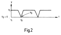
- FIG. 2 shows a diagram that illustrates the speed curve of the second run 18, for example.
- a speed V 1 is present at the time t 1 , that is to say the second run 18 moves at the transport speed V 1 .
- the operating state results Transit or the Filing operating state, the latter with a Intermittent operation by braking and accelerating connected is.
- the control device can preferably be designed such that an automatic Switching of the batch operation from one storage location to another is done as soon as the number the boards at a storage location a preselected or has reached the maximum possible number.
- the sampling device 21 can, as mentioned, discharge of boards for test purposes or the like serve, or it is also possible to get damaged or incorrect or incorrectly printed Discard boards so that they do not are first fed to the stacking locations. So should during the operational management by means of an automatic Detection can be demonstrated that one of the Panels has damage, so can from a removal is carried out in advance, with the two stacking locations not with such Waste is loaded. Because of overhead transportation and the possibility of the metal sheets 3 in a fixed position on the corresponding To hold the run and slow down the run it becomes possible to position the respective item precisely stop above the stacking tray and then with to form the corresponding stack with high accuracy.
- Figure 3 shows a further embodiment the invention, which is essentially the embodiment corresponds to Figure 1.
- On the 1 is therefore referred to.
- another Run 60 is located around two pulleys 61 and 62 is guided around and has a conveyor belt 63, that has an upper run 64 and a lower run 65.
- a gap 66 is formed through which the metal sheets 3 are passed through with the touch of the strand.
- the upper run 64 has a supporting function on the passing one Sheet 3, which prevents a metal sheet 3 from the bridging device 20 peels off.
- the direction of transport of the lower run 63 of the strand 60 is indicated by an arrow 67.
- the orbital speeds of bypass device 20 and run 60 are on top of each other coordinated and the same size, so no relative movement arises.
- the strand 60 can be a own drive assigned; however, it is also possible for the bridging device 20 and the strand 60 to use the same drive.
- Embodiment of the invention also be provided that instead of the run 60 one of compressed air device installed below is due to the resulting air cushion prevents a metal sheet 3 from peeling off can.
- the blowing device can, for example, as one or more compressed air strips formed his.
Landscapes
- Engineering & Computer Science (AREA)
- Mechanical Engineering (AREA)
- Stacking Of Articles And Auxiliary Devices (AREA)
Applications Claiming Priority (2)
| Application Number | Priority Date | Filing Date | Title |
|---|---|---|---|
| DE19935665 | 1999-07-29 | ||
| DE19935665A DE19935665B4 (de) | 1999-07-29 | 1999-07-29 | Vorrichtung zum Aufeinanderschichten von flächigen Gütern |
Publications (3)
| Publication Number | Publication Date |
|---|---|
| EP1072548A2 true EP1072548A2 (fr) | 2001-01-31 |
| EP1072548A3 EP1072548A3 (fr) | 2001-10-17 |
| EP1072548B1 EP1072548B1 (fr) | 2005-10-26 |
Family
ID=7916491
Family Applications (1)
| Application Number | Title | Priority Date | Filing Date |
|---|---|---|---|
| EP00115706A Expired - Lifetime EP1072548B1 (fr) | 1999-07-29 | 2000-07-21 | Dispositif et méthode pour empiler des articles plats |
Country Status (3)
| Country | Link |
|---|---|
| EP (1) | EP1072548B1 (fr) |
| DE (2) | DE19935665B4 (fr) |
| ES (1) | ES2251338T3 (fr) |
Cited By (11)
| Publication number | Priority date | Publication date | Assignee | Title |
|---|---|---|---|---|
| CH702716A2 (de) * | 2010-03-11 | 2011-09-15 | Ferag Ag | Steuervorrichtung und verfahren zur geschwindigkeitsregelung eines förderers. |
| US8505908B2 (en) | 2010-04-13 | 2013-08-13 | J&L Group International, Llc | Sheet deceleration apparatus and method |
| US9045243B2 (en) | 2011-08-04 | 2015-06-02 | J&L Group International, Llc | Apparatus and method for stacking corrugated sheet material |
| US9327920B2 (en) | 2011-12-28 | 2016-05-03 | Alliance Machine Systems International, Llc | Apparatus and method for stacking items |
| CN106800193A (zh) * | 2017-03-15 | 2017-06-06 | 东莞市瑞辉机械制造有限公司 | 一种自动化板件输送设备 |
| CN106892270A (zh) * | 2017-01-19 | 2017-06-27 | 广州宝钢井昌钢材配送有限公司 | 一种节能钢板堆垛稳定辅助装置 |
| CN106945982A (zh) * | 2016-01-07 | 2017-07-14 | 西班牙法格塞达公司 | 用于输送货物的输送设备和用于输送货物的方法 |
| EP2376356B1 (fr) * | 2009-01-09 | 2017-11-29 | Alliance Machine Systems International, LLC | Dispositif de freinage de feuilles, PROCÉDÉ POUR FREINER FEUILLES, ET EMPILEUR DE FEUILLES |
| CN108946181A (zh) * | 2018-08-22 | 2018-12-07 | 无锡市江南橡塑机械有限公司 | 胶片自动收片装置 |
| DE102017202748B4 (de) | 2017-02-21 | 2019-03-14 | Kba-Metalprint Gmbh | Verfahren und Vorrichtung zum Stapeln von flächigen Materialbogen sowie eine Druck- und/oder Lackiermaschine |
| US11161167B2 (en) | 2017-02-21 | 2021-11-02 | Koenig & Bauer Metalprint Gmbh | Method and device for stacking flat material sheets, and device and sheet metal printing machine for processing and/or treating material sheets in the form of metal sheets |
Families Citing this family (21)
| Publication number | Priority date | Publication date | Assignee | Title |
|---|---|---|---|---|
| DE10157098B4 (de) * | 2001-06-15 | 2005-07-14 | LTG Mailänder GmbH & Co. KG | Vorrichtung zum Transportieren und Stapeln von insbesondere tafelförmigen Gütern und entsprechendes Verfahren |
| ES2227364T3 (es) | 2001-06-15 | 2005-04-01 | Ltg Mailander Gmbh | Dispositivo para el transporte y apilado de procutos, especialmente en forma de planchas, y procedimiento correspondiente. |
| DE102004026612B4 (de) | 2004-06-01 | 2006-07-06 | Uhlmann Pac-Systeme Gmbh & Co. Kg. | Vorrichtung zur Stapelbildung von Packgut und Übergabe des Packgutstapels in ein Packguttransportsystem |
| DE102004057228A1 (de) * | 2004-11-26 | 2006-06-01 | Grenzebach Maschinenbau Gmbh | Verfahren und Vorrichtung zum Stapeln von auf einem Plattenförderer herangeführten Platten, insbesondere Glasplatten, mit hoher Geschwindigkeit |
| DE102007012814B3 (de) | 2007-03-16 | 2008-08-28 | Grenzebach Maschinenbau Gmbh | Vorrichtung zum automatischen Sortieren von Glasplatten |
| DE102007059916A1 (de) * | 2007-12-12 | 2009-06-18 | Koenig & Bauer Aktiengesellschaft | Bogendruckmaschine mit einem Ausleger |
| DE102008017753B4 (de) | 2008-04-07 | 2010-04-22 | Markus Eble | Transportvorrichtung zum Führen und Ablegen von Tafeln |
| DE202008004820U1 (de) | 2008-04-07 | 2008-08-21 | Eble, Markus | Transportvorrichtung zum Führen und Ablegen von Tafeln |
| CN101654199B (zh) * | 2009-07-30 | 2013-01-09 | 江苏华宇印涂设备集团有限公司 | 连续式收料装置 |
| DE102009042582A1 (de) * | 2009-09-24 | 2011-04-14 | Markus Eble | Transportsystem zum Führen und Ablegen von Tafeln aus Metall, Kunststoff oder Pappe |
| CN104692028B (zh) * | 2015-02-02 | 2017-04-05 | 电子科技大学 | 一种可选择真空吸附或电磁吸附的传送带吸附装置 |
| EP3271174B1 (fr) | 2015-06-29 | 2020-03-11 | Koenig & Bauer AG | Dispositif de sortie comprenant deux postes de distribution et procédé d'ajustement |
| WO2017001398A2 (fr) | 2015-06-29 | 2017-01-05 | Koenig & Bauer Ag | Dispositifs de sortie de feuilles, procédé de transport de feuilles, procédé de fonctionnement d'un dispositif de sortie de feuilles et procédé de commande d'une remise de feuilles d'étoffe imprimée |
| DE102016211623A1 (de) | 2015-06-29 | 2016-12-29 | Koenig & Bauer Ag | Auslageeinrichtung und Verfahren zum Betreiben einer Auslageeinrichtung |
| WO2017001395A2 (fr) | 2015-06-29 | 2017-01-05 | Koenig & Bauer Ag | Procédé permettant de faire fonctionner un dispositif de support de feuilles et dispositif de support pour une machine de traitement de feuilles |
| DE102015212072A1 (de) * | 2015-06-29 | 2016-12-29 | Koenig & Bauer Ag | Verfahren zum Betreiben einer Bremseinrichtung und eine Bogenleitvorrichtung für eine bogenverarbeitende Maschine |
| DE102016214970A1 (de) | 2016-08-11 | 2018-02-15 | Koenig & Bauer Ag | Auslagevorrichtung mit zumindest einer Abgabestation und ein Verfahren zur Auslage von Bedruckstoffbogen in einer Auslagevorrichtung |
| DE102016214977B4 (de) | 2016-08-11 | 2019-09-12 | Koenig & Bauer Ag | Verfahren zum Betreiben einer Auslagevorrichtung und eine Auslagevorrichtung einer Bogendruckmaschine |
| DE102016214972B4 (de) | 2016-08-11 | 2022-05-12 | Koenig & Bauer Ag | Auslagevorrichtung einer Bogendruckmaschine und ein Verfahren zur Auslage von Bedruckstoffbogen in einer Auslagevorrichtung |
| DE102016220921A1 (de) | 2016-10-25 | 2018-04-26 | Koenig & Bauer Ag | Auslagevorrichtung mit zumindest zwei Abgabestationen und Verfahren zur Auslage von Bedruckstoffbogen in einer Auslagevorrichtung mit zumindest zwei Abgabestationen |
| DE102017202749A1 (de) | 2017-02-21 | 2018-08-23 | Kba-Metalprint Gmbh | Verfahren und Vorrichtung zum Stapeln von flächigen Materialbogen sowie eine Druck- und/oder Lackiermaschine |
Citations (4)
| Publication number | Priority date | Publication date | Assignee | Title |
|---|---|---|---|---|
| GB921064A (en) * | 1959-10-08 | 1963-03-13 | Goebel Gmbh Maschf | Sheet-delivery device for a rotary printing press |
| DE2113239A1 (de) * | 1970-03-14 | 1971-09-23 | Nippon Yakin Kogyo Co Ltd | Vorrichtung zur Handhabung von Tafeln mit glatter Oberflaeche |
| US3907127A (en) * | 1973-12-13 | 1975-09-23 | Ppg Industries Inc | Apparatus for stacking sheet material |
| WO1993023185A1 (fr) * | 1992-05-20 | 1993-11-25 | Walker-Hagou B.V. | Methode de decoupage et d'empilage de toles __________ |
Family Cites Families (2)
| Publication number | Priority date | Publication date | Assignee | Title |
|---|---|---|---|---|
| DE3816756A1 (de) * | 1988-05-17 | 1989-11-30 | Baeumer Kg Spezialmasch | Stapelvorrichtung |
| DE19636160A1 (de) * | 1996-09-06 | 1998-03-12 | Nsm Magnettechnik Gmbh | Bandfördereinrichtung für die hängende Beförderung von Transportgütern mit Unterdruck |
-
1999
- 1999-07-29 DE DE19935665A patent/DE19935665B4/de not_active Expired - Fee Related
-
2000
- 2000-07-21 DE DE50011418T patent/DE50011418D1/de not_active Expired - Lifetime
- 2000-07-21 ES ES00115706T patent/ES2251338T3/es not_active Expired - Lifetime
- 2000-07-21 EP EP00115706A patent/EP1072548B1/fr not_active Expired - Lifetime
Patent Citations (4)
| Publication number | Priority date | Publication date | Assignee | Title |
|---|---|---|---|---|
| GB921064A (en) * | 1959-10-08 | 1963-03-13 | Goebel Gmbh Maschf | Sheet-delivery device for a rotary printing press |
| DE2113239A1 (de) * | 1970-03-14 | 1971-09-23 | Nippon Yakin Kogyo Co Ltd | Vorrichtung zur Handhabung von Tafeln mit glatter Oberflaeche |
| US3907127A (en) * | 1973-12-13 | 1975-09-23 | Ppg Industries Inc | Apparatus for stacking sheet material |
| WO1993023185A1 (fr) * | 1992-05-20 | 1993-11-25 | Walker-Hagou B.V. | Methode de decoupage et d'empilage de toles __________ |
Cited By (16)
| Publication number | Priority date | Publication date | Assignee | Title |
|---|---|---|---|---|
| EP2376356B1 (fr) * | 2009-01-09 | 2017-11-29 | Alliance Machine Systems International, LLC | Dispositif de freinage de feuilles, PROCÉDÉ POUR FREINER FEUILLES, ET EMPILEUR DE FEUILLES |
| CH702716A2 (de) * | 2010-03-11 | 2011-09-15 | Ferag Ag | Steuervorrichtung und verfahren zur geschwindigkeitsregelung eines förderers. |
| WO2011109916A1 (fr) * | 2010-03-11 | 2011-09-15 | Ferag Ag | Dispositif de commande et procédé pour réguler la vitesse d'un convoyeur |
| US9008834B2 (en) | 2010-03-11 | 2015-04-14 | Ferag Ag | Control device and method for controlling the speed of a conveyor |
| US8505908B2 (en) | 2010-04-13 | 2013-08-13 | J&L Group International, Llc | Sheet deceleration apparatus and method |
| US8827265B2 (en) | 2010-04-13 | 2014-09-09 | J&L Group International, Llc | Sheet deceleration apparatus and method |
| US9045243B2 (en) | 2011-08-04 | 2015-06-02 | J&L Group International, Llc | Apparatus and method for stacking corrugated sheet material |
| US9327920B2 (en) | 2011-12-28 | 2016-05-03 | Alliance Machine Systems International, Llc | Apparatus and method for stacking items |
| US9365369B2 (en) | 2011-12-28 | 2016-06-14 | Alliance Machine Systems International, Llc | Apparatus and method for stacking items |
| CN106945982A (zh) * | 2016-01-07 | 2017-07-14 | 西班牙法格塞达公司 | 用于输送货物的输送设备和用于输送货物的方法 |
| CN106945982B (zh) * | 2016-01-07 | 2020-09-29 | 西班牙法格塞达公司 | 用于输送货物的输送设备和用于输送货物的方法 |
| CN106892270A (zh) * | 2017-01-19 | 2017-06-27 | 广州宝钢井昌钢材配送有限公司 | 一种节能钢板堆垛稳定辅助装置 |
| US11161167B2 (en) | 2017-02-21 | 2021-11-02 | Koenig & Bauer Metalprint Gmbh | Method and device for stacking flat material sheets, and device and sheet metal printing machine for processing and/or treating material sheets in the form of metal sheets |
| DE102017202748B4 (de) | 2017-02-21 | 2019-03-14 | Kba-Metalprint Gmbh | Verfahren und Vorrichtung zum Stapeln von flächigen Materialbogen sowie eine Druck- und/oder Lackiermaschine |
| CN106800193A (zh) * | 2017-03-15 | 2017-06-06 | 东莞市瑞辉机械制造有限公司 | 一种自动化板件输送设备 |
| CN108946181A (zh) * | 2018-08-22 | 2018-12-07 | 无锡市江南橡塑机械有限公司 | 胶片自动收片装置 |
Also Published As
| Publication number | Publication date |
|---|---|
| EP1072548B1 (fr) | 2005-10-26 |
| DE50011418D1 (de) | 2005-12-01 |
| DE19935665B4 (de) | 2004-04-08 |
| EP1072548A3 (fr) | 2001-10-17 |
| DE19935665A1 (de) | 2001-03-01 |
| ES2251338T3 (es) | 2006-05-01 |
Similar Documents
| Publication | Publication Date | Title |
|---|---|---|
| DE19935665B4 (de) | Vorrichtung zum Aufeinanderschichten von flächigen Gütern | |
| DE69500305T2 (de) | Stapel-, Trennungs- und Abführungsstation für blattförmiges Gut, das von einer Verarbeitungsmaschine abgegeben wird | |
| DE1524522C3 (de) | Lochkartenmaschine | |
| DE4404017C2 (de) | Verfahren und Vorrichtung zum Palettieren von Stückgütern | |
| EP0718231A2 (fr) | Dispositif pour empiler des feuilles, en particulier pour des feuilles en papier ou carton qui sont alimentées en se chevauchant | |
| DE3702965A1 (de) | Einrichtung zum einlegen von zwischenlagen bei palettiermaschinen | |
| EP0575707B1 (fr) | Procédé pour le dépilage de feuilles uniques d'une pile de feuilles et son dispositif | |
| DE3015841C2 (fr) | ||
| EP3241791B1 (fr) | Procédé de fabrication d'empilements de feuilles | |
| WO1999008951A1 (fr) | Dispositif d'alimentation | |
| DE19911273C2 (de) | Verfahren und Vorrichtung zum Vereinzeln flächiger Güter | |
| WO1982000995A1 (fr) | Dispositif pour l'empilage de produits plans imbriques, en particulier de produits imprimes | |
| DE102005002532A1 (de) | Vorrichtung und Verfahren zum automatisierten und zeitgleichen Bereitstellen und Wechseln von mindestens zwei Rollen aus Papierbahnen oder dergleichen für einen nachgeordneten Formatschneider | |
| DE2819563A1 (de) | Vorrichtung zum stapeln und verblocken von kunststoffbeuteln | |
| EP1510489B1 (fr) | Procédé d'alimentation de feuilles de tôle plates imbriquées | |
| EP0698573A1 (fr) | Procédé et appareil pour alimenter des marchandises en feuilles | |
| DE2942254C2 (de) | Gruppiereinrichtung an einer Verpackungsmaschine | |
| EP0529204A1 (fr) | Appareil pour transférer des plaques vers une machine de thermoformage | |
| CH699389B1 (de) | Zwischenspeichervorrichtung und Stapeleinheit mit Zwischenspeichervorrichtung. | |
| CH719043A9 (de) | Vorrichtung zur Übergabe von Fördergütern zwischen zwei Fördervorrichtungen sowie ein Fördersystem und ein Übergabeverfahren. | |
| DE2558340C2 (de) | Vorrichtung zum Stapeln von blockförmigen Gütern | |
| EP1002755A2 (fr) | Dispositif pour séparer des cahiers de feullies d'une ligne de transport | |
| DE4210749C2 (de) | Vorrichtung zum Einbringen von Beutelpackungen in einen Sammelbehälter | |
| DE3614453C1 (en) | Transport apparatus | |
| DE3336067C2 (fr) |
Legal Events
| Date | Code | Title | Description |
|---|---|---|---|
| PUAI | Public reference made under article 153(3) epc to a published international application that has entered the european phase |
Free format text: ORIGINAL CODE: 0009012 |
|
| AK | Designated contracting states |
Kind code of ref document: A2 Designated state(s): AT BE CH CY DE DK ES FI FR GB GR IE IT LI LU MC NL PT SE Kind code of ref document: A2 Designated state(s): DE ES GB IT |
|
| AX | Request for extension of the european patent |
Free format text: AL;LT;LV;MK;RO;SI |
|
| PUAL | Search report despatched |
Free format text: ORIGINAL CODE: 0009013 |
|
| AK | Designated contracting states |
Kind code of ref document: A3 Designated state(s): AT BE CH CY DE DK ES FI FR GB GR IE IT LI LU MC NL PT SE |
|
| AX | Request for extension of the european patent |
Free format text: AL;LT;LV;MK;RO;SI |
|
| 17P | Request for examination filed |
Effective date: 20020417 |
|
| AKX | Designation fees paid |
Free format text: DE ES GB IT |
|
| RBV | Designated contracting states (corrected) |
Designated state(s): DE ES IT |
|
| 17Q | First examination report despatched |
Effective date: 20030701 |
|
| RTI1 | Title (correction) |
Free format text: DEVICE AND METHOD FOR STACKING FLAT GOODS |
|
| GRAP | Despatch of communication of intention to grant a patent |
Free format text: ORIGINAL CODE: EPIDOSNIGR1 |
|
| GRAS | Grant fee paid |
Free format text: ORIGINAL CODE: EPIDOSNIGR3 |
|
| GRAA | (expected) grant |
Free format text: ORIGINAL CODE: 0009210 |
|
| AK | Designated contracting states |
Kind code of ref document: B1 Designated state(s): DE ES IT |
|
| REF | Corresponds to: |
Ref document number: 50011418 Country of ref document: DE Date of ref document: 20051201 Kind code of ref document: P |
|
| REG | Reference to a national code |
Ref country code: ES Ref legal event code: FG2A Ref document number: 2251338 Country of ref document: ES Kind code of ref document: T3 |
|
| PLBE | No opposition filed within time limit |
Free format text: ORIGINAL CODE: 0009261 |
|
| STAA | Information on the status of an ep patent application or granted ep patent |
Free format text: STATUS: NO OPPOSITION FILED WITHIN TIME LIMIT |
|
| 26N | No opposition filed |
Effective date: 20060727 |
|
| REG | Reference to a national code |
Ref country code: DE Ref legal event code: R082 Ref document number: 50011418 Country of ref document: DE |
|
| REG | Reference to a national code |
Ref country code: DE Ref legal event code: R081 Ref document number: 50011418 Country of ref document: DE Owner name: KBA-METALPRINT GMBH, DE Free format text: FORMER OWNER: LTG MAILAENDER GMBH, 70435 STUTTGART, DE Effective date: 20120328 |
|
| REG | Reference to a national code |
Ref country code: ES Ref legal event code: PC2A Owner name: KBA-METALPRINT GMBH Effective date: 20120510 |
|
| PGFP | Annual fee paid to national office [announced via postgrant information from national office to epo] |
Ref country code: IT Payment date: 20190731 Year of fee payment: 20 Ref country code: DE Payment date: 20190827 Year of fee payment: 20 Ref country code: ES Payment date: 20190808 Year of fee payment: 20 |
|
| REG | Reference to a national code |
Ref country code: DE Ref legal event code: R071 Ref document number: 50011418 Country of ref document: DE |
|
| REG | Reference to a national code |
Ref country code: ES Ref legal event code: FD2A Effective date: 20201202 |
|
| PG25 | Lapsed in a contracting state [announced via postgrant information from national office to epo] |
Ref country code: ES Free format text: LAPSE BECAUSE OF EXPIRATION OF PROTECTION Effective date: 20200722 |