EP1070670A1 - Pompe à membrane et récipient ainsi équipé - Google Patents
Pompe à membrane et récipient ainsi équipé Download PDFInfo
- Publication number
- EP1070670A1 EP1070670A1 EP00401998A EP00401998A EP1070670A1 EP 1070670 A1 EP1070670 A1 EP 1070670A1 EP 00401998 A EP00401998 A EP 00401998A EP 00401998 A EP00401998 A EP 00401998A EP 1070670 A1 EP1070670 A1 EP 1070670A1
- Authority
- EP
- European Patent Office
- Prior art keywords
- membrane
- central
- pump according
- pumping chamber
- central duct
- Prior art date
- Legal status (The legal status is an assumption and is not a legal conclusion. Google has not performed a legal analysis and makes no representation as to the accuracy of the status listed.)
- Granted
Links
Images





Classifications
-
- B—PERFORMING OPERATIONS; TRANSPORTING
- B05—SPRAYING OR ATOMISING IN GENERAL; APPLYING FLUENT MATERIALS TO SURFACES, IN GENERAL
- B05B—SPRAYING APPARATUS; ATOMISING APPARATUS; NOZZLES
- B05B11/00—Single-unit hand-held apparatus in which flow of contents is produced by the muscular force of the operator at the moment of use
- B05B11/01—Single-unit hand-held apparatus in which flow of contents is produced by the muscular force of the operator at the moment of use characterised by the means producing the flow
- B05B11/10—Pump arrangements for transferring the contents from the container to a pump chamber by a sucking effect and forcing the contents out through the dispensing nozzle
- B05B11/1001—Piston pumps
- B05B11/1004—Piston pumps comprising a movable cylinder and a stationary piston
-
- B—PERFORMING OPERATIONS; TRANSPORTING
- B05—SPRAYING OR ATOMISING IN GENERAL; APPLYING FLUENT MATERIALS TO SURFACES, IN GENERAL
- B05B—SPRAYING APPARATUS; ATOMISING APPARATUS; NOZZLES
- B05B11/00—Single-unit hand-held apparatus in which flow of contents is produced by the muscular force of the operator at the moment of use
- B05B11/01—Single-unit hand-held apparatus in which flow of contents is produced by the muscular force of the operator at the moment of use characterised by the means producing the flow
- B05B11/10—Pump arrangements for transferring the contents from the container to a pump chamber by a sucking effect and forcing the contents out through the dispensing nozzle
- B05B11/1042—Components or details
- B05B11/1061—Pump priming means
-
- B—PERFORMING OPERATIONS; TRANSPORTING
- B05—SPRAYING OR ATOMISING IN GENERAL; APPLYING FLUENT MATERIALS TO SURFACES, IN GENERAL
- B05B—SPRAYING APPARATUS; ATOMISING APPARATUS; NOZZLES
- B05B11/00—Single-unit hand-held apparatus in which flow of contents is produced by the muscular force of the operator at the moment of use
- B05B11/01—Single-unit hand-held apparatus in which flow of contents is produced by the muscular force of the operator at the moment of use characterised by the means producing the flow
- B05B11/10—Pump arrangements for transferring the contents from the container to a pump chamber by a sucking effect and forcing the contents out through the dispensing nozzle
- B05B11/1042—Components or details
- B05B11/1064—Pump inlet and outlet valve elements integrally formed of a deformable material
-
- B—PERFORMING OPERATIONS; TRANSPORTING
- B05—SPRAYING OR ATOMISING IN GENERAL; APPLYING FLUENT MATERIALS TO SURFACES, IN GENERAL
- B05B—SPRAYING APPARATUS; ATOMISING APPARATUS; NOZZLES
- B05B11/00—Single-unit hand-held apparatus in which flow of contents is produced by the muscular force of the operator at the moment of use
- B05B11/01—Single-unit hand-held apparatus in which flow of contents is produced by the muscular force of the operator at the moment of use characterised by the means producing the flow
- B05B11/10—Pump arrangements for transferring the contents from the container to a pump chamber by a sucking effect and forcing the contents out through the dispensing nozzle
- B05B11/1042—Components or details
- B05B11/1073—Springs
- B05B11/1076—Traction springs, e.g. stretchable sleeve
-
- B—PERFORMING OPERATIONS; TRANSPORTING
- B05—SPRAYING OR ATOMISING IN GENERAL; APPLYING FLUENT MATERIALS TO SURFACES, IN GENERAL
- B05B—SPRAYING APPARATUS; ATOMISING APPARATUS; NOZZLES
- B05B11/00—Single-unit hand-held apparatus in which flow of contents is produced by the muscular force of the operator at the moment of use
- B05B11/0005—Components or details
- B05B11/0037—Containers
- B05B11/0039—Containers associated with means for compensating the pressure difference between the ambient pressure and the pressure inside the container, e.g. pressure relief means
- B05B11/0044—Containers associated with means for compensating the pressure difference between the ambient pressure and the pressure inside the container, e.g. pressure relief means compensating underpressure by ingress of atmospheric air into the container, i.e. with venting means
Definitions
- the present invention relates to a pump and a container containing a liquid, for example a cosmetic cream, equipped with such a pump.
- a pump comprising a push button mounted to move on a support subject to the container the product to be dispensed, the push button comprising a central cylindrical duct of revolution, provided with radial openings at its lower end, the support defining around this duct an annular pumping chamber, of volume variable.
- a membrane made of an elastomer is mounted on the support. This membrane has a symmetrical central part of revolution, in the form of sleeve open at its upper end and closed at its lower end. The central duct of the push button is inserted into the membrane until it takes press against the bottom of the sleeve. The membrane is a reminder elastic to return the push button to its initial position after the distribution of a dose of product.
- the diaphragm plate on the central duct isolates the pumping chamber from the radial openings of the central duct to avoid re-entry of air into the pumping chamber.
- Such a pump has the advantage of having only a small number of parts and therefore to be relatively inexpensive to manufacture.
- the present invention aims to improve the reliability of the operation of a pump of the type defined above, namely comprising a movable member mounted at displacement relative to a support, the movable member comprising a conduit central office into which the product to be distributed enters through at least one opening, the support defining with the movable member, around said central duct, a pumping chamber of variable volume, this pump further comprising a membrane having a central part into which said central duct is inserted, the membrane being arranged so as to isolate the pumping chamber from the or said openings of the central duct when the volume of the pumping chamber increases and that product is sucked into it.
- At least one of the central duct and the part central membrane has an annular boss capable of being applied from tightly, when the volume of the pumping chamber increases, on the other the central duct and the central part of the membrane, to isolate the pumping of the central duct opening (s).
- the aforementioned boss ensures closure of the annular passage formed around the central duct between the pumping chamber and the opening (s) of the central duct during the aspiration phase.
- the surface of the membrane which is applied to the central duct to ensure this closure is of small extent due to the presence of the boss, so that low air pressure in the pumping chamber can be enough to break the seal between the membrane and the central duct.
- the invention makes it possible to reduce to a certain extent the influence of the module elasticity of the material constituting the membrane on the operation of the pump, so use a harder elastomer to reduce the prestressing of the membrane while retaining the desired spring effect.
- the boss is made on the inner surface of the central part of the membrane.
- the boss thus produced on the central part of the membrane is applied tightly, at least when the volume of the pumping chamber increases, on the central duct to isolate the pumping chamber from the opening (s) of the central duct.
- the boss also applies at rest so waterproof on the central duct.
- the boss is produced on the external surface of the central duct.
- the boss When the boss is made on the inner surface of the membrane, advantageously produces on the central duct one or more reliefs in hollow or in projection, away from the boss when the movable member is in the high position and reaching the boss at the end of the driving part of the moving member, these reliefs being arranged to facilitate the creation at this time of a passage between the room pumping and the opening (s) of the central duct.
- This or these reliefs are for example in the form of one or more ribs formed on the outer surface of the central duct.
- the central part of the membrane comprises a bottom comprising an interior stud arranged to engage in the end bottom of the central duct.
- Such a pad ensures relatively stable maintenance of the end lower part of the central part of the membrane on the lower end of the duct central.
- the membrane has a flexible lip able, on the one hand, to isolate the pumping chamber from a source of product when the volume of said pumping chamber decreases and, on the other hand, to allow a re-entry of product into said pumping chamber when the volume of this last increases.
- this flexible lip is connected to the part central part of the membrane by forming an annular groove open downwards, and the support has an inner skirt bearing at its upper end in the bottom of said groove to retain the membrane when the movable member is moved down to decrease the volume of the pumping chamber.
- the aforementioned inner skirt has openings at its upper end whose height is less than that of the flexible lip, these openings allowing product to be drawn into the pumping chamber when the volume of the latter increases and the flexible lip moves away from the skirt interior.
- the central part of the membrane is connects at its upper end to an annular part whose width and the thickness are chosen so as to improve the maintenance of the membrane when said central part is stretched.
- the thickness of the abovementioned annular part, before mounting of the membrane in the pump is greater than or equal to the thickness of the membrane in its central part.
- the abovementioned annular part is, before mounting the membrane in the pump, at least 1.5 times wider than thick, and preferably 2 times wider than thick.
- one of the flexible lip and the inner skirt has a annular boss capable of being applied to the other of the flexible lip and of the skirt interior to isolate the pumping chamber from the interior of the container, when the volume of the pumping chamber decreases.
- the flexible lip has on its surface interior an annular boss capable of being applied in a sealed manner on the skirt interior to isolate the pumping chamber from the product source at least when the volume of the pumping chamber decreases.
- This annular boss advantageously applies at rest so waterproof on the inner skirt.
- the flexible lip advantageously comprises, above this boss annular, a preferential deformation zone preferably constituted by a thinned area.
- the inner skirt has a boss on its outer surface annular able to apply sealingly on the flexible lip to isolate the pumping chamber of the product source when the volume of the pumping decreases.
- the height of the aforementioned flexible lip is greater than or equal to the height of the central part of the membrane, before the mounting of the latter in the pump.
- the outer surface of the flexible lip has, in the vicinity of its upper end, a diverging conical portion when approaching the upper end of the membrane, this conical portion is connecting by a shoulder to an annular rib.
- the inside diameter of the flexible lip is equal to manufacturing tolerances, to the outside diameter of the inside skirt.
- the clearance between the flexible lip and the inner skirt is negative or zero; thus, the flexible lip is tightened slightly on the inner skirt.
- the length of the central part of the diaphragm, after mounting in the pump is greater than or equal to 1.5 times its initial length before mounting in the pump, even greater than or equal to 2 times said initial length, or even greater than or equal to 3 times said initial length.
- the length of the central part of the membrane is greater than or equal to 2 times the initial length of the membrane before mounting it on the pump, or even greater than or equal to 3 times said initial length, or even greater than or equal at 4 times said initial length.
- At least one of the membrane and the conduit central is shaped to prevent formation, between the membrane and the duct central, of a tight annular zone preventing the product contained in the room pumping to flow through the central duct when the volume of the chamber pumping decreases.
- At least one of the membrane and the central duct is shaped to bear against the other of the membrane and the central duct in predetermined locations on its periphery, at least during movement relative of the movable member and the support.
- At least one of the membrane and of the central duct comprises reliefs against which the other of the membrane and the conduit comes to bear central, at least during the relative movement of the movable member and the support.
- said reliefs are produced on the membrane in being preferably constituted by bosses equi-distributed around the axis of the central part of the membrane at its opening, these bosses preferably extending on the upper face of the membrane.
- the support has a double lip sealing, sealingly applied to a tubular skirt of the member mobile, this tubular skirt being open downwards and extending around the duct central concentrically to the latter, this tubular skirt further delimiting radially outwards the pumping chamber.
- the inner skirt of the support is part of an attachment on the rest of the support.
- the central duct of the movable member is provided at its lower end with at least one radial opening.
- the movable member constitutes a push button, the aforementioned central duct being made in one piece with a nozzle distribution.
- the tubular skirt of the movable member slides inside a support guide skirt, forming with the interior skirt of the supports an annular groove open upwards, communicating by at least one air return orifice with the source of product, the tubular skirt of the movable member applying sealingly on said guide skirt when the movable member is at rest and the volume of the pumping chamber is maximum.
- the membrane can be made of a nitrile elastomer or a silicone elastomer, for example, other materials which can of course be used.
- the invention also relates to a container equipped with a pump such as defined above.
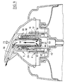
- FIG. 1 a container 1 having a body 2 forming reservoir, of which only the upper end can be seen in the drawing, defining a neck 3 on which a support is snapped 4.
- the support 4 guides in sliding, along an axis X, a push button 5 and used to mount a removable protective cover 6, covering the push button 5 before first use.
- the support 4 comprises a sealing skirt 7 which is applied so waterproof on the inside surface of the neck 3.
- the sealing skirt 7 is extended radially, on the one hand towards the outside by fixing lugs 8 snapped onto an annular bead 9 of the neck 3, and on the other hand inwards by a stepped wall 10 defining a nozzle 12 serving to the connection of a dip tube 13, partially shown in the drawing.
- An outer skirt 15 and a guide skirt 16 are made in one holding by plastic molding with the sealing skirt 7, the tabs fixing 8 and the stepped wall 10.
- the outer skirt 15 extends around the neck 3 of the container and has a shoulder 17 on which the protective cover 6 is supported.
- the upper edge 18 of the outer skirt 15 retains the push button 5 at rest, as will be explained below.
- the support 4 comprises an inner skirt 20 constituted by a part reported, having a shoulder lower end 21, forcibly engaged in the wall tier 10.
- the internal skirt 20 has a substantially tapered upper end, provided with openings 22, as can be seen more particularly in the figures 2 and 3.
- openings 22 are in the example described in the form of slots oriented along the X axis, extended downward by grooves 25 extending over the radially inner surface of the inner skirt 20 until a step 26.
- a double annular sealing lip 24 is made in one piece with the inner skirt 20 on the outer side of the latter by molding of material plastic.
- the push button 5 has an outer skirt 3U, provided with its lower end of teeth 31, the latter abutting against the edge upper 18 of the outer skirt 15 of the support 4 when the push button 5 is at rest in the high position, as shown in Figure 1.
- the push button 5 has a central duct 32, of axis X, and a skirt tubular 33 concentric, defining around the central duct 32 a pumping 34 annular.
- the outer skirt 30, the tubular skirt 33 and the central duct 32 are made in one piece by plastic molding with a tip distribution 35, communicating internally with the central duct 32.
- the latter has, at its lower end, radial openings 36.
- the lower end of the tubular skirt 33 forms a sealing lip 37, extending slightly radially outward, as shown more particularly in Figure 4.
- the guide skirt 16 of the support 4 has in the lower part a slight annular withdrawal 41 on its radially inner surface.
- the interior of the container is thus isolated from the ambient air, which is favorable to good conservation of the product.
- An air intake orifice 42 is made in the bottom of this groove to allow air to re-enter the container as it is emptied latest.
- the inner skirt 20 is used for mounting a membrane 50 having a part central unit 51 in the form of a sleeve, of axis X, open at its upper end and closed at its lower end by a bottom 52.
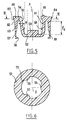
- This central part 51 is extended radially outwards by a flexible annular lip 53, as can be seen more particularly in the figure 5.
- This flexible lip 53 forms, by connecting with the central part 51, a annular groove 54 into which the inner skirt 20 is inserted at its end upper, until taking support by its free edge in the bottom of said groove.
- the flexible lip 53 is made so as to slightly tighten the skirt interior 20.
- the height of the flexible lip 53 is greater than that of the openings 22 and the flexible lip 53 is suitable for applying at rest in a sealed manner against the surface outside of the inner skirt 20, below the openings 22, as illustrated in the figure 1.
- the flexible lip 53 has at its lower end and on its radially inner surface an annular boss 56, of semi-circular section, able to be applied by its top line on the inner skirt 20 at rest.
- the flexible lip 53 has a thinner area 57 above of the boss 56, so as to facilitate the outward deformation of the part bottom of flexible lip 53 to allow boss 56 to move apart easily from the inner skirt 20 when the product contained in the container must win the pumping room.
- the outer surface of the flexible lip 53 has, from its end lower, a lower portion 81 substantially cylindrical of revolution around the X axis, then a conical upper portion 82 diverging upwards, this portion conical 82 connecting by a shoulder 83 to an annular rib 84.
- the membrane 50 comprises, at the opening of its central part 51, non-symmetrical reliefs of revolution around the X axis, namely in the example in particular bosses 55 whose function will be specified below.
- these bosses 55 are three in number, being evenly distributed angularly around the X axis, as we can see on the figure 6.
- Each of these bosses 55 protrudes from the radially inner surface of the central part 51 and extends radially outwards on the face upper part of the membrane 50 up to substantially above the groove 54.
- Each of the bosses 55 further presents, when observed in section in a transverse section plane, a convex section towards the X axis, as shown in the figure 6.
- the inner surface of the central part 51 of the membrane has a upper portion 70 slightly conical towards the bottom 52.
- the bosses 55 extend over this conical portion 70.
- the annular part 85 which joins the flexible lip 53 to the central part 51 is relatively wide and thick, which makes it possible to immobilize the end well upper part of the central part 51 relative to the inner skirt 20, when the part central 51 is stretched.
- the annular part 85 is approximately two times wider than thick, outside the bosses 55.
- the central part 51 of the membrane has on its inner surface a annular boss 58, of semicircular section.
- This boss 58 is intended to be applied by a generator on the surface outside of the central duct 32 above the openings 36, when the push-button goes up, in order to close the passage between the pumping chamber 34 and inside the central duct 32.
- the boss 58 has a radius of 0.25 mm, the thickness e of the wall constituting the central part 51 of the membrane being 0.55 mm.
- the bottom 52 of the central part 51 of the membrane has a stud 59 on its upper face, intended to engage in the lower end of the central duct 32.
- the central duct 32 is shown in broken lines in FIG. 5.
- the outside diameter of the pad 59 corresponds to the inside diameter of the conduit central 32.
- the stud 59 keeps the bottom 52 of the membrane fixed relative to the central duct 32.
- the length of the central part 51 of the membrane is approximately 3 times the initial length l 0 of the central part 51, that is to say that l elongation reaches 200%.
- the length l 0 measured between the bottom of the groove 54 and the upper face of the bottom 52 is approximately 3 mm and when the membrane is in place in the pump and the button pusher at rest as shown in FIG. 1, the length of the central part 51 is approximately 9 mm.
- the length of the central part 51 reaches an elongation of 350%.
- the length of the central part 51 is then, for the example considered, 13.5 mm, the stroke of the push button 5 down being 4.5 mm.
- the central duct 32 of the push button 5 is inserted into the central part 51 of the membrane 50 until it bears, by its end lower, against the bottom 52 of the membrane 50 around the stud 59, as illustrated on Figure 1.
- bosses 55 are then applied against the cylindrical surface of revolution of the central duct 32. However, it is not generally necessary that the bosses 55 are applied to the central duct 32 when the push button is resting.
- the double sealing lip 24 is applied sealingly to the surface radially inner of the tubular skirt 33, whatever the upward movement or down from push button 5.
- the boss 58 is applied by its apex to the central duct 32, which closes the passage between the pumping chamber 34 and the radial openings 36.
- the flexible lip 53 comes to rest at rest by the annular boss 56 on the inner skirt 20, which closes the passage between the pumping chamber 34 and inside the container.
- the central duct 32 advantageously comprises, as shown in the Figures 7 and 8, ribs 60 parallel to the axis X, whose lower ends 61 are distant from the annular boss 58, when the push button is in position high, by a distance corresponding to the push-in stroke.
- ribs 60 are optional, but facilitate priming of the pump. as explained below.
- the ribs 60 come into contact with the annular boss 58 at the end of the stroke. to push the push button to ensure that the annular boss 58 moves away well from the central duct 58, as illustrated in FIG. 12.
- the support 4, the push button 5 and the membrane 50 constitute a pump the operation of which is as follows.
- the central duct 32 drives down the bottom 52 of the membrane 50, which elastically deforms by stretching to accompany the movement down the central duct 32.
- the pump is here assumed to be primed, i.e. the pumping chamber 34 is filled with product.
- the product contained in the pumping chamber 34 is driven between the central duct 32 and the central part 51 of the membrane and reaches the radial openings 36 of the duct central 32, then the distribution nozzle 35.
- the flexible lip 53 is applied sealingly by the annular boss 56 on the inner skirt 20 during the downward movement of the push button 5.
- the sealing lip 37 of the tubular skirt 33 of the push button 5 ceases, when it reaches the annular withdrawal 41 after a certain driving stroke of the push button 5, to be applied in a sealed manner on the guide skirt 16, allowing communication between the inside of the container and the outside, by through the air intake orifice 42 and the clearance existing between the skirt guide 16 and the tubular skirt 33.
- the bosses 55 between them provide passages for the product and prevent the formation of a sealed annular zone between the central duct 32 and the central part 51 of the membrane 50 which could not be overcome by the pressure of the product, so that the product can flow to the radial openings 36, the annular boss 58 which can deviate slightly from the central duct 32 under the effect product pressure.
- the contact surface between the membrane 50 and the central duct 32 above radial openings 36 is due to the presence of the annular boss 58, relatively limited, which facilitates the creation of a passage to the openings radial 36.
- the bosses 55 tend to keep the central duct 32 coaxial with the skirt inner 20 and to guarantee the attachment of the membrane to the inner skirt 20.
- the annular boss 58 closes the passage between the radial openings 36 and the pumping chamber 34, and the depression created in the latter causes the flexible lip to move apart 53 of the inner skirt 20 and an arrival of product from the container.
- the product reaches the pumping chamber 34 by circulating through the grooves 25 of the inner skirt 20 along the central part 51 of the membrane 50, in crossing the inner skirt 20 in favor of the openings 22, then bypassing the flexible lip 53 and going up on the outside of the latter, as illustrated on the figure 10.
- bosses 55 can be replaced by the reliefs produced on the central duct.
- the annular boss 58 can be removed and replaced alternatively by a annular boss 58 'made on the outer surface of the central duct 32, above radial openings 36, as illustrated in FIG. 13.
- annular boss 56 can be removed as illustrated in FIG. 14 and replaced by an annular boss 56 ′ produced on the skirt interior 20, just below the openings 22, as shown in FIG. 15.
Landscapes
- Reciprocating Pumps (AREA)
- Closures For Containers (AREA)
- Diaphragms And Bellows (AREA)
- Display Devices Of Pinball Game Machines (AREA)
- Separation Using Semi-Permeable Membranes (AREA)
Abstract
Description
- la figure 1 est une vue schématique de la partie supérieure d'un récipient équipé d'une pompe conforme à l'invention,
- les figures 2 et 3 représentent isolément la jupe intérieure du support,
- la figure 4 représente isolément et partiellement, l'extrémité inférieure de la jupe tubulaire de l'organe mobile,
- la figure 5 représente isolément, en coupe axiale schématique, la membrane destinée à équiper la pompe de la figure 1, avant son montage dans la pompe,
- la figure 6 est une coupe selon le trait de coupe VI-VI de la figure 5,
- la figure 7 représente de façon partielle et schématique le conduit central,
- la figure 8 est une coupe transversale selon le trait de coupe VIII - XIII de la figure 7,
- la figure 9 illustre le fonctionnement de la pompe lorsque l'on appuie sur le bouton-poussoir,
- la figure 10 illustre le fonctionnement de la pompe lorsque l'on relâche le bouton-poussoir,
- les figures 11 et 12 illustrent l'action d'un relief du conduit central sur le bossage de la membrane,
- la figure 13 est une vue analogue à la figure 5, représentant une variante de réalisation de la membrane,
- la figure 14 représente partiellement une variante de réalisation de la lèvre flexible, et
- la figure 15 est une vue analogue à la figure 2, représentant une variante de réalisation de la jupe intérieure du support.
Claims (32)
- Pompe du type comportant un organe mobile monté à déplacement relativement à un support, l'organe mobile comportant un conduit central dans lequel le produit devant être distribué pénètre à la faveur d'au moins une ouverture, le support définissant avec l'organe mobile, autour dudit conduit central, une chambre de pompage de volume variable, cette pompe comportant en outre une membrane ayant une partie centrale dans laquelle est inséré ledit conduit central, la membrane étant agencée de manière à isoler la chambre de pompage de la ou desdites ouvertures du conduit central quand le volume de la chambre de pompage augmente et que du produit est aspiré dans cette dernière, pompe caractérisée par le fait que l'un au moins du conduit central (32) et de la partie centrale (51) de la membrane comporte un bossage annulaire (58 ; 58') apte à s'appliquer de manière étanche, lorsque le volume de la chambre de pompage (34) augmente, sur l'autre du conduit central et de la partie centrale de la membrane, pour isoler la chambre de pompage (34) de la ou des ouvertures (36) du conduit central (32).
- Pompe selon la revendication 1, caractérisée par le fait que la partie centrale de la membrane (51) comporte un bossage annulaire (58) s'appliquant de manière étanche, au repos et lorsque le volume de la chambre de pompage augmente, sur le conduit central (32) pour isoler la chambre de pompage (34) de la ou des ouvertures (36) du conduit central (32)
- Pompe selon la revendication précédente, caractérisée par le fait que le conduit central (32) comporte un ou plusieurs reliefs (60) en creux ou en saillie, éloignés dudit bossage (58) lorsque l'organe mobile est en position haute et atteignant le bossage (58) en fin de course d'enfoncement de l'organe mobile, ces reliefs étant agencés de manière à faciliter la création à ce moment d'un passage entre la chambre de pompage (34) et la ou les ouvertures (36) du conduit central (32).
- Pompe selon la revendication précédente, caractérisée par le fait que le ou lesdits reliefs se présentent sous la forme d'une ou plusieurs nervures (60) réalisées sur la surface extérieure du conduit central (32).
- Pompe selon la revendication précédente, caractérisée par le fait que la partie centrale de la membrane comporte un fond comprenant un plot intérieur (59) agencé pour s'engager dans l'extrémité inférieure du conduit central (32).
- Pompe selon l'une quelconque des revendications précédentes, caractérisée par le fait que la membrane comporte une lèvre flexible (53) apte, d'une part à isoler la chambre de pompage (34) de la source de produit quand le volume de ladite chambre de pompage (34) diminue, et d'autre part, à permettre une rentrée de produit dans ladite chambre de pompage (34) lorsque le volume de cette dernière augmente.
- Pompe selon la revendication précédente, caractérisée par le fait que ladite lèvre flexible (53) se raccorde à la partie centrale (51) de la membrane (50) en formant une gorge annulaire (54) ouverte vers le bas, et par le fait que le support comporte une jupe intérieure (20) venant en appui à son extrémité supérieure dans le fond de ladite gorge (54) pour retenir la membrane lorsque l'organe mobile (5) est déplacé vers le bas pour diminuer le volume de la chambre de pompage (34).
- Pompe selon la revendication précédente, caractérisée par le fait que l'une de la lèvre flexible et de la jupe intérieure comporte un bossage annulaire (56 ; 56') apte à s'appliquer sur l'autre de la lèvre flexible et de la jupe intérieure pour isoler la chambre de pompage de l'intérieur du récipient, lorsque le volume de la chambre de pompage diminue.
- Pompe selon la revendication précédente, caractérisée par le fait que la lèvre flexible comporte sur sa surface intérieure un bossage annulaire (56) apte à s'appliquer de manière étanche sur la jupe intérieure pour isoler la chambre de pompage de la source de produit au repos et quand le volume de la chambre de pompage diminue.
- Pompe selon la revendication précédente, caractérisée par le fait que la lèvre flexible (53) comporte au-dessus de ce bossage (56) une zone de déformation préférentielle constituée de préférence par une zone amincie (57).
- Pompe selon la revendication 8, caractérisée par le fait que la jupe intérieure (20) comporte sur la surface extérieure un bossage annulaire (56') apte à s'appliquer de manière étanche sur la lèvre flexible (53) pour isoler la chambre de pompage de la source de produit quand le volume de la chambre de pompage diminue.
- Pompe selon l'une quelconque des revendications 7 à 11, caractérisée par le fait que la jupe intérieure (20) fait partie d'une pièce rapportée sur le reste du support.
- Pompe selon la revendication précédente, caractérisée par le fait que le support comporte une double lèvre d'étanchéité (24) s'appliquant de manière étanche sur une jupe tubulaire (33) de l'organe mobile, cette jupe tubulaire (33) étant ouverte vers le bas et s'étendant autour du conduit central (32) concentriquement à ce dernier, cette jupe tubulaire (33) délimitant en outre radialement vers l'extérieur la chambre de pompage (34).
- Pompe selon la revendication précédente, caractérisée par le fait que la jupe tubulaire (33) de l'organe mobile coulisse à l'intérieur d'une jupe guidage (16) du support, ménageant avec la jupe intérieure (20) du support une gorge annulaire ouverte vers le haut, communiquant au moins par un orifice de reprise d'air (42) avec la source de produit, la jupe tubulaire (33) de l'organe mobile s'appliquant de manière étanche sur ladite jupe de guidage (16) lorsque l'organe mobile est au repos et que le volume de la chambre de pompage (34) est maximum.
- Pompe selon l'une quelconque des revendications 7 à 14, caractérisée par le fait que ladite jupe intérieure (20) comporte des ouvertures (22) à son extrémité supérieure, dont la hauteur est inférieure à celle de la lèvre flexible (53), ces ouvertures (22) permettant au produit de gagner la chambre de pompage (34) lorsque le volume de cette dernière augmente et que la lèvre flexible (53) s'écarte de la jupe intérieure (2()) sous l'effet de la poussée du produit s'écoulant vers la chambre de pompage (34).
- Pompe selon l'une quelconque des revendications 7 à 15, caractérisée par le fait que la hauteur de la lèvre flexible (53) est supérieure ou égale à la hauteur de la partie centrale (51) de la membrane, avant le montage de cette dernière dans la pompe.
- Pompe selon l'une quelconque des revendications 7 à 16, caractérisée par le fait que la lèvre flexible (53) est d'épaisseur croissante en se rapprochant de l'extrémité supérieure de la membrane.
- Pompe selon l'une quelconque des revendications 7 à 17, caractérisée par le fait que le diamètre intérieur de la lèvre flexible (53) est égal, aux tolérances de fabrication près, au diamètre extérieur de la jupe intérieure (20).
- Pompe selon la revendication précédente, caractérisée par le fait que le jeu entre la lèvre flexible (53) et la jupe intérieure (20) est négatif ou nul.
- Pompe selon l'une quelconque des revendications précédentes, caractérisée par le fait que la partie centrale (51) de la membrane (50) se raccorde à son extrémité supérieure à une partie annulaire (85) dont la largeur et l'épaisseur sont choisies de manière à améliorer le maintien de la membrane lorsque ladite partie centrale (51) est étirée.
- Pompe selon la revendication précédente, caractérisée par le fait que l'épaisseur de ladite partie annulaire (85), avant le montage de la membrane (50) dans la pompe, est supérieure ou égale à l'épaisseur de la membrane dans sa partie centrale.
- Pompe selon l'une des deux revendications précédentes, caractérisée par le fait que ladite partie annulaire (85) est, avant le montage de la membrane (50) dans la pompe, au moins 1,5 fois plus large qu'épaisse, et de préférence 2 fois plus large qu'épaisse.
- Pompe selon l'une quelconque des revendications précédentes, caractérisée par le fait que lorsque l'organe mobile (5) est au repos, la longueur de la partie centrale de la membrane après montage dans la pompe est supérieure ou égale à 1,5 fois sa longueur initiale (l0) avant le montage dans la pompe, voire supérieure ou égale à 2 fois ladite longueur initiale et voire encore supérieure ou égale à 3 fois ladite longueur initiale.
- Pompe selon l'une quelconque des revendications précédentes, caractérisée par le fait que lorsque l'organe mobile est complètement enfoncé, la longueur dc la partie centrale (51) de la membrane est supérieure ou égale à 2 fois la longueur initiale (l0) de la membrane avant son montage sur la pompe, voire supérieure ou égale à 3 fois ladite longueur initiale et voire encore supérieure ou égale à 4 fois ladite longueur initiale.
- Pompe selon l'une quelconque des revendications précédentes, caractérisée par le fait que l'un au moins de la membrane et du conduit central (32) est conformé pour prévenir la formation entre la membrane et le conduit central d'une zone annulaire empêchant le produit contenu dans la chambre de pompage de s'écouler par ledit conduit central (32) lorsque le volume de la chambre de pompage diminue.
- Pompe selon la revendication précédente, caractérisée par le fait que l'un au moins de la membrane et du conduit central est conformé pour venir en appui contre l'autre de la membrane et du conduit central en des emplacements prédéterminés de sa périphérie, au moins au cours du déplacement relatif de l'organe mobile et du support.
- Pompe selon la revendication précédente, caractérisée par le fait que l'un au moins de la membrane et du conduit central comporte des reliefs contre lesquels vient en appui l'autre de la membrane et du conduit central, au moins au cours du déplacement relatif de l'organe mobile et du support.
- Pompe selon la revendication précédente, caractérisée par le fait que lesdits reliefs sont réalisés sur la membrane en étant de préférence constitués par des bossages (55) équi-répartis autour de l'axe (X) de la partie centrale (51) de la membrane au niveau de son ouverture, ces bossages (55) se prolongeant sur la face supérieure de la membrane.
- Pompe selon l'une quelconque des revendications précédentes, caractérisée par le fait que le conduit central (32) de l'organe mobile est pourvu, à son extrémité inférieure, d'au moins une ouverture radiale (36).
- Pompe selon l'une quelconque des revendications précédentes, caractérisée par le fait que l'organe mobile constitue un bouton-poussoir, le conduit central (32) étant réalisé d'un seul tenant avec un embout de distribution (35).
- Pompe selon l'une quelconque des revendications précédentes, caractérisée par le fait que la membrane est réalisée dans un élastomère de nitrile ou un élastomère de silicone.
- Récipient équipé d'une pompe tel que définie dans l'une quelconque des revendications précédentes.
Applications Claiming Priority (2)
| Application Number | Priority Date | Filing Date | Title |
|---|---|---|---|
| FR9909331 | 1999-07-19 | ||
| FR9909331A FR2796672B1 (fr) | 1999-07-19 | 1999-07-19 | Pompe a membrane avec bossage annulaire d'etancheite, et recipient ainsi equipe |
Publications (2)
| Publication Number | Publication Date |
|---|---|
| EP1070670A1 true EP1070670A1 (fr) | 2001-01-24 |
| EP1070670B1 EP1070670B1 (fr) | 2004-12-29 |
Family
ID=9548249
Family Applications (1)
| Application Number | Title | Priority Date | Filing Date |
|---|---|---|---|
| EP00401998A Expired - Lifetime EP1070670B1 (fr) | 1999-07-19 | 2000-07-11 | Pompe à membrane et récipient ainsi équipé |
Country Status (8)
| Country | Link |
|---|---|
| US (1) | US6305581B1 (fr) |
| EP (1) | EP1070670B1 (fr) |
| JP (1) | JP3613329B2 (fr) |
| AT (1) | ATE285952T1 (fr) |
| CA (1) | CA2314824A1 (fr) |
| DE (1) | DE60017022T2 (fr) |
| ES (1) | ES2233307T3 (fr) |
| FR (1) | FR2796672B1 (fr) |
Cited By (1)
| Publication number | Priority date | Publication date | Assignee | Title |
|---|---|---|---|---|
| EP1262241A1 (fr) * | 2001-05-31 | 2002-12-04 | L'oreal | Pompe à membrane et récipient ainsi équipé |
Families Citing this family (4)
| Publication number | Priority date | Publication date | Assignee | Title |
|---|---|---|---|---|
| US6779689B2 (en) * | 2003-01-21 | 2004-08-24 | Unilever Home & Personal Care Usa, Division Of Conopco, Inc. | Ovaloid dispensing container |
| FR2852302B1 (fr) * | 2003-03-13 | 2006-07-14 | Valois Sas | Organe de distribution de produit fluide et distributeur de produit fluide comprenant un tel organe |
| US7614528B2 (en) * | 2005-09-05 | 2009-11-10 | Barflex Corporation | Liquid dispensing apparatus capable of regulating discharged amount of liquid |
| FR2989598B1 (fr) * | 2012-04-24 | 2016-01-01 | Lablabo | Dispositif de conditionnement et de distribution de produits fluides a pompe manuelle. |
Citations (1)
| Publication number | Priority date | Publication date | Assignee | Title |
|---|---|---|---|---|
| FR2728809A1 (fr) * | 1995-01-04 | 1996-07-05 | Daniel Crosnier | Dispositif doseur adaptable sur des contenants divers |
Family Cites Families (2)
| Publication number | Priority date | Publication date | Assignee | Title |
|---|---|---|---|---|
| FR2717447B1 (fr) * | 1994-03-21 | 1996-05-31 | Labcatal | Dispositif doseur destiné à délivrer des doses unitaires constantes. |
| FR2732950B1 (fr) * | 1995-04-13 | 1997-07-04 | Sofab | Dispositif pour le conditionnement et la distribution d'un produit liquide ou pateux |
-
1999
- 1999-07-19 FR FR9909331A patent/FR2796672B1/fr not_active Expired - Fee Related
-
2000
- 2000-07-10 US US09/612,942 patent/US6305581B1/en not_active Expired - Fee Related
- 2000-07-11 ES ES00401998T patent/ES2233307T3/es not_active Expired - Lifetime
- 2000-07-11 DE DE60017022T patent/DE60017022T2/de not_active Expired - Fee Related
- 2000-07-11 AT AT00401998T patent/ATE285952T1/de not_active IP Right Cessation
- 2000-07-11 EP EP00401998A patent/EP1070670B1/fr not_active Expired - Lifetime
- 2000-07-14 CA CA002314824A patent/CA2314824A1/fr not_active Abandoned
- 2000-07-18 JP JP2000217937A patent/JP3613329B2/ja not_active Expired - Fee Related
Patent Citations (1)
| Publication number | Priority date | Publication date | Assignee | Title |
|---|---|---|---|---|
| FR2728809A1 (fr) * | 1995-01-04 | 1996-07-05 | Daniel Crosnier | Dispositif doseur adaptable sur des contenants divers |
Cited By (3)
| Publication number | Priority date | Publication date | Assignee | Title |
|---|---|---|---|---|
| EP1262241A1 (fr) * | 2001-05-31 | 2002-12-04 | L'oreal | Pompe à membrane et récipient ainsi équipé |
| FR2825418A1 (fr) * | 2001-05-31 | 2002-12-06 | Oreal | Pompe a membrane, et recipient ainsi equipe |
| US6978913B2 (en) | 2001-05-31 | 2005-12-27 | L'oreal S.A. | Membrane pump and container equipped therewih |
Also Published As
| Publication number | Publication date |
|---|---|
| ES2233307T3 (es) | 2005-06-16 |
| EP1070670B1 (fr) | 2004-12-29 |
| JP3613329B2 (ja) | 2005-01-26 |
| DE60017022T2 (de) | 2006-01-12 |
| FR2796672B1 (fr) | 2001-10-12 |
| CA2314824A1 (fr) | 2001-01-19 |
| DE60017022D1 (de) | 2005-02-03 |
| JP2001107869A (ja) | 2001-04-17 |
| FR2796672A1 (fr) | 2001-01-26 |
| ATE285952T1 (de) | 2005-01-15 |
| US6305581B1 (en) | 2001-10-23 |
Similar Documents
| Publication | Publication Date | Title |
|---|---|---|
| EP0623060B1 (fr) | Pompe a precompression perfectionnee | |
| EP0733559B1 (fr) | Distributeur de produit liquide ou pâteux utilisable notamment en cosmétique | |
| EP0649795B1 (fr) | Ensemble de distribution équipé d'une soupape unidirectionnelle | |
| EP1344571B1 (fr) | Ensemble pour le conditionnement et la distribution d'un produit, notamment sous forme d'un échantillon | |
| EP3674006B1 (fr) | Pompe pour flacon de produit cosmétique, étanche en conditions de basse pression | |
| EP1002735B1 (fr) | Pompe et récipient ainsi équipé | |
| FR2773355A1 (fr) | Dispositif de conditionnement et de distribution comportant un reservoir rempli sous vide et procede de fabrication | |
| CA2324489C (fr) | Pompe destinee a equiper un recipient, comportant une membrane elastiquement deformable a l'exterieur de la chambre de pompage | |
| EP1205255B1 (fr) | Pompe pour la distribution d'un produit, notamment un produit cosmétique ou de soin | |
| EP1472007B1 (fr) | Distributeur de produit liquide a pompe | |
| FR3026726A1 (fr) | Dispositif de conditionnement et d'application au moyen d'une pipette | |
| EP1070670B1 (fr) | Pompe à membrane et récipient ainsi équipé | |
| FR2998770A1 (fr) | Dispositif de conditionnement et d'application au moyen d'une pipette | |
| FR2998771A1 (fr) | Dispositif de conditionnement et de distribution au moyen d'une pipette | |
| EP1125638B1 (fr) | Pompe comportant un organe mobile pourvu d'un conduit central et une membrane comportant des moyens d'accrochage venant en appui sur ce conduit central, et récipient ainsi équipé | |
| EP1050480B1 (fr) | Pompe à membrane comportant, sur au moins un secteur de sa périphérie, une zone de déformation préférentielle et récipient ainsi équipé | |
| EP1616632B1 (fr) | Pompe permettant de distribuer un produit dans differéntes position et récipient pour celle-lui | |
| EP1074479B1 (fr) | Pompe à membrane pour récipient | |
| FR2786467A1 (fr) | Dispositif de distribution de produits liquides, fluides ou pateux | |
| EP1475012B1 (fr) | Dispositif de conditionnement et d'application d'un produit |
Legal Events
| Date | Code | Title | Description |
|---|---|---|---|
| PUAI | Public reference made under article 153(3) epc to a published international application that has entered the european phase |
Free format text: ORIGINAL CODE: 0009012 |
|
| 17P | Request for examination filed |
Effective date: 20000715 |
|
| AK | Designated contracting states |
Kind code of ref document: A1 Designated state(s): AT BE CH CY DE DK ES FI FR GB GR IE IT LI LU MC NL PT SE |
|
| AX | Request for extension of the european patent |
Free format text: AL;LT;LV;MK;RO;SI |
|
| AKX | Designation fees paid |
Free format text: AT BE CH CY DE DK ES FI FR GB GR IE IT LI LU MC NL PT SE |
|
| 17Q | First examination report despatched |
Effective date: 20021029 |
|
| GRAP | Despatch of communication of intention to grant a patent |
Free format text: ORIGINAL CODE: EPIDOSNIGR1 |
|
| GRAS | Grant fee paid |
Free format text: ORIGINAL CODE: EPIDOSNIGR3 |
|
| GRAA | (expected) grant |
Free format text: ORIGINAL CODE: 0009210 |
|
| AK | Designated contracting states |
Kind code of ref document: B1 Designated state(s): AT BE CH CY DE DK ES FI FR GB GR IE IT LI LU MC NL PT SE |
|
| PG25 | Lapsed in a contracting state [announced via postgrant information from national office to epo] |
Ref country code: FI Free format text: LAPSE BECAUSE OF FAILURE TO SUBMIT A TRANSLATION OF THE DESCRIPTION OR TO PAY THE FEE WITHIN THE PRESCRIBED TIME-LIMIT Effective date: 20041229 Ref country code: AT Free format text: LAPSE BECAUSE OF FAILURE TO SUBMIT A TRANSLATION OF THE DESCRIPTION OR TO PAY THE FEE WITHIN THE PRESCRIBED TIME-LIMIT Effective date: 20041229 Ref country code: NL Free format text: LAPSE BECAUSE OF FAILURE TO SUBMIT A TRANSLATION OF THE DESCRIPTION OR TO PAY THE FEE WITHIN THE PRESCRIBED TIME-LIMIT Effective date: 20041229 Ref country code: IE Free format text: LAPSE BECAUSE OF FAILURE TO SUBMIT A TRANSLATION OF THE DESCRIPTION OR TO PAY THE FEE WITHIN THE PRESCRIBED TIME-LIMIT Effective date: 20041229 |
|
| REG | Reference to a national code |
Ref country code: GB Ref legal event code: FG4D Free format text: NOT ENGLISH |
|
| REG | Reference to a national code |
Ref country code: CH Ref legal event code: EP |
|
| REG | Reference to a national code |
Ref country code: IE Ref legal event code: FG4D Free format text: FRENCH |
|
| REF | Corresponds to: |
Ref document number: 60017022 Country of ref document: DE Date of ref document: 20050203 Kind code of ref document: P |
|
| GBT | Gb: translation of ep patent filed (gb section 77(6)(a)/1977) |
Effective date: 20050225 |
|
| PG25 | Lapsed in a contracting state [announced via postgrant information from national office to epo] |
Ref country code: DK Free format text: LAPSE BECAUSE OF FAILURE TO SUBMIT A TRANSLATION OF THE DESCRIPTION OR TO PAY THE FEE WITHIN THE PRESCRIBED TIME-LIMIT Effective date: 20050329 Ref country code: SE Free format text: LAPSE BECAUSE OF FAILURE TO SUBMIT A TRANSLATION OF THE DESCRIPTION OR TO PAY THE FEE WITHIN THE PRESCRIBED TIME-LIMIT Effective date: 20050329 Ref country code: GR Free format text: LAPSE BECAUSE OF FAILURE TO SUBMIT A TRANSLATION OF THE DESCRIPTION OR TO PAY THE FEE WITHIN THE PRESCRIBED TIME-LIMIT Effective date: 20050329 |
|
| NLV1 | Nl: lapsed or annulled due to failure to fulfill the requirements of art. 29p and 29m of the patents act | ||
| REG | Reference to a national code |
Ref country code: ES Ref legal event code: FG2A Ref document number: 2233307 Country of ref document: ES Kind code of ref document: T3 |
|
| PGFP | Annual fee paid to national office [announced via postgrant information from national office to epo] |
Ref country code: GB Payment date: 20050706 Year of fee payment: 6 |
|
| PGFP | Annual fee paid to national office [announced via postgrant information from national office to epo] |
Ref country code: DE Payment date: 20050707 Year of fee payment: 6 |
|
| PGFP | Annual fee paid to national office [announced via postgrant information from national office to epo] |
Ref country code: FR Payment date: 20050708 Year of fee payment: 6 |
|
| PG25 | Lapsed in a contracting state [announced via postgrant information from national office to epo] |
Ref country code: CY Free format text: LAPSE BECAUSE OF FAILURE TO SUBMIT A TRANSLATION OF THE DESCRIPTION OR TO PAY THE FEE WITHIN THE PRESCRIBED TIME-LIMIT Effective date: 20050711 Ref country code: LU Free format text: LAPSE BECAUSE OF NON-PAYMENT OF DUE FEES Effective date: 20050711 |
|
| REG | Reference to a national code |
Ref country code: IE Ref legal event code: FD4D |
|
| PG25 | Lapsed in a contracting state [announced via postgrant information from national office to epo] |
Ref country code: CH Free format text: LAPSE BECAUSE OF NON-PAYMENT OF DUE FEES Effective date: 20050731 Ref country code: LI Free format text: LAPSE BECAUSE OF NON-PAYMENT OF DUE FEES Effective date: 20050731 Ref country code: MC Free format text: LAPSE BECAUSE OF NON-PAYMENT OF DUE FEES Effective date: 20050731 Ref country code: BE Free format text: LAPSE BECAUSE OF NON-PAYMENT OF DUE FEES Effective date: 20050731 |
|
| PGFP | Annual fee paid to national office [announced via postgrant information from national office to epo] |
Ref country code: ES Payment date: 20050818 Year of fee payment: 6 |
|
| PLBE | No opposition filed within time limit |
Free format text: ORIGINAL CODE: 0009261 |
|
| STAA | Information on the status of an ep patent application or granted ep patent |
Free format text: STATUS: NO OPPOSITION FILED WITHIN TIME LIMIT |
|
| 26N | No opposition filed |
Effective date: 20050930 |
|
| REG | Reference to a national code |
Ref country code: CH Ref legal event code: PL |
|
| PG25 | Lapsed in a contracting state [announced via postgrant information from national office to epo] |
Ref country code: GB Free format text: LAPSE BECAUSE OF NON-PAYMENT OF DUE FEES Effective date: 20060711 |
|
| PGFP | Annual fee paid to national office [announced via postgrant information from national office to epo] |
Ref country code: IT Payment date: 20060731 Year of fee payment: 7 |
|
| PG25 | Lapsed in a contracting state [announced via postgrant information from national office to epo] |
Ref country code: DE Free format text: LAPSE BECAUSE OF NON-PAYMENT OF DUE FEES Effective date: 20070201 |
|
| GBPC | Gb: european patent ceased through non-payment of renewal fee |
Effective date: 20060711 |
|
| REG | Reference to a national code |
Ref country code: FR Ref legal event code: ST Effective date: 20070330 |
|
| REG | Reference to a national code |
Ref country code: ES Ref legal event code: FD2A Effective date: 20060712 |
|
| BERE | Be: lapsed |
Owner name: L'*OREAL Effective date: 20050731 |
|
| PG25 | Lapsed in a contracting state [announced via postgrant information from national office to epo] |
Ref country code: PT Free format text: LAPSE BECAUSE OF NON-PAYMENT OF DUE FEES Effective date: 20050529 |
|
| PG25 | Lapsed in a contracting state [announced via postgrant information from national office to epo] |
Ref country code: ES Free format text: LAPSE BECAUSE OF NON-PAYMENT OF DUE FEES Effective date: 20060712 |
|
| PG25 | Lapsed in a contracting state [announced via postgrant information from national office to epo] |
Ref country code: FR Free format text: LAPSE BECAUSE OF NON-PAYMENT OF DUE FEES Effective date: 20060731 |
|
| PG25 | Lapsed in a contracting state [announced via postgrant information from national office to epo] |
Ref country code: IT Free format text: LAPSE BECAUSE OF NON-PAYMENT OF DUE FEES Effective date: 20070711 |