EP1069672A2 - Alimentation à découpage avec bobine de transformateur - Google Patents
Alimentation à découpage avec bobine de transformateur Download PDFInfo
- Publication number
- EP1069672A2 EP1069672A2 EP00113753A EP00113753A EP1069672A2 EP 1069672 A2 EP1069672 A2 EP 1069672A2 EP 00113753 A EP00113753 A EP 00113753A EP 00113753 A EP00113753 A EP 00113753A EP 1069672 A2 EP1069672 A2 EP 1069672A2
- Authority
- EP
- European Patent Office
- Prior art keywords
- output
- choke converter
- voltage
- choke
- comparator
- Prior art date
- Legal status (The legal status is an assumption and is not a legal conclusion. Google has not performed a legal analysis and makes no representation as to the accuracy of the status listed.)
- Withdrawn
Links
Images

Classifications
-
- H—ELECTRICITY
- H02—GENERATION; CONVERSION OR DISTRIBUTION OF ELECTRIC POWER
- H02M—APPARATUS FOR CONVERSION BETWEEN AC AND AC, BETWEEN AC AND DC, OR BETWEEN DC AND DC, AND FOR USE WITH MAINS OR SIMILAR POWER SUPPLY SYSTEMS; CONVERSION OF DC OR AC INPUT POWER INTO SURGE OUTPUT POWER; CONTROL OR REGULATION THEREOF
- H02M3/00—Conversion of DC power input into DC power output
- H02M3/02—Conversion of DC power input into DC power output without intermediate conversion into AC
- H02M3/04—Conversion of DC power input into DC power output without intermediate conversion into AC by static converters
- H02M3/10—Conversion of DC power input into DC power output without intermediate conversion into AC by static converters using discharge tubes with control electrode or semiconductor devices with control electrode
-
- H—ELECTRICITY
- H02—GENERATION; CONVERSION OR DISTRIBUTION OF ELECTRIC POWER
- H02M—APPARATUS FOR CONVERSION BETWEEN AC AND AC, BETWEEN AC AND DC, OR BETWEEN DC AND DC, AND FOR USE WITH MAINS OR SIMILAR POWER SUPPLY SYSTEMS; CONVERSION OF DC OR AC INPUT POWER INTO SURGE OUTPUT POWER; CONTROL OR REGULATION THEREOF
- H02M1/00—Details of apparatus for conversion
- H02M1/32—Means for protecting converters other than automatic disconnection
-
- H—ELECTRICITY
- H02—GENERATION; CONVERSION OR DISTRIBUTION OF ELECTRIC POWER
- H02J—ELECTRIC POWER NETWORKS; CIRCUIT ARRANGEMENTS OR SYSTEMS FOR SUPPLYING OR DISTRIBUTING ELECTRIC POWER; SYSTEMS FOR STORING ELECTRIC ENERGY
- H02J7/00—Circuit arrangements for charging or discharging batteries or for supplying loads from batteries
- H02J7/60—Circuit arrangements for charging or discharging batteries or for supplying loads from batteries including safety or protection arrangements
Definitions
- the invention relates to a direct current converter, namely a choke converter a controllable switch, with a device for controlling the controllable switch and with a device for detecting its output current.
- a DC voltage step-down converter is also known differs only from the choke converter known from the above-mentioned DE 196 12 365 differs in that it has no oscillator that has a switching frequency specifies, but is self-oscillating: the electronic switch is as long conductive until the current flowing through the choke exceeds a limit, and blocks until the output voltage has dropped below a certain value.
- WO 98/24170 a self-oscillating throttle converter is known, the Vibration behavior is determined only by its output voltage, and the additionally a device with a measuring resistor to limit the inductor current having.
- a choke converter for charging batteries is known from EP 0752748. He contains an electronic switch and a current measuring resistor, through which the current flowing through the choke is measured and provided the battery voltage is below a certain value, the electronic switch is switched on and off in this way will result in a charging current that is constant over time. Then the battery so far charged that their voltage is above the certain value, the electronic switches depending on the output voltage of the choke converter controlled in such a way that it remains constant.
- a self-oscillating throttle converter is known from WO 99/13559 Output current measured by a current measuring resistor and kept constant becomes. However, as the input voltage increases, the output current increases corresponding.
- a simply constructed choke converter to be specified, which is specially designed for charging a rechargeable battery, i.e. the independent from the current input voltage to the respective one State of charge of the battery and the prevailing environmental conditions (temperature) adjusted electricity supplies.
- the choke converter according to the invention has a device that the output current depending on the particular Controls output and input voltage. Since when using the invention Choke converter to charge an accumulator the output voltage of the choke converter is specified by the connected accumulator, and the respective In this way, the throttle converter always delivers the state of charge of the battery a current that is adapted to the respective state of charge of the battery.
- a choke converter according to the invention has a controllable switch, a device to control the controllable switch, a device for detecting the Output voltage of the choke converter and a device for detecting the output current of the throttle converter.
- the choke converter is via its input terminal connectable with a power supply, for example.
- the choke converter has the input voltage applied to its input terminal a lower output voltage.
- At its output terminal should preferably an accumulator can be connected. Since the Battery voltage changes very slowly, the operation of the invention Choke converter first described for the case of constant output voltage, which is determined by the battery voltage.
- the controllable switch preferably an electronic switch, in particular a Transistor
- the control device is controlled by the control device in a manner known per se, i.e. opened and closed again and again one after the other.
- a current flows from the input terminal over the Switch and the choke in the accumulator, making magnetic in the choke Energy is stored.
- the switch open i.e. in the blocking phase of the transistor, the magnetic energy is converted into electrical energy, so that a Current flows from the choke into the accumulator, the circuit in itself is known to be closed via a diode.
- the facility for recording the Output current of the choke converter according to the invention preferably a current measuring resistor, recorded both in the lead phase and the blocking phase of the electronic Switch the output current of the choke converter.
- the control device of the invention Choke converter closes the switch when the output current is up has decreased a certain first value and opens the switch when the Output current has risen to a certain second value. Since the invention Choke converter is thus controlled by its output current this is independent of the level of the input voltage.
- the choke converter according to the invention is designed so that with increasing output voltage of the Choke converter the first and second specific value change so that the switch remains open longer than before, so that the time-averaged output current of the Throttle converter decreases.
- the choke converter according to the invention is also so designed that the first even with a larger input voltage of the choke converter and change the second specific value so that the switch remains open longer than before.
- the so-called memory delay time of the electronic Switch compensates that, especially at large voltages to be switched delayed opening of the switch and thus a larger output current leads than would be the case with an ideal choke converter. Therefore, the invention Choke converter without problems with different input voltages operated without affecting the size of its output current.
- the choke converter according to the invention is preferably self-oscillating, i.e. contains no oscillator to control the opening and closing of the controllable switch.
- the choke converter according to the invention has a control input via which the Choke converter can be switched off. This can be done, for example, by a charge control device take place when a fully charged state is reached the throttle converter connected accumulator emits a corresponding signal.
- the control device has a first comparator Hysteresis and a first reference voltage source.
- the hysteresis of the first Comparator is generated in that the first reference voltage source two different Provides reference voltages depending on whether the output of the first comparator is "low” or "high".
- An advantageous choke converter also includes an arrangement for switching off the Choke converter at an input voltage that is necessary for the correct operation of the Throttle converter is too low, i.e. if the voltage at the input terminals below If a minimum input voltage drops, the choke converter switches off automatically.
- a throttle converter that is particularly advantageous for charging a rechargeable battery is according to the invention designed so that at low input voltage its output resistance is practically infinite. This can be done, for example, by opening at least a controllable switch through which the output terminals from the circuit of the choke converter, or a current flow between the output terminals is prevented. In this way, it is ensured that a Output terminals of the choke converter connected battery does not have the Choke converter can discharge if the input terminals of the choke converter (accidentally) are short-circuited or there is a voltage that is lower than that Battery voltage.
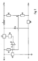
- the choke converter according to the invention shown in FIG. 1 contains a controllable one Switch LS and a choke L, which in a manner known per se between an input terminal Ue and a first output terminal Ua + are connected in series.
- the Connection point between the controllable switch LS and the choke L is with the Cathode of a freewheeling diode D connected.
- the anode of the freewheeling diode D is grounded and connected to one end of a current measuring resistor RM.
- the other end of the Current measuring resistor RM is connected to a second output terminal Ua.
- first resistor R1 is connected between the input terminal Ue and a point B, the via a second resistor R2 with the first output terminal Ua + and a third resistor R3 is connected to the second output terminal Ua.
- the Point B is also connected to the inverting input of a first comparator K1, its output via a driver TR with a control input of the controllable Switch LS is connected.
- the non-inverting input of the first comparator K1 is connected to a first reference voltage source U1, which is between the input terminal Ue and ground is switched.
- the first comparator K1 and the first reference voltage source U1 are connected together in such a way that that the reference voltage supplied by the first reference voltage source U1 Uref1 (point A) takes two different values, depending on whether the The output of the first comparator K1 is "low” or "high", i.e. the first comparator K1 exhibits hysteresis because its breakover voltage (point A) has a value other than its reverse tipping voltage (point A).
- point B there is a potential that is created by the Voltage drops across the resistors R1, R2, R3 and RM is determined and thus by the input voltage, the output voltage and the output current.
- the Input voltage is namely through the first, third and the current measuring resistor divided the output voltage by the second and third resistor.
- the first comparator K1 compares the voltage at point B with the voltage at point A. As long as the voltage at point B is less than the voltage at point A, the is Output of the first comparator K1 to "high” and vice versa: the output of the first Comparator K1 is "low” as long as the voltage at point B is greater than that Voltage at point A.
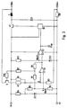
- FIG. 2 A preferred embodiment of the choke converter according to the invention is shown in FIG. 2 shown. This embodiment differs from the choke converter according to the invention 1 by an arrangement for switching off the choke converter low input voltage and an arrangement for preventing the discharge of a accumulator connected to the choke converter via the choke converter low input voltage.
- the arrangement for switching off the choke converter at low input voltage has a second reference voltage source U2, which is between the input terminal Ue and ground is connected, and a second comparator K2, the non-inverting Input with the output of the first comparator K1, its inverting Input with the second reference voltage source U2 and its output with the Driver TR is connected.
- the second comparator K2 compares the output voltage of the first comparator K1 with one of the second reference voltage source U2 supplied second reference voltage Uref2. At low input voltage, i.e. as long as the input voltage is below the second reference voltage Uref2, the output of the second comparator K2 remains at "low", so that the driver TR the controllable switch LS is kept open and the throttle converter does not oscillate can.
- the input voltage is above the second reference voltage URef2
- the output voltage of the second comparator K2 follows the output voltage of the first comparator K1, i.e. the controllable switch LS is from the first Comparator K1 controlled via the second comparator K2 and the driver TR.
- the arrangement for preventing the discharge of a connected to the choke converter Accumulator points over the choke converter at low input voltage a second controllable switch S between the second resistor R2 and the first output terminal Ua + is arranged, and its control input via a tenth resistor R10 is connected to the input terminal Ue.
- the second Controllable switch S preferably consists of an electronic switch, for example a transistor whose base is connected to the tenth resistor R10 is. When the input voltage is low, the second controllable switch S is open, so that the output resistance of the choke converter is practically infinite, and the Accumulator cannot discharge through the second and third resistor R2, R3.
- the first reference voltage source U1 consists of a fourth, fifth and sixth resistor R4, R5, R6 connected in series between the input terminal Ue and ground are connected, and a first Zener diode ZD1, the anode of which Ground and one end of the sixth resistor R6 is connected and the Cathode is connected to the fourth and fifth resistor R4, R5.
- the other The end of the sixth resistor R6 is connected to the non-inverting input of the first Comparator K1 (point A) and one end of an eighth resistor R8 connected.
- the other end of the eighth resistor R8 is through a seventh resistor R7 with the input terminal Ue and via a ninth resistor R9 with the output of the first comparator K1.
- the second reference voltage source U2 consists of a second Zener diode ZD2, its anode with ground and its cathode with the inverting input of the second comparator K2 and an eleventh Resistor R11 is connected to the input terminal Ue.
- the reference voltage Uref1 (point A) is the Zener voltage divided across the fifth and sixth resistors R5, R6, that from the input voltage through the fourth resistor R4 and the first Zener diode ZD1 is generated. As mentioned above, it has two different types Values depending on whether the output of the first comparator is "low” or “high”. Lies namely the output of the first comparator K1 to "high”, the voltage is on Point A (breakdown voltage) by the divided Zener voltage and the over sixth, seventh and eighth resistor R6, R7, R8 divided input voltage certainly. If, on the other hand, the output of the first comparator K1 is at "low”, So is the ninth resistor R9 of the series circuit from the sixth and eighth Resistor R6, R8 connected in parallel.
- the voltage at point A due to the divided Zener tension and the one above the sixth, seventh and eighth resistor R6, R7, R8 and on the other hand the seventh and ninth resistor R7, R9 divided input voltage determined.
- the difference the hysteresis voltage is between the breakover voltage and the breakdown voltage.
- the seventh R7 and ninth resistor R9 also serve as pull-up resistors for the output of the first comparator K1.
- the output of the first comparator K1 is "low", i.e. the output voltage of the first comparator K1 the reference voltage Uref2 of the second reference voltage source Does not exceed U2, the output of the second comparator K2 remains also on “low”.
- the driver TR is not activated and the controllable one Switch LS remains open.
- the output of the first comparator K1 is present "high”, i.e. the output voltage of the first comparator K1 is greater than that Reference voltage Uref2 of the second reference voltage source U2, is also the Output of the second comparator K2 to "high”. This controls the driver TR, if not the output of the second comparator K2 via the control input Stop a shutdown signal is supplied.
Landscapes
- Engineering & Computer Science (AREA)
- Power Engineering (AREA)
- Dc-Dc Converters (AREA)
Applications Claiming Priority (2)
| Application Number | Priority Date | Filing Date | Title |
|---|---|---|---|
| DE19932379 | 1999-07-13 | ||
| DE19932379A DE19932379A1 (de) | 1999-07-13 | 1999-07-13 | Drosselwandler |
Publications (2)
| Publication Number | Publication Date |
|---|---|
| EP1069672A2 true EP1069672A2 (fr) | 2001-01-17 |
| EP1069672A3 EP1069672A3 (fr) | 2002-02-20 |
Family
ID=7914400
Family Applications (1)
| Application Number | Title | Priority Date | Filing Date |
|---|---|---|---|
| EP00113753A Withdrawn EP1069672A3 (fr) | 1999-07-13 | 2000-06-29 | Alimentation à découpage avec bobine de transformateur |
Country Status (7)
| Country | Link |
|---|---|
| US (1) | US6452369B1 (fr) |
| EP (1) | EP1069672A3 (fr) |
| JP (1) | JP2001069751A (fr) |
| KR (1) | KR20010049751A (fr) |
| CN (1) | CN100392966C (fr) |
| DE (1) | DE19932379A1 (fr) |
| TW (1) | TW591861B (fr) |
Cited By (1)
| Publication number | Priority date | Publication date | Assignee | Title |
|---|---|---|---|---|
| US9124118B2 (en) | 2011-09-16 | 2015-09-01 | Braun Gmbh | Circuit for a small electric appliance with an accumulator and method for measuring a charging current |
Families Citing this family (13)
| Publication number | Priority date | Publication date | Assignee | Title |
|---|---|---|---|---|
| ITTO20020545A1 (it) * | 2002-06-21 | 2003-12-22 | St Microelectronics Srl | Circuito di controllo in modalita' pwm per la post-regolazione di alimentatori a commutazione a molte uscite |
| EP1639684A2 (fr) * | 2003-06-27 | 2006-03-29 | Maxwell Technologies, Inc. | Systeme de stockage d'energie |
| DK1544703T3 (da) | 2003-12-15 | 2008-09-08 | Dialog Semiconductor Gmbh | Strömdetekteringskreds til DC/DC downkonvertere |
| JP2005287274A (ja) * | 2004-03-31 | 2005-10-13 | Honda Motor Co Ltd | 降圧型dc−dcコンバータ |
| US7592793B2 (en) * | 2006-06-30 | 2009-09-22 | System General Corp. | Voltage regulator providing power from AC power source |
| JP2008129693A (ja) * | 2006-11-17 | 2008-06-05 | Sanken Electric Co Ltd | ドロッパ型レギュレータ |
| CN102063143B (zh) * | 2010-11-10 | 2012-10-31 | 中国兵器工业集团第二一四研究所苏州研发中心 | 一种缓变电源管理电路 |
| US9444331B2 (en) * | 2013-07-29 | 2016-09-13 | Infineon Technologies Ag | System and method for a converter circuit |
| KR101634273B1 (ko) | 2014-12-11 | 2016-06-29 | 동국대학교 산학협력단 | 벅 컨버터 |
| JP5990352B1 (ja) * | 2016-01-26 | 2016-09-14 | 株式会社アウルソリューション | 電源回路およびその電源回路を備えた電子機器 |
| JP6606038B2 (ja) * | 2016-09-06 | 2019-11-13 | 株式会社東芝 | 出力電圧制御回路 |
| US10566971B2 (en) * | 2017-08-23 | 2020-02-18 | Honeywell International Inc. | Adaptive proximity sensor |
| CN110445395A (zh) * | 2019-08-13 | 2019-11-12 | 苏州格远电气有限公司 | 宽电压范围直流输入开关电源 |
Family Cites Families (27)
| Publication number | Priority date | Publication date | Assignee | Title |
|---|---|---|---|---|
| US4428015A (en) * | 1981-12-22 | 1984-01-24 | Hughes Aircraft Company | Overcurrent limiter circuit for switching regulator power supplies |
| IT1151378B (it) * | 1982-03-30 | 1986-12-17 | Fiar Spa | Dispositivo elettronico di controllo della tensione |
| JPS5925533A (ja) * | 1982-07-31 | 1984-02-09 | 松下電工株式会社 | 急速充電回路 |
| JPH0655030B2 (ja) * | 1982-12-08 | 1994-07-20 | 富士電機株式会社 | 負荷電流の瞬時値制御方法 |
| DE3310678C2 (de) | 1983-03-24 | 1986-09-25 | Braun Ag, 6000 Frankfurt | Schaltung zur Regelung der Ausgangsspannung eines elektronischen Schaltnetzteiles |
| JPS6032565A (ja) | 1983-07-30 | 1985-02-19 | Matsushita Electric Works Ltd | 電源回路 |
| US4630187A (en) * | 1985-09-09 | 1986-12-16 | Sperry Corporation | Power converter with duty ratio quantization |
| FR2610149B1 (fr) * | 1987-01-22 | 1989-04-07 | Telecommunications Sa | Convertisseur continu-continu a rendement eleve a faible charge |
| US4929882A (en) * | 1987-06-23 | 1990-05-29 | National Semiconductor Corporation | Apparatus for converting DC to DC having non-feed back variable hysteretic current-mode control for maintaining approximately constant frequency |
| JPH02168864A (ja) * | 1988-12-19 | 1990-06-28 | Origin Electric Co Ltd | 直流電源装置 |
| DE3921955C2 (de) * | 1989-07-04 | 2000-02-03 | Bosch Gmbh Robert | Verfahren zur Erzeugung eines Stellsignals für einen Schaltregler |
| US5359281A (en) * | 1992-06-08 | 1994-10-25 | Motorola, Inc. | Quick-start and overvoltage protection for a switching regulator circuit |
| EP0689731A1 (fr) * | 1993-03-17 | 1996-01-03 | National Semiconductor Corporation | Circuit de glissemant de fréquence pour régulateur à découpage |
| US5481178A (en) * | 1993-03-23 | 1996-01-02 | Linear Technology Corporation | Control circuit and method for maintaining high efficiency over broad current ranges in a switching regulator circuit |
| JPH0715952A (ja) | 1993-06-29 | 1995-01-17 | Toshiba Lighting & Technol Corp | 電源装置,ランプ点灯装置及び照明装置 |
| JP3427436B2 (ja) * | 1993-09-16 | 2003-07-14 | 株式会社デンソー | 駆動回路 |
| US5563781A (en) * | 1993-11-24 | 1996-10-08 | Integrated Technology Corporation | Dual-mode power converter |
| JPH07182052A (ja) * | 1993-12-21 | 1995-07-21 | Zexel Corp | 過電圧保護装置 |
| US5552695A (en) * | 1994-03-22 | 1996-09-03 | Linear Technology Corporation | Synchronously rectified buck-flyback DC to DC power converter |
| EP0752748B1 (fr) | 1995-06-07 | 1999-03-31 | STMicroelectronics S.r.l. | Chargeur de batterie à fonction multiple qui est autoconfiguerable comme régulateur de tension pour des appareils alimentés par batteries |
| US5734259A (en) * | 1995-09-29 | 1998-03-31 | Cherry Semiconductor Corporation | Balanced delta current method for current control in a hysteretic power supply |
| DE19612365A1 (de) | 1996-03-28 | 1997-10-02 | Telefunken Microelectron | Gleichspannungs-Abwärtswandler für hohe Eingangsspannungen |
| WO1998024170A1 (fr) | 1996-11-22 | 1998-06-04 | Siemens Aktiengesellschaft | Regulateur a deux points paliers, a assise profonde et a oscillation libre |
| IES80825B2 (en) | 1997-09-09 | 1999-03-10 | James Christopher Lacey | Improved dc/dc converter |
| WO1999017434A1 (fr) * | 1997-09-30 | 1999-04-08 | Mitsubishi Denki Kabushiki Kaisha | Systeme de filtre actif de suralimentation et unite de commande de ce filtre actif de suralimentation |
| US5926383A (en) * | 1998-03-20 | 1999-07-20 | Lucent Technologies Inc. | Integrated protection circuit for a power converter and method of operation thereof |
| US6111391A (en) * | 1998-09-11 | 2000-08-29 | Cullen; Richard A. | Controller for solar electric generator for recreational vehicles |
-
1999
- 1999-07-13 DE DE19932379A patent/DE19932379A1/de not_active Withdrawn
-
2000
- 2000-06-29 EP EP00113753A patent/EP1069672A3/fr not_active Withdrawn
- 2000-07-03 TW TW089113129A patent/TW591861B/zh not_active IP Right Cessation
- 2000-07-07 US US09/611,786 patent/US6452369B1/en not_active Expired - Fee Related
- 2000-07-10 KR KR1020000039207A patent/KR20010049751A/ko not_active Withdrawn
- 2000-07-10 CN CNB001098381A patent/CN100392966C/zh not_active Expired - Fee Related
- 2000-07-13 JP JP2000213249A patent/JP2001069751A/ja active Pending
Cited By (1)
| Publication number | Priority date | Publication date | Assignee | Title |
|---|---|---|---|---|
| US9124118B2 (en) | 2011-09-16 | 2015-09-01 | Braun Gmbh | Circuit for a small electric appliance with an accumulator and method for measuring a charging current |
Also Published As
| Publication number | Publication date |
|---|---|
| HK1033391A1 (zh) | 2001-08-24 |
| JP2001069751A (ja) | 2001-03-16 |
| TW591861B (en) | 2004-06-11 |
| CN100392966C (zh) | 2008-06-04 |
| KR20010049751A (ko) | 2001-06-15 |
| CN1280414A (zh) | 2001-01-17 |
| DE19932379A1 (de) | 2001-01-18 |
| EP1069672A3 (fr) | 2002-02-20 |
| US6452369B1 (en) | 2002-09-17 |
Similar Documents
| Publication | Publication Date | Title |
|---|---|---|
| DE69406407T2 (de) | Schaltungskreis zum Laden von wiederaufladbaren Batterien | |
| DE102008033466B4 (de) | Integrierender Stromregler und Verfahren zur Stromreglung | |
| EP0162341B1 (fr) | Dispositif d'alimentation à commutation électronique | |
| DE102005055160B4 (de) | Regelschaltung zur Strom- und Spannungregelung in einem Schaltnetzteil | |
| DE10355670B4 (de) | Verfahren zur Ansteuerung eines Schalters in einer Leistungsfaktorkorrekturschaltung und Ansteuerschaltung | |
| DE69508746T2 (de) | Selbstkonfigurierendes Batterieladegerät mit Mehrfachfunktionen als Versorgungsspannungsregler für batteriebetriebene Geräte | |
| EP1069672A2 (fr) | Alimentation à découpage avec bobine de transformateur | |
| EP1149455B1 (fr) | Procede et dispositif pour charger des accumulateurs | |
| EP0170932A1 (fr) | Circuit pour alimenter des charges électriques à travers un hacheur de régulation | |
| DE69512254T2 (de) | Ladungsvorrichtung zum laden von wiederaufladbaren batterien mit einer temperaturabhängigen beendigung des ladevorganges und wiederaufladbare batterie mit einem temperatur anzeigenden dehnstreifen | |
| WO2009059657A2 (fr) | Circuit électrique avec une cascade d'accumulateurs | |
| EP2128969A2 (fr) | Régulateur de commutation doté d'un régulateur PWM | |
| DE60026342T2 (de) | Schalter mit elektromagnetischer rückstosskraft. | |
| EP0727062A1 (fr) | Alimentation a decoupage | |
| EP0635171B1 (fr) | Bloc electronique d'alimentation a decoupage | |
| DE3300285C2 (de) | Elektronisches Schaltnetzteil | |
| EP1206830A1 (fr) | Alimentation a decoupage pourvue d'un dispositif limitant la tension de sortie | |
| WO1994014221A1 (fr) | Partie electronique de reseau combinatoire pour charger un accumulateur | |
| DE102024114945B3 (de) | Schaltvorrichtung für die überwachte Bereitstellung einer Gleichspannung an einem aktiven elektrischen Verbraucher | |
| DE19633664A1 (de) | Elektrisches Gerät mit Energiespeicher | |
| DE3311737C2 (de) | Elektronisches Schaltnetzteil | |
| DE10205706B4 (de) | Ansteuerschaltung für einen Schalter in einem Schaltnetzteil | |
| DE10255357B4 (de) | Gleichspanungswandlerschaltung und Verfahren zur Gleichspannungswandlung | |
| DE3837561A1 (de) | Gleichspannungswandler nach dem prinzip des eintaktdurchflusswandlers | |
| DE69903124T2 (de) | Betriebsschaltung für eine schwingende Last |
Legal Events
| Date | Code | Title | Description |
|---|---|---|---|
| PUAI | Public reference made under article 153(3) epc to a published international application that has entered the european phase |
Free format text: ORIGINAL CODE: 0009012 |
|
| AK | Designated contracting states |
Kind code of ref document: A2 Designated state(s): AT BE CH CY DE DK ES FI FR GB GR IE IT LI LU MC NL PT SE |
|
| AX | Request for extension of the european patent |
Free format text: AL;LT;LV;MK;RO;SI |
|
| PUAL | Search report despatched |
Free format text: ORIGINAL CODE: 0009013 |
|
| RIC1 | Information provided on ipc code assigned before grant |
Free format text: 7H 02M 1/00 A, 7H 02J 7/00 B, 7H 02M 3/156 B |
|
| AK | Designated contracting states |
Kind code of ref document: A3 Designated state(s): AT BE CH CY DE DK ES FI FR GB GR IE IT LI LU MC NL PT SE |
|
| AX | Request for extension of the european patent |
Free format text: AL;LT;LV;MK;RO;SI |
|
| 17P | Request for examination filed |
Effective date: 20020717 |
|
| AKX | Designation fees paid |
Free format text: AT BE CH CY DE DK ES FI FR GB GR IE IT LI LU MC NL PT SE |
|
| 17Q | First examination report despatched |
Effective date: 20090507 |
|
| STAA | Information on the status of an ep patent application or granted ep patent |
Free format text: STATUS: THE APPLICATION IS DEEMED TO BE WITHDRAWN |
|
| 18D | Application deemed to be withdrawn |
Effective date: 20120103 |