EP1069449B1 - Beleuchtungseinrichtung für ein DUV-Mikroskop - Google Patents
Beleuchtungseinrichtung für ein DUV-Mikroskop Download PDFInfo
- Publication number
- EP1069449B1 EP1069449B1 EP00111442A EP00111442A EP1069449B1 EP 1069449 B1 EP1069449 B1 EP 1069449B1 EP 00111442 A EP00111442 A EP 00111442A EP 00111442 A EP00111442 A EP 00111442A EP 1069449 B1 EP1069449 B1 EP 1069449B1
- Authority
- EP
- European Patent Office
- Prior art keywords
- duv
- illumination
- reflection
- beam path
- reflection filter
- Prior art date
- Legal status (The legal status is an assumption and is not a legal conclusion. Google has not performed a legal analysis and makes no representation as to the accuracy of the status listed.)
- Expired - Lifetime
Links
- 238000005286 illumination Methods 0.000 title claims description 73
- 230000003595 spectral effect Effects 0.000 claims description 12
- 230000003287 optical effect Effects 0.000 claims description 6
- VYPSYNLAJGMNEJ-UHFFFAOYSA-N Silicium dioxide Chemical compound O=[Si]=O VYPSYNLAJGMNEJ-UHFFFAOYSA-N 0.000 claims description 3
- PNEYBMLMFCGWSK-UHFFFAOYSA-N aluminium oxide Inorganic materials [O-2].[O-2].[O-2].[Al+3].[Al+3] PNEYBMLMFCGWSK-UHFFFAOYSA-N 0.000 claims 1
- 229910052681 coesite Inorganic materials 0.000 claims 1
- 229910052593 corundum Inorganic materials 0.000 claims 1
- 229910052906 cristobalite Inorganic materials 0.000 claims 1
- 239000000377 silicon dioxide Substances 0.000 claims 1
- 229910052682 stishovite Inorganic materials 0.000 claims 1
- 239000000758 substrate Substances 0.000 claims 1
- 239000012780 transparent material Substances 0.000 claims 1
- 229910052905 tridymite Inorganic materials 0.000 claims 1
- 229910001845 yogo sapphire Inorganic materials 0.000 claims 1
- 230000010287 polarization Effects 0.000 description 8
- 230000001419 dependent effect Effects 0.000 description 7
- 230000005540 biological transmission Effects 0.000 description 5
- 238000010276 construction Methods 0.000 description 3
- 230000000694 effects Effects 0.000 description 3
- 239000011521 glass Substances 0.000 description 3
- 239000000463 material Substances 0.000 description 3
- 229910004298 SiO 2 Inorganic materials 0.000 description 2
- 238000001228 spectrum Methods 0.000 description 2
- 229910018072 Al 2 O 3 Inorganic materials 0.000 description 1
- 239000012876 carrier material Substances 0.000 description 1
- 238000006073 displacement reaction Methods 0.000 description 1
- 230000008020 evaporation Effects 0.000 description 1
- 238000001704 evaporation Methods 0.000 description 1
- 230000003760 hair shine Effects 0.000 description 1
- 229910052736 halogen Inorganic materials 0.000 description 1
- 150000002367 halogens Chemical class 0.000 description 1
- 238000003384 imaging method Methods 0.000 description 1
- 229910052753 mercury Inorganic materials 0.000 description 1
- 150000002730 mercury Chemical class 0.000 description 1
- 229910052751 metal Inorganic materials 0.000 description 1
- 239000002184 metal Substances 0.000 description 1
- 238000000034 method Methods 0.000 description 1
- 238000001000 micrograph Methods 0.000 description 1
- 210000001747 pupil Anatomy 0.000 description 1
- 230000000284 resting effect Effects 0.000 description 1
- 230000002441 reversible effect Effects 0.000 description 1
- 230000007704 transition Effects 0.000 description 1
- 238000007740 vapor deposition Methods 0.000 description 1
Images


Classifications
-
- G—PHYSICS
- G02—OPTICS
- G02B—OPTICAL ELEMENTS, SYSTEMS OR APPARATUS
- G02B21/00—Microscopes
- G02B21/16—Microscopes adapted for ultraviolet illumination ; Fluorescence microscopes
Definitions
- the invention relates to a lighting device for a DUV microscope with the features of the preamble of independent claim 1, as known from DE-A-2 010 540.
- the DUV wavelength band is characterized by the peak spectral position and the half width of its peak.
- narrow band transmission filter systems and reflection filter systems are known. These filter systems are inserted into the illumination beam path and filter out of the light spectrum of a light source a desired DUV wavelength band as useful light.
- the microscope image is visualized with a DUV-sensitive TV camera.
- Transmission narrow band filter systems in the DUV provide very narrow peaks, this is due to the maximum transmission and thus the peak value of the peak only about 20 percent of the light intensity in front of the transmission narrow band filter system.
- weak intensities require particularly sensitive ones and thus technologically complex and very expensive cameras.
- these cameras for example in so-called "frame transfer CCD imagers"
- they have very long exposure and image readout times have, so that a "life" observation of the object is impossible. This is especially disturbing when the object table move with the resting object must become.
- ⁇ 45 ° and reflected.
- the peak of the peak well over 90 percent.
- Their disadvantage, however, is in that its half width is about 30 to 50 nm.
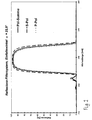
- the invention is based on the consideration that the large half-widths essentially by polarization effects on the reflection filter systems caused. These are much smaller for smaller angles of reflection. Therefore, in a DUV lighting device according to the invention, a reflection filter system with small reflection angles and spectrally adapted Reflection filters used.
- An illumination device for a DUV microscope has a light source emanating from an illumination beam path.
- Illumination beam path are a collector and a reflection filter system arranged to produce a desired DUV wavelength band.
- the Reflection filter system consists of four reflection filters, to which the illumination beam path each reflected at the same angle of reflection a.
- the illumination beam path runs in front of and behind the reflection filter system coaxial.
- the reflection angle a at the individual reflection filters between ⁇ ⁇ 30 °.
- the reflection filter system delivers a very narrow DUV wavelength band ⁇ DUV + ⁇ with a half width of max. 20 nm. It has a peak with a peak value S of more than 90% of the incident light intensity. Depending on the reflection filters used, a peak peak value S of more than 98% of the irradiated light intensity can be achieved by means of a reflection filter system with small angles of incidence.
- reflection filters tuned to the desired DUV wavelength band ⁇ DUV + ⁇ are used in the reflection filter system of the illumination device according to the invention.
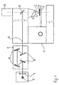
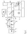
- FIG. 1 shows a microscope 1 with objectives 2 and an object 4 lying on a stage 3.
- an illumination beam path 6 goes out, passes through a collector 7 and constructed of four reflection filters 8 reflection filter system 9.
- From there the illumination beam path 6 passes through an illumination optical system, not shown, is deflected at a beam splitter 10 and through the lens 2 on the Object 4 focused.
- the imaging beam path emanating from the object 4 passes through the objective 2 and the beam splitter 10 to the TV camera 11.
- the reflection filters 8 in the reflection filter system 9 are so arranged that the illumination beam path 6 at all reflection filters. 8 impinges with the same small angle of incidence ⁇ .
- ⁇ is an angle of 30 °. Smaller angles are possible according to the invention.
- reflection filter systems can with angles of incidence ⁇ ⁇ 15 ° because of the narrow geometry only be realized with difficulty.
- the desired DUV wavelength range matched reflection filter 8 of vapor deposition layers are applied to black glass.
- the desired DUV portion of the lamp light is reflected.
- the passing through the evaporation layers shares the lamp light, so the remaining DUV share and the UV and VIS components are absorbed in the black glass. This way arises a lighting with only the desired DUV wavelength range ,
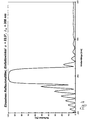
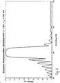
- FIGS. 3-5 show the wavelength-dependent reflection at different individual reflection filters, which are designed for different angles of incidence ⁇ .
- the reflection filters have a layer structure as indicated in Table 1. Only the thicknesses of the layers are corrected according to the desired angle of incidence ⁇ by a reference wavelength ⁇ 0 , which is included in the calculation of the layer thicknesses. The associated reference wavelengths ⁇ 0 are given in the figures. By adapting the layer thicknesses, the reflection filters also have qualitatively the same reflection behavior for different angles of incidence.
- FIG. 6 shows the reference wavelength ⁇ 0 as a function of the angle of incidence ⁇ . It can be seen that for changes to larger angles of incidence the reference wavelength ⁇ 0 must be corrected much more strongly.
- the layer system from Table 1 is suitable again.
- a reflection filter system suitable in each case for a narrow DUV wavelength band can be specified for at least one DUV wavelength between 180 and 300 nm.
- Fig. 8 shows a switchable illumination device for either VIS or DUV illumination, which is equipped with two separate light sources for two wavelength ranges.
- the structure corresponds in principle to FIG. 1.
- the same components have the same reference numerals.
- the already described illumination device from FIG. 1 with the DUV light source 5 is supplemented by an additional VIS light source 12 for the visible spectral range.
- This VIS light source 12 is, for example, a Hg incandescent lamp which emits only spectral components in the VIS wavelength range, but none in the UV and DUV wavelength ranges.
- this VIS light source 12 passes through a collector 13 and is only vertically coupled into the illumination beam path 6 when an additionally installed, pivotable mirror 14 in the illumination beam path 6 is in the position "b". Then, the VIS light arrives on the following part of the illumination beam path 6 to the object 4. To adjust a DUV illumination, the pivoting mirror 14 is brought into the position "a”. Then the light of the DUV light source 5, as in FIG. 1 , arrives at the object 4.
- the structure described requires a second light source, but is through easy to realize the pivoting mirror 14.
- the structure expands the possibilities of using the microscope considerably. This is how the DUV light source shines 5, e.g. a Hg arc lamp, although also in the UV and VIS wavelengths from. However, it has only a small arc, the with weaker VIS lenses the pupil can not fill and thus no lighting for these lenses allows.
- the DUV light source is 5 not dimmable.
- the VIS light source e.g. a halogen bulb, a sufficiently large filament for sufficient illumination with weaker VIS lenses and is dimmable.
- UV or DUV shares show her Spectrum not on. Therefore, with the described construction, a DUV microscope be equipped with all possibilities of VIS viewing.
- FIG. 9 shows the different position of the images of a universal light source for the VIS and UV and DUV wavelength ranges in a DUV illumination device.
- the light of the light source 15 passes through a collector 16 and a reflection filter system 9, which is composed of four reflection filters 8.
- the reflection filters 8 are vapor-deposited on black glass.
- the different layers of the image 17 of the light source 15 for the DUV wavelength 248 nm, the so-called "i-line” 365 nm and the visible VIS wavelength range are shown schematically.
- the light source 15 would have for different spectral illumination method in the direction of the illumination beam path 6 are moved.
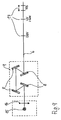
- FIGS. 10-11 Shown is a reversible illumination device for either VIS or DUV lighting, which works with only one universal DUV-VIS light source.
- the DUV light source 5 is taken, which is for example a Hg arc lamp.
- From the DUV light source 5 emits an illumination beam path 6, in which a collector 7 and a reflection filter system 9 with four reflection filters 8 are arranged.
- the four reflection filters 8 are designated here individually for distinguishing their spatial position with 8a, 8b, 8c and 8d.
- the reflection filters 8a, 8b, 8c and 8d are vapor-deposited in this example on a carrier material which is transparent to all wavelength ranges, ie quartz glass.
- Fig.10 shows the lighting device described in the switching stage "DUV lighting".
- a light stopper 18 is inserted between the reflection filter 8a and the reflection filter 8d.
- This can be any opaque plate, eg made of metal. Thereby, the passing through the reflection filter 8a portion of the lamp light is stopped, so that only the reflected DUV wavelength band is used for illumination.
- the position 17 of the image of the light source 5 is indicated.
- FIG. 11 shows the illumination device described in the switching stage "VIS illumination".
- a combination of lenses 19 and at least one filter 20 is inserted between the reflection filter 8a and the reflection filter 8d, which are selected for the VIS range.
- the lenses 19 shift the position 17 of the VIS image of the light source to the position of the DUV image of the light source.
- the filter 20 may be a color filter or gray filter, etc.
- a light stopper 18 is inserted between the reflection filter 8b and the reflection filter 8d to exclude any DUV component from the illumination during the VIS illumination.
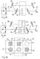
- Fig. 12 shows a linear slide 21, with which the two switching stages of Fig. 10 and Fig. 11 and another switching stages can be further realized.
- the linear slider 21 has three buttons 22, 23, 24 for different spectral illumination variants.
- the linear slider 21 is inserted vertically into the illumination beam path 6 in the reflection filter system 9, so that its upper half is always between the reflection filter 8b and the reflection filter 8c and its lower half is always between the reflection filter 8a and the reflection filter 8d.
- optionally only one of the buttons 22, 23, 24 is inserted into the illumination beam path 6.
- the position 28 of the reflection filter system is represented by a dashed frame. In FIG. 12 , therefore, the button 23 is currently inserted in the reflection filter system.
- the button 22 generates a DUV illumination, thus corresponds to FIG. 10 .
- a free opening 25 is arranged to pass the DUV light.
- a light stopper 18 is arranged in its lower half.
- the button 23 generates a VIS illumination, thus corresponds to FIG. 11 .
- a light stopper 18 is arranged to stop the DUV light.
- a lens-filter combination 26 of lenses and at least one filter is inserted, which are selected for the VIS range.
- the lenses correct the position of the image of the light source.
- the filters are freely selectable, eg color filters, gray filters, fluorescence filters etc.
- buttons 24 With the button 24, another illumination with wavelengths au-ßer distress of the DUV wavelength band.
- a light stopper 18 is arranged to stop the DUV light.
- any lens-filter combination 27 is inserted, which is selected for example for the so-called "i-line" at 365 nm.
Landscapes
- Physics & Mathematics (AREA)
- Chemical & Material Sciences (AREA)
- Analytical Chemistry (AREA)
- General Physics & Mathematics (AREA)
- Optics & Photonics (AREA)
- Microscoopes, Condenser (AREA)
- Optical Filters (AREA)
Description
- Fig. 1:
- eine erfindungsgemäße DUV-Beleuchtungseinrichtung für ein Mikroskop;
- Fig. 2:
- wellenlängenabhängige Reflexion an einem Reflexionsfilter-System mit einem kleinen Einfallswinkel α = 22,5, aufgeteilt in Polarisationsanteile;
- Fig. 3:
- wellenlängenabhängige Reflexion an einem einzelnen Reflexionsfilter für einen Einfallswinkel α = 15° und eine Bezugswellenlänge λ0 = 303,5 nm;
- Fig. 4:
- wellenlängenabhängige Reflexion an einem einzelnen Reflexionsfilter für einen Einfallswinkel α = 22,5° und eine Bezugswellenlänge λ0= 308 nm;
- Fig. 5:
- wellenlängenabhängige Reflexion an einem einzelnen Reflexionsfilter für einen Einfallswinkel α = 30° und eine Bezugswellenlänge λ0= 314 nm;
- Fig. 6:
- Bezugswellenlänge λ0 in Abhängigkeit von dem Einfallswinkel α;
- Fig. 7:
- wellenlängenabhängige Reflexion für drei auf verschiedene DUV-Wellenlängen angepaßte Reflexionsfilter-Systeme, jeweils mit einem Einfallswinkel α = 22,5 ,
- Fig. 8:
- umschaltbare Beleuchtungseinrichtung für wahlweise VIS- oder DUV-Beleuchtung mit zwei separaten DUV- und VIS-Lichtquellen;
- Fig. 9:
- Lage der Lampenbilder für VIS, UV, DUV in einer DUV- Beleuchtungseinrichtung mit einer universellen DUV-VIS-Lichtquelle;
- Fig.10:
- umschaltbare Beleuchtungseinrichtung für wahlweise VIS- oder DUV-Beleuchtung mit einer universellen DUV-VIS-Lichtquelle in der Schaltstufe "DUV-Beleuchtung";
- Fig.11:
- umschaltbare Beleuchtungseinrichtung aus Fig.10 für wahlweise VIS-oder DUV-Beleuchtung mit einer universellen DUV-VIS-Lichtquelle in des Schaltstufe "VIS-Beleuchtung";
- Fig. 12:
- Linearschieber für die umschaltbare Beleuchtungseinrichtung aus Fig. 10 und Fig. 11 mit drei Schaltflächen;
| Schichtaufbau eines Reflexionsfilters | |||||
| es sind: L = Al2O3 ; S = SiO2 ; λ0 = 308 nm ; α = 22.5° | |||||
| Nr. | Dicke [λ 0 /4] | Material | Nr. | Dicke [λ 0 /4] | Material |
| 1 | 0,25 | L | 29 | 0,92 | L |
| 2 | 0,94 | S | 30 | 0,72 | S |
| 3 | 0,66 | L | 31 | 0,92 | L |
| 4 | 0,72 | S | 32 | 0,72 | S |
| 5 | 0,92 | L | 33 | 0,92 | L |
| 6 | 0,72 | S | 34 | 0,72 | S |
| 7 | 0,92 | L | 35 | 0,92 | L |
| 8 | 0,72 | S | 36 | 0,72 | S |
| 9 | 0,92 | L | 37 | 0,92 | L |
| 10 | 0,72 | S | 38 | 0,72 | S |
| 11 | 0,92 | L | 39 | 0,92 | L |
| 12 | 0,72 | S | 40 | 0,72 | S |
| 13 | 0,92 | L | 41 | 0,92 | L |
| 14 | 0,72 | S | 42 | 0,72 | S |
| 15 | 0,92 | L | 43 | 0,92 | L |
| 16 | 0,72 | S | 44 | 0,72 | S |
| 17 | 0,92 | L | 45 | 0,92 | L |
| 18 | 0,72 | S | 46 | 0,72 | S |
| 19 | 0,92 | L | 47 | 0,92 | L |
| 20 | 0,72 | S | 48 | 0,72 | S |
| 21 | 0,92 | L | 49 | 0,92 | L |
| 22 | 0,72 | S | 50 | 0,72 | S |
| 23 | 0,92 | L | 51 | 0,92 | L |
| 24 | 0,72 | S | 52 | 0,72 | S |
| 25 | 0,92 | L | 53 | 0,92 | L |
| 26 | 0,72 | S | 54 | 0,67 | S |
| 27 | 0,92 | L | 55 | 0,68 | L |
| 28 | 0,72 | S | 56 | 1,75 | S |
- 1:
- Mikroskop
- 2:
- Objektiv
- 3:
- Objekttisch
- 4:
- Objekt
- 5:
- DUV-Lichtquelle
- 6:
- Beleuchtungsstrahlengang
- 7:
- Kollektor
- 8:
- Reflexionsfilter, auch 8a, 8b, 8c, 8d
- 9:
- Reflexionsfilter-System
- 10:
- Strahlteiler
- 11:
- TV-Kamera
- 12:
- VIS-Lichtquelle
- 13:
- Kollektor
- 14:
- schwenkbarer Spiegel
- 15:
- universelle DUV-VIS-Lichtquelle
- 16:
- Kollektor
- 17:
- Bild der Lichtquelle
- 18:
- Licht-Stopper
- 19:
- Linsen
- 20:
- Filter
- 21:
- Linearschieber
- 22:
- Schaltfläche für DUV-Beleuchtung
- 23:
- Schaltfläche für VIS-Beleuchtung
- 24:
- Schaltfläche für eine weitere Beleuchtung
- 25:
- freie Öffnung
- 26:
- Linsen-Filter-Kombination für VIS-Beleuchtung
- 27:
- Linsen-Filter-Kombination für eine weitere Beleuchtung
- 28:
- Position des Reflexionsfilter-Systems
Claims (8)
- Beleuchtungseinrichtung für ein DUV-Mikroskop (1) mit einem von einer DUV-Lichtquelle (5) ausgehenden Beleuchtungsstrahlengang (6), in dem ein Kollektor (7) und ein Reflexionsfilter-System (9) angeordnet sind, welches ein DUV-Wellenlängenband erzeugt und dadurch gekennzeichnet, daß das Reflexionsfilter-System (a) aus vier Reflexionsfiltern (8) besteht, an denen der Beleuchtungsstrahlengang (6) jeweils im gleichen Reflexionswinkel α ≤30° reflektiert wird, wobei vor und hinter dem Reflexionsfilter-System (9) der Beleuchtungsstrahlengang (6) koaxial verläuft, wobei das DUV-Wellenlängenband λDUV + Δλ eine Halbwertsbreite von max. 20 nm und einen Peak mit einem Spitzenwert S von über 90% der eingestrahlten Lichtintensität hat.
- Beleuchtungseinrichtung nach Anspruch 1,
dadurch gekennzeichnet, daß jedes Reflexionsfilter (8) ein Interferenzfilter-System mit mehreren abwechselnd auf ein Substrat aufgedampften Schichten aus Al2O3 und SiO2 ist, deren Dicken von einer Bezugswellenlänge λ0 abgeleitet werden, und daß die Schichten gemäß Tabelle 1 aufgebaut sind. - Beleuchtungseinrichtung nach Anspruch 1,
dadurch gekennzeichnet, daß
zusätzlich eine VIS-Lichtquelle (12) für den sichtbaren VIS-Spektralbereich in der Nähe des Beleuchtungsstrahlengangs (6) sowie schaltbare optische Mittel zum wahlweisen Schalten einer DUV-Beleuchtung oder einer VIS-Beleuchtung angeordnet sind. - Beleuchtungseinrichtung nach Anspruch 1,
dadurch gekennzeichnet, daß
zusätzliche optische Mittel in der Nähe des Beleuchtungsstrahlengangs (6) angeordnet sind, welche aus dem Licht der DUV-Lichtquelle (5) entweder ausschließlich deren DUV-Anteile in den Beleuchtungsstrahlengang bringen und die anderen Spektralanteile unterdrücken oder umgekehrt die DUV-Anteile unterdrücken und die anderen Spektralanteile in den Beleuchtungsstrahlengang bringen. - Beleuchtungseinrichtung nach Anspruch 4,
dadurch gekennzeichnet, daß
die Reflexionsfilter (8) auf einem transparenten Material aufgedampft sind und die optischen Mittel in das Reflexionsfilter-System (9) eingreifen. - Beleuchtungseinrichtung nach Anspruch 5,
dadurch gekennzeichnet, daß
die optischen Mittel Licht-Stopper (18), Linsen (19) und Filter (20) umfassen. - Beleuchtungseinrichtung nach Anspruch 5,
dadurch gekennzeichnet, daß
die optischen Mittel auf einem Linearschieber (21) angeordnet sind, der in das Reflexionsfilter-System (9) eingeschoben wird und mehrere in den Beleuchtungsstrahlengang (6) einfügbare Schaltflächen (22, 23, 24) aufweist, wobeieine erste Schaltfläche (22), die einen Licht-Stopper (18) hinter dem ersten Reflexionsfilter einfügt, eine DUV-Beleuchtung erzeugtund mindestens eine zweite Schaltfläche (22, 23), die einen Licht-Stopper (18) hinter dem zweiten Reflexionsfilter (8b) einfügt sowie zugleich eine Filter-Linsen-Kombination (26, 27) hinter dem ersten Reflexionsfilter (8a) einfügt, eine Beleuchtung in einem weiteren Spektralbereich erzeugt. - Beleuchtungseinrichtung nach Anspruch 5,
dadurch gekennzeichnet, daß
der Linearschieber (21) eine zweite oder zusätzliche weitere Schaltfläche (23, 24) mit Filtern (20) für Fluoreszenzbeleuchtung aufweist.
Applications Claiming Priority (2)
| Application Number | Priority Date | Filing Date | Title |
|---|---|---|---|
| DE19931954A DE19931954A1 (de) | 1999-07-10 | 1999-07-10 | Beleuchtungseinrichtung für ein DUV-Mikroskop |
| DE19931954 | 1999-07-10 |
Publications (4)
| Publication Number | Publication Date |
|---|---|
| EP1069449A2 EP1069449A2 (de) | 2001-01-17 |
| EP1069449A3 EP1069449A3 (de) | 2004-01-28 |
| EP1069449B1 true EP1069449B1 (de) | 2005-11-30 |
| EP1069449B8 EP1069449B8 (de) | 2006-02-01 |
Family
ID=7914158
Family Applications (1)
| Application Number | Title | Priority Date | Filing Date |
|---|---|---|---|
| EP00111442A Expired - Lifetime EP1069449B8 (de) | 1999-07-10 | 2000-05-27 | Beleuchtungseinrichtung für ein DUV-Mikroskop |
Country Status (5)
| Country | Link |
|---|---|
| US (1) | US6624930B1 (de) |
| EP (1) | EP1069449B8 (de) |
| JP (2) | JP3600783B2 (de) |
| DE (2) | DE19931954A1 (de) |
| TW (1) | TW448308B (de) |
Families Citing this family (16)
| Publication number | Priority date | Publication date | Assignee | Title |
|---|---|---|---|---|
| DE10119909B4 (de) * | 2001-04-23 | 2005-04-21 | Leica Microsystems Semiconductor Gmbh | Inspektionsmikroskop für den sichtbaren und ultravioletten Spektralbereich und Reflexionsminderungsschicht für den sichtbaren und ultravioletten Spektralbereich |
| DE10119992A1 (de) | 2001-04-23 | 2002-10-24 | Leica Microsystems | Beleuchtungseinrichtung |
| DE10137964B4 (de) * | 2001-08-08 | 2004-04-08 | Leica Microsystems Wetzlar Gmbh | Mikroskop mit umschaltbarer Beleuchtung in mindestens zwei Spektralbereichen und Vorrichtung zur Beleuchtungsumschaltung |
| DE10311286A1 (de) | 2003-03-14 | 2004-09-23 | Leica Microsystems Semiconductor Gmbh | Beleuchtungsvorrichtung für ein optisches System |
| DE10329406B4 (de) * | 2003-06-26 | 2009-04-02 | Carl Zeiss Jena Gmbh | Transmissions-Filtereinrichtung |
| DE10332062A1 (de) * | 2003-07-11 | 2005-01-27 | Carl Zeiss Jena Gmbh | Anordnung im Beleuchtungsstrahlengang eines Laser-Scanning-Mikroskopes |
| JP2007058130A (ja) * | 2005-08-26 | 2007-03-08 | Japan Science & Technology Agency | 極端紫外線顕微鏡及び検査方法 |
| US7787112B2 (en) * | 2007-10-22 | 2010-08-31 | Visiongate, Inc. | Depth of field extension for optical tomography |
| US8143600B2 (en) | 2008-02-18 | 2012-03-27 | Visiongate, Inc. | 3D imaging of live cells with ultraviolet radiation |
| US8254023B2 (en) * | 2009-02-23 | 2012-08-28 | Visiongate, Inc. | Optical tomography system with high-speed scanner |
| US10048480B2 (en) | 2011-01-07 | 2018-08-14 | Zeta Instruments, Inc. | 3D microscope including insertable components to provide multiple imaging and measurement capabilities |
| WO2013015734A1 (en) * | 2011-07-24 | 2013-01-31 | Applied Presicion, Inc. | Fluorescence microscopes with polychroic mirror changers |
| US11069054B2 (en) | 2015-12-30 | 2021-07-20 | Visiongate, Inc. | System and method for automated detection and monitoring of dysplasia and administration of immunotherapy and chemotherapy |
| JP2018146765A (ja) * | 2017-03-06 | 2018-09-20 | 河合光学株式会社 | 光学フィルターの形成方法 |
| CN108387961A (zh) * | 2018-05-16 | 2018-08-10 | 德州尧鼎光电科技有限公司 | 一种深紫外窄带滤光片 |
| JP7381085B2 (ja) * | 2018-12-25 | 2023-11-15 | 英弘精機株式会社 | 気象観測ライダー用受光系 |
Family Cites Families (9)
| Publication number | Priority date | Publication date | Assignee | Title |
|---|---|---|---|---|
| DE2010540A1 (de) * | 1969-03-12 | 1970-12-17 | Olympus Optical Co. Ltd., Tokio | PR 12.03.69 Japan 21559-69 Fluoreszenzmikroskop |
| US3798435A (en) * | 1973-08-09 | 1974-03-19 | Reichert Optische Werke Ag | Versatile light source for a microscope |
| US4669811A (en) * | 1983-11-17 | 1987-06-02 | Pilkington P.E. Limited | Optical filtering apparatus |
| DE3902144A1 (de) * | 1989-01-25 | 1990-08-02 | Heraeus Gmbh W C | Deuterium-lampe fuer spektralanalyse-vorrichtungen |
| US5022726A (en) * | 1989-12-20 | 1991-06-11 | Viratec Thin Films, Inc. | Magnesium film reflectors |
| US5182670A (en) * | 1991-08-30 | 1993-01-26 | Apa Optics, Inc. | Narrow band algan filter |
| JPH0758355A (ja) * | 1993-05-12 | 1995-03-03 | Optical Coating Lab Inc | Uv/ir反射太陽電池カバー |
| JPH08313728A (ja) * | 1995-05-16 | 1996-11-29 | Nikon Corp | 帯域フィルター |
| US5867329A (en) * | 1996-05-31 | 1999-02-02 | The United States Of America As Represented By The Secretary Of The Navy | Multiple-pass reflection filter |
-
1999
- 1999-07-10 DE DE19931954A patent/DE19931954A1/de not_active Withdrawn
-
2000
- 2000-05-27 DE DE50011735T patent/DE50011735D1/de not_active Expired - Lifetime
- 2000-05-27 EP EP00111442A patent/EP1069449B8/de not_active Expired - Lifetime
- 2000-06-08 US US09/589,088 patent/US6624930B1/en not_active Expired - Lifetime
- 2000-07-05 TW TW089113334A patent/TW448308B/zh not_active IP Right Cessation
- 2000-07-10 JP JP2000208838A patent/JP3600783B2/ja not_active Expired - Lifetime
-
2004
- 2004-06-07 JP JP2004168501A patent/JP2004295145A/ja not_active Withdrawn
Also Published As
| Publication number | Publication date |
|---|---|
| JP3600783B2 (ja) | 2004-12-15 |
| EP1069449A3 (de) | 2004-01-28 |
| EP1069449B8 (de) | 2006-02-01 |
| EP1069449A2 (de) | 2001-01-17 |
| JP2004295145A (ja) | 2004-10-21 |
| TW448308B (en) | 2001-08-01 |
| JP2001042226A (ja) | 2001-02-16 |
| DE50011735D1 (de) | 2006-01-05 |
| US6624930B1 (en) | 2003-09-23 |
| DE19931954A1 (de) | 2001-01-11 |
Similar Documents
| Publication | Publication Date | Title |
|---|---|---|
| EP1069449B1 (de) | Beleuchtungseinrichtung für ein DUV-Mikroskop | |
| EP1356476B1 (de) | Schmalbandiger spektralfilter und seine verwendung | |
| EP1260835B1 (de) | Ultraviolettlicht-Abschwächungsfilter | |
| DE69326630T2 (de) | Beleuchtungsvorrichtung für einen Projektionsbelichtungsapparat | |
| DE60312871T2 (de) | Gitter basierter spektraler filter zur unterdrückung von strahlung ausserhalb des nutzbandes in einem extrem-ultraviolett lithographiesystem | |
| DE69612554T2 (de) | Beugungsgittersystem mit verdoppelter lichtsammlung | |
| DE3913228C2 (de) | Spektroskopiesystem diffuser Reflexion und Verfahren zum Erhalten eines diffusen Reflexionsspektrums | |
| DE69612489T2 (de) | Beleuchtungseinheit für eine optische vorrichtung | |
| DE602005000583T2 (de) | Optische Abbildungsvorrichtung | |
| DE3343145A1 (de) | Beobachtungsgeraet | |
| DE102009044462A1 (de) | Optisches Element, Beleuchtungssystem und Projektionsbelichtungsanlage | |
| DE2347263A1 (de) | Optisches system | |
| DE2654505A1 (de) | Augenhintergrundkamera ohne unerwuenschtes reflexions- und diffusionslicht | |
| DE102004011733A1 (de) | Transmissionsfiltervorrichtung | |
| DE102009045135A1 (de) | Beleuchtungsoptik für die Mikrolithographie | |
| EP1474726A2 (de) | Polarisationsoptimiertes beleuchtungssystem | |
| DE112011102900B4 (de) | Abbildungssystem | |
| DE102010060558B3 (de) | Optisches Element zum Verteilen von Licht | |
| DE4331570A1 (de) | Verfahren und Vorrichtung zum optischen Anregen eines Energiezustands einer Probe in einem Probenpunkt mit hoher Ortsauflösung | |
| DE19627568A1 (de) | Anordnung und Verfahren zur konfokalen Mikroskopie | |
| EP3333611A1 (de) | Optisches gerät mit mindestens einem spektral selektiven bauelement | |
| DE10215162A1 (de) | Strahlteilervorrichtung bzw. Laserrastermikroskop | |
| EP1381902A2 (de) | Reflexionsfiltersystem in beleuchtungseinrichtung | |
| DE10045837A1 (de) | Mikroskop | |
| DE10119909B4 (de) | Inspektionsmikroskop für den sichtbaren und ultravioletten Spektralbereich und Reflexionsminderungsschicht für den sichtbaren und ultravioletten Spektralbereich |
Legal Events
| Date | Code | Title | Description |
|---|---|---|---|
| PUAI | Public reference made under article 153(3) epc to a published international application that has entered the european phase |
Free format text: ORIGINAL CODE: 0009012 |
|
| AK | Designated contracting states |
Kind code of ref document: A2 Designated state(s): AT BE CH CY DE DK ES FI FR GB GR IE IT LI LU MC NL PT SE |
|
| AX | Request for extension of the european patent |
Free format text: AL;LT;LV;MK;RO;SI |
|
| PUAL | Search report despatched |
Free format text: ORIGINAL CODE: 0009013 |
|
| AK | Designated contracting states |
Kind code of ref document: A3 Designated state(s): AT BE CH CY DE DK ES FI FR GB GR IE IT LI LU MC NL PT SE |
|
| AX | Request for extension of the european patent |
Extension state: AL LT LV MK RO SI |
|
| 17P | Request for examination filed |
Effective date: 20040603 |
|
| AKX | Designation fees paid |
Designated state(s): DE FR GB |
|
| RAP1 | Party data changed (applicant data changed or rights of an application transferred) |
Owner name: LEICA MICROSYSTEMS SEMICONDUCTOR GMBH |
|
| GRAP | Despatch of communication of intention to grant a patent |
Free format text: ORIGINAL CODE: EPIDOSNIGR1 |
|
| GRAS | Grant fee paid |
Free format text: ORIGINAL CODE: EPIDOSNIGR3 |
|
| GRAA | (expected) grant |
Free format text: ORIGINAL CODE: 0009210 |
|
| AK | Designated contracting states |
Kind code of ref document: B1 Designated state(s): DE FR GB |
|
| REG | Reference to a national code |
Ref country code: GB Ref legal event code: FG4D Free format text: NOT ENGLISH |
|
| RAP2 | Party data changed (patent owner data changed or rights of a patent transferred) |
Owner name: LEICA MICROSYSTEMS CMS GMBH |
|
| REF | Corresponds to: |
Ref document number: 50011735 Country of ref document: DE Date of ref document: 20060105 Kind code of ref document: P |
|
| GBT | Gb: translation of ep patent filed (gb section 77(6)(a)/1977) |
Effective date: 20060213 |
|
| PLBE | No opposition filed within time limit |
Free format text: ORIGINAL CODE: 0009261 |
|
| STAA | Information on the status of an ep patent application or granted ep patent |
Free format text: STATUS: NO OPPOSITION FILED WITHIN TIME LIMIT |
|
| 26N | No opposition filed |
Effective date: 20060831 |
|
| EN | Fr: translation not filed | ||
| PG25 | Lapsed in a contracting state [announced via postgrant information from national office to epo] |
Ref country code: FR Free format text: LAPSE BECAUSE OF FAILURE TO SUBMIT A TRANSLATION OF THE DESCRIPTION OR TO PAY THE FEE WITHIN THE PRESCRIBED TIME-LIMIT Effective date: 20070119 |
|
| PG25 | Lapsed in a contracting state [announced via postgrant information from national office to epo] |
Ref country code: FR Free format text: LAPSE BECAUSE OF FAILURE TO SUBMIT A TRANSLATION OF THE DESCRIPTION OR TO PAY THE FEE WITHIN THE PRESCRIBED TIME-LIMIT Effective date: 20051130 |
|
| PGFP | Annual fee paid to national office [announced via postgrant information from national office to epo] |
Ref country code: GB Payment date: 20190529 Year of fee payment: 20 Ref country code: DE Payment date: 20190731 Year of fee payment: 20 |
|
| REG | Reference to a national code |
Ref country code: GB Ref legal event code: PE20 Expiry date: 20200526 |
|
| PG25 | Lapsed in a contracting state [announced via postgrant information from national office to epo] |
Ref country code: GB Free format text: LAPSE BECAUSE OF EXPIRATION OF PROTECTION Effective date: 20200526 |