EP1069382B1 - Luftstromverteiler für Klimaanlage und dessen Herstellungsverfahren - Google Patents
Luftstromverteiler für Klimaanlage und dessen Herstellungsverfahren Download PDFInfo
- Publication number
- EP1069382B1 EP1069382B1 EP00870157A EP00870157A EP1069382B1 EP 1069382 B1 EP1069382 B1 EP 1069382B1 EP 00870157 A EP00870157 A EP 00870157A EP 00870157 A EP00870157 A EP 00870157A EP 1069382 B1 EP1069382 B1 EP 1069382B1
- Authority
- EP
- European Patent Office
- Prior art keywords
- spindle
- support armature
- frame
- central
- baffle
- Prior art date
- Legal status (The legal status is an assumption and is not a legal conclusion. Google has not performed a legal analysis and makes no representation as to the accuracy of the status listed.)
- Expired - Lifetime
Links
- 238000004519 manufacturing process Methods 0.000 title claims abstract description 7
- 238000004378 air conditioning Methods 0.000 title claims description 5
- 238000003466 welding Methods 0.000 claims description 19
- 238000000034 method Methods 0.000 claims description 13
- 239000002184 metal Substances 0.000 claims description 12
- 238000009792 diffusion process Methods 0.000 claims description 7
- 238000002788 crimping Methods 0.000 claims description 4
- 230000005484 gravity Effects 0.000 claims description 2
- 238000007373 indentation Methods 0.000 claims 3
- 230000000903 blocking effect Effects 0.000 claims 1
- 238000005520 cutting process Methods 0.000 claims 1
- 238000007664 blowing Methods 0.000 description 3
- 238000006073 displacement reaction Methods 0.000 description 3
- 206010044625 Trichorrhexis Diseases 0.000 description 2
- 238000005553 drilling Methods 0.000 description 2
- 235000021183 entrée Nutrition 0.000 description 2
- 230000002787 reinforcement Effects 0.000 description 2
- 230000001133 acceleration Effects 0.000 description 1
- 230000000712 assembly Effects 0.000 description 1
- 238000000429 assembly Methods 0.000 description 1
- 239000000470 constituent Substances 0.000 description 1
- 238000007599 discharging Methods 0.000 description 1
- 230000000694 effects Effects 0.000 description 1
- 230000002349 favourable effect Effects 0.000 description 1
- 230000014759 maintenance of location Effects 0.000 description 1
- 239000000463 material Substances 0.000 description 1
- 238000012986 modification Methods 0.000 description 1
- 230000004048 modification Effects 0.000 description 1
- 238000004801 process automation Methods 0.000 description 1
- 239000011265 semifinished product Substances 0.000 description 1
Images

Classifications
-
- F—MECHANICAL ENGINEERING; LIGHTING; HEATING; WEAPONS; BLASTING
- F24—HEATING; RANGES; VENTILATING
- F24F—AIR-CONDITIONING; AIR-HUMIDIFICATION; VENTILATION; USE OF AIR CURRENTS FOR SCREENING
- F24F13/00—Details common to, or for air-conditioning, air-humidification, ventilation or use of air currents for screening
- F24F13/02—Ducting arrangements
- F24F13/06—Outlets for directing or distributing air into rooms or spaces, e.g. ceiling air diffuser
- F24F13/062—Outlets for directing or distributing air into rooms or spaces, e.g. ceiling air diffuser having one or more bowls or cones diverging in the flow direction
Definitions
- circular diffusers consisting of a outer envelope, fixed to the ceiling, and provided with deflection to direct the air supply according to the position of these. By adjusting the position of these elements relative to the outer casing, one can thus obtain for example a blowing horizontal which keeps the air to a certain extent on the ceiling or a vertical blowing, with shower effect, as well as blowing intermediate.
- All known diffusers have the disadvantage of being made up of a very large number of parts, necessary in particular for assembly between the outer casing and the various elements air deflection as well as to allow adjustment of the air supply the air.
- the assembly of known diffusers generally requires a large number of manual operations, such as drilling, bolting or riveting, which increases the cost of these diffusers.
- no safety measures are designed to prevent unintentional detachment of parts, which can lead to accidents, especially during assembly.
- the object of the present invention is to overcome these disadvantages and to make a diffuser suitable for air conditioning with a minimum number of constituent parts, by means basic and inexpensive operations, performed on machines traditional of a company in the metal manufacturing sector, these parts being themselves made from semi-finished products extremely simple and inexpensive.
- the first support frame is also welded to the frame.
- the first support frame is formed of two first metal bands identical stamps which each have a first part flat central unit provided in the center with a first part rounded in shape half-sleeve, a part folded obliquely at each end of the first flat central part and a part folded down at the ends free of each oblique part, the first two bands metallic being welded to each other by their first central part plane while being arranged symmetrically on either side of a first plane of symmetry, so as to form a first complete socket at using their assembled half-sockets, the folded parts being welded to a flange presented by the frustoconical central part of the frame, on the wall side.
- each second support frame is formed of two second identical stamped metal bands, each with a second flat central part provided in the center with a second part rounded in the shape of a half-socket, and at each end of the second flat central part, a split free end part, the two identical second metal strips being welded one to the other the other by their second flat central part being arranged symmetrically on either side of a second plane of symmetry, of so as to form a second complete socket using their half-sockets assembled, said split free ends being pinched on an edge of a central opening presented by each deflector intermediate.
- the means of restraint cooperating with the axis to allow its displacement relative to the frame are located inside said first socket.
- the present invention also relates to a method of manufacture of a diffuser.
- the process does not include drilling, no bolting, no riveting.
- the pieces forming the frames of supports can be simple metal bands which are stamped to the press to take their final shape and which are then welded between them, and possibly further welded to the frame in the case of the first support frame. Extensive process automation is thus obtained by using current equipment in the workshop.
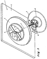
- the diffuser shown in Figure 1 includes a frame 1 to be fixed on a wall or ceiling not shown.
- the frame has a flat part 2 at the periphery and present in the center a frustoconical central part 3.
- This has on the wall side a inlet opening for the air to be diffused which is bordered by a collar 4 coaxial with the inlet opening.
- the piping necessary for the supply in air can be connected to this flange in a manner not illustrated.
- An axis 5, tubular and partially threaded in the example of realization, is supported on the frame 1 by means of a frame support 6, so as to extend in a perpendicular direction at the opening of the diffuser, direction which is illustrated by the dashed line 7, and at be able to be moved relative to the frame along this direction.
- a central deflector 8 of frustoconical shape is fixed to the axis 5 on the side of this one which is opposite the wall.
- the end of the axle, hollow at this point, can be fixed to the central deflector by a simple crimping using a punch.
- This example of realization includes an intermediate deflector 9 of frustoconical shape, which also is fixed to the axis 5, by means of a support frame 10. It is disposed between the frustoconical part 3 of the frame and the central deflector 8. It has, in this example, an inlet opening on the wall side, which allows an air passage in its center, and a diffusion opening of the side opposite the wall, which is larger in diameter than the opening intake.
- the support frame 6 is, in the illustrated embodiment, formed of two parts 11 and 12, stamped in a metal strip.
- they are stamped with identical manner and they each have a flat central part 13 provided in its center with a rounded part 14 in the form of a half-socket, and, at each end of the flat central part 13, a oblique folded part 15, at the free end of which is folded a folded down part 16.
- the two parts stamped in one operation are then arranged symmetrically on either side of a plane of symmetry, by applying their flat central part 13 one against the other and by welding them thus, for example by spot welding.
- Half-sockets 14 assemblies then form a socket 17 complete in which axis 5 can be passed.
- one of the two half-sockets 14 has been very slightly pressed so as to form a tenon 18 which extends radially inside the socket, to a depth approximately equivalent to the depth of the thread presented by the axis 5.
- the axis can be moved axially in the socket 17, by screwing.
- the armature support 10 is also formed of two parts 20 and 21, stamped in a metal strip. These pieces are stamped so identical and each has a flat central part 22, provided in the center with a rounded part 23 in the form of a half-socket. AT each end of this flat part 22 is provided a split part 24 at its free end. In the illustrated embodiment, the parts 24 slits are folded obliquely to the flat central part.
- the two pieces 20 and 21, folded and split by stamping in a single operation, are then arranged symmetrically on either side of a plane of symmetry, applying their central part plane 22 against each other and by welding them together, for example by a spot welding.
- the assembled half-sockets 23 then form a socket 25 complete in which the axis 5 can be passed and fixed, by example by welding or pinching.
- Axis 5 can also be previously arranged between the two half-sockets of the parts stamped, before welding, and thus be fixed directly to the reinforcement of support.
- the method of manufacturing a diffuser according to the invention is therefore implemented in the manner next.
- the partially threaded axis 5 is fixed to the central deflector by example by crimping, as illustrated in figure 2.
- Strips are folded, cut, split and / or stamped so identical by a single stamping operation in a press current, forming the stamped parts 11 and 12 or respectively 20 and 21. These are then joined together so symmetrical and welded to each other, for example by points.
- the support frame 6 is fixed to the flange 4 of the frame 1 by welding and the support frame 10 is fixed by pinching the edge of the opening intake of the intermediate deflector 9 through the split ends of stamped parts.
- the split parts provided at the ends of the central parts 22 of stamped parts of the support frame 10 extend in the same plan as the central parts. They have been stamped to form two legs 26 and 27 separated by a slot-shaped cutout. A tab 26 of each slotted end is, during stamping, folded in oblique to the rest of the stamped part. The deflector 9 is then applied against the tab 27, of each split end, not folded when stamping. Then the legs 26 of the split ends are folded so as to extend again in the plane of the central part 22, which causes a pinching of the edge of the intake opening of the deflector 9, in the slot formed between the tab 26 and the tab 27.
- this process has the great advantage of ease of handling since it boils down essentially by stamping in a single operation each of the parts of the support frames, which are preferably only in number of two for each reinforcement, and by the welding of these between them.
- the fixing of these support frames to the other parts provides for a simple welding and / or pinching. Since these operations do not do not require the acquisition of special equipment, but only very common welding presses and stations and that the material first used, whether metal bands or strips for the armatures or a threaded tube for the axis, is of a very favorable cost, one obtains a very efficient manufacturing process from a cost point of view. This process also allows, by its automation, an acceleration notable for the rate of assembly.
Landscapes
- Engineering & Computer Science (AREA)
- Chemical & Material Sciences (AREA)
- Combustion & Propulsion (AREA)
- Mechanical Engineering (AREA)
- General Engineering & Computer Science (AREA)
- Duct Arrangements (AREA)
- Structures Of Non-Positive Displacement Pumps (AREA)
- Macromolecular Compounds Obtained By Forming Nitrogen-Containing Linkages In General (AREA)
- Automatic Assembly (AREA)
Claims (14)
- Strömungsverteiler für die Luftklimatisierung in Räumen, welcher aufweist:einen Rahmen (1) zur Befestigung an einer Wand und mit einem mittigen kegelstumpfförmigen Teil (3), der aus einer ersten zur Wand hin weisenden Seite eine Eintrittsöffnung für die zu verteilende Luft aufweist und aus einer zweiten der Wand entgegengesetzten Seite eine Verteilungsöffnung mit größerer Abmessung als die Eintrittsöffnung besitzt,eine Achse (5), die mittels einer an dem Rahmen (1) befestigten ersten Stützarmatur (6) in der Mitte des mittigen kegelstumpfförmigen Teils (3) derart abgestützt ist, dass sie sich entlang einer Richtung (7) senkrecht zur Verteilungsöffnung erstreckt und bezüglich des Rahmens (1) entlang dieser senkrechten Richtung verschoben werden kann, undeine mittige Ablenkvorrichtung (8), die entgegengesetzt zur Wand an der Achse (5) befestigt ist,wobei die erste Stützarmatur (6) aus ersten gestanzten und/oder geprägten Teilen (11, 12) gebildet ist, die untereinander verschweißt sind, und mit Haltemitteln (18) ausgestattet ist, die mit der Achse (5) zusammenwirken, um die genannte Verschiebung zu ermöglichen,dadurch gekennzeichnet, dass die Achse (5) zumindest teilweise mit einem Gewinde versehen ist, dass die mit der Achse zusammenwirkenden Haltemittel (18) eine Verschiebung der Achse bezüglich des Rahmens (11) durch Festschrauben/Losschrauben ermöglichen, und dass die Ablenkvorrichtung außerdemmindestens eine kegelförmige Zwischen-Ablenkvorrichtung (9) aufweist, die an der Achse zwischen dem kegelstumpfförmigen Teil (3) des Rahmens und der mittigen Ablenkvorrichtung (8) mittels einer zweiten Stützarmatur (10) befestigt ist, undwobei jede zweite der genannten Stützarmaturen (10) aus zweiten gestanzten und/oder geprägten Teilen (20, 21) gebildet ist, die untereinander verschweißt sind.
- Strömungsverteiler nach Anspruch 1, dadurch gekennzeichnet, dass die erste Stützarmatur (6) durch Schweißen an dem Rahmen (1) befestigt ist.
- Strömungsverteiler nach Anspruch 2, dadurch gekennzeichnet, dass die erste Stützarmatur (6) aus zwei ersten gestanzten und/oder geprägten identischen Metallbändern (11, 12) gebildet ist, die jeweils einen ersten ebenen mittigen Teil (13) aufweisen, der in der Mitte mit einem ersten abgerundeten Teil (14) in Form einer Halbhülse versehen ist; einen an jedem der Enden des ebenen mittigen Teils (13) schräg gefalteten Teil (15) aufweisen und an den freien Enden jedes der schrägen Teile (15) einen umgeschlagenen Teil (16) aufweisen; dass die zwei ersten Metallbänder (11, 12) über ihren ersten ebenen mittigen Teil (13) aneinander geschweißt sind, wobei sie beiderseits einer ersten Symmetrieebene symmetrisch angeordnet sind, so dass eine erste vollständige Hülse (17) mit Hilfe ihrer zusammengebauten Halbhülsen gebildet wird; und dass die umgeschlagenen Teile (16) an einem Kragen (4) angeschweißt sind, der durch den mittigen kegelstumpfförmigen Teil (3) des Rahmens (1) wandseitig gebildet ist.
- Strömungsverteiler nach einem der Ansprüche 1 bis 3, dadurch gekennzeichnet, dass jede der mindestens einen zweiten Stützarmaturen (10) an ihrer entsprechenden konischen Ablenkvorrichtung (9) festgeklemmt ist.
- Strömungsverteiler nach Anspruch 4, dadurch gekennzeichnet, dass jede zweite Stützarmatur (10) aus zwei identischen zweiten gestanzten und/oder geprägten Metallbändern (20, 21) gebildet ist, die jeweils einen zweiten ebenen mittigen Teil (22) aufweisen, der in der Mitte mit einem zweiten abgerundeten Teil (23) in Form einer Halbhülse versehen ist; und an jedem der Enden des zweiten ebenen mittigen Teils (22) einen Teil mit gespaltenem freien Ende (24) aufweisen; und dass die beiden zweiten identischen Metallbänder (20, 21) über ihren zweiten ebenen mittigen Teil (22) aneinandergeschweißt sind, wobei sie beiderseits einer zweiten Symmetrieebene symmetrisch angeordnet sind, so dass eine zweite vollständige Hülse (25) mit Hilfe ihrer zusammengebauten Halbhülsen gebildet wird; und dass die gespaltenen freien Enden an einem Rand einer mittigen Öffnung festgeklemmt sind, die jede Zwischen-Ablenkvorrichtung (9) aufweist.
- Strömungsverteiler nach Anspruch 5, dadurch gekennzeichnet, dass die Achse (5) auf die mittige Ablenkvorrichtung (8) aufgequetscht ist, und dass sie in der Hülse (25) jeder Zwischen-Ablenkvorrichtung (9) festgelegt ist.
- Strömungsverteiler nach einem der Ansprüche 3 bis 6, dadurch gekennzeichnet, dass die Haltemittel (18), die mit der Achse zusammenwirken, um ihre Verschiebung bezüglich des Rahmens (1) durch Schrauben/Losschrauben zu ermöglichen, im Innern der ersten Hülse (17) angeordnet sind.
- Strömungsverteiler nach Anspruch 7, dadurch gekennzeichnet, dass die Haltemittel eine Nase (18) aufweisen, die sich radial ins Innere der ersten Hülse (17) derart erstreckt, dass sie in einem Gewinde der Achse (5) gleiten kann.
- Strömungsverteiler nach Anspruch 8, dadurch gekennzeichnet, dass das Gewinde eine Aussparung (19) aufweist, in welche die Nase (18) durch Schwerkraft eindringen kann, wenn sie sich an der Aussparung vorbeibewegt, so dass eine weitere Verschiebung der Achse blockiert wird und eine weitere Verschiebung nur nach einem Herausnehmen der Nase aus der Aussparung ermöglicht wird.
- Verfahren zum Herstellen eines Strömungsverteilers nach einem der Ansprüche 1 bis 9, dadurch gekennzeichnet, dass es die folgenden Schritte aufweist:dadurch gekennzeichnet, dass die Achse zumindest teilweise mit einem Gewinde versehen ist und dass das Verfahren außerdem die folgenden Schritte aufweist:Befestigen der Achse auf der mittigen Ablenkvorrichtung,Stanzen und/oder Prägen der ersten Teile, die zum Bilden der ersten Stützarmatur bestimmt sind,Verschweißen der ersten gestanzten Teile untereinander, um die erste Stützarmatur zu bilden, undBefestigen der ersten Stützarmatur auf dem Rahmen,Anordnen von Haltemitteln aus mindestens einem der ersten Teile, die zum Bilden der ersten Stützarmatur bestimmt sind, wobei die Haltemittel mit der Achse zusammenwirken können, indem sie ihre Verschiebung bezüglich des Rahmens durch Schrauben/Losschrauben gestatten,Stanzen und/oder Prägen der zweiten Teile, die zum Bilden jeder zweiten Stützarmatur bestimmt sind,Verschweißen der gestanzten und/oder geprägten zweiten Teile untereinander, um jede zweite Stützarmatur zu bilden,Befestigen jeder zweiten Stützarmatur auf der Achse und auf einer entsprechenden Zwischen-Ablenkvorrichtung, undAnordnen der mit der mittigen Ablenkvorrichtung ausgestatteten Achse und jeder mit einer entsprechenden Zwischen-Ablenkvorrichtung versehenen zweiten Stützarmatur in der ersten Stützarmatur durch Schrauben/Losschrauben.
- Verfahren nach Anspruch 10, dadurch gekennzeichnet, dass es ein Befestigen der Achse auf der mittigen Ablenkvorrichtung durch Aufquetschen aufweist.
- Verfahren nach einem der Ansprüche 10 und 11, dadurch gekennzeichnet, dass es ein Befestigen der ersten Stützarmatur auf dem Rahmen durch Schweißen aufweist.
- Verfahren nach einem der Ansprüche 10 bis 12, dadurch gekennzeichnet, dass es während des Stanzens bzw. Prägens der genannten zweiten Teile ein derartiges Ausschneiden aufweist, dass diese ein gespaltenes freies Ende haben, und nach dem Stanzen bzw. Prägen ein Befestigen jeder zweiten Stützarmatur auf einer konischen Zwischen-Ablenkvorrichtung aufweist, indem ein Rand einer mittigen Öffnung davon mittels ihres gespaltenen Endes festgeklemmt wird.
- Verfahren nach einem der Ansprüche 10 bis 13, dadurch gekennzeichnet, dass die Anordnung der Achse in der ersten Stützarmatur ein Festschrauben der Achse in einer Hülse aufweist, die auf der ersten Stützarmatur durch Stanzen bzw. Prägen vorgesehen ist, so dass die mit dem Gewinde der Achse zusammenwirkenden Haltemittel ins Innere der Hülse gelangen, um das Schrauben zu ermöglichen.
Applications Claiming Priority (2)
| Application Number | Priority Date | Filing Date | Title |
|---|---|---|---|
| BE9900476A BE1012783A3 (fr) | 1999-07-12 | 1999-07-12 | Diffuseur pour le conditionnement d'air et son procede de fabrication. |
| BE9900476 | 1999-07-12 |
Publications (2)
| Publication Number | Publication Date |
|---|---|
| EP1069382A1 EP1069382A1 (de) | 2001-01-17 |
| EP1069382B1 true EP1069382B1 (de) | 2004-11-24 |
Family
ID=3891999
Family Applications (1)
| Application Number | Title | Priority Date | Filing Date |
|---|---|---|---|
| EP00870157A Expired - Lifetime EP1069382B1 (de) | 1999-07-12 | 2000-07-10 | Luftstromverteiler für Klimaanlage und dessen Herstellungsverfahren |
Country Status (5)
| Country | Link |
|---|---|
| EP (1) | EP1069382B1 (de) |
| AT (1) | ATE283459T1 (de) |
| BE (1) | BE1012783A3 (de) |
| DE (1) | DE60016100T2 (de) |
| ES (1) | ES2231149T3 (de) |
Family Cites Families (3)
| Publication number | Priority date | Publication date | Assignee | Title |
|---|---|---|---|---|
| US3103869A (en) * | 1961-08-29 | 1963-09-17 | John P Dry | Adjustable air diffuser and damper |
| IT1061921B (it) * | 1976-06-23 | 1983-04-30 | Lolli & C Spa | Perfezionamento nei diffusori per impianti di condizionamento d aria |
| US4714009A (en) * | 1986-08-04 | 1987-12-22 | Philips Industries Inc. | Ceiling air diffuser |
-
1999
- 1999-07-12 BE BE9900476A patent/BE1012783A3/fr not_active IP Right Cessation
-
2000
- 2000-07-10 ES ES00870157T patent/ES2231149T3/es not_active Expired - Lifetime
- 2000-07-10 AT AT00870157T patent/ATE283459T1/de not_active IP Right Cessation
- 2000-07-10 DE DE60016100T patent/DE60016100T2/de not_active Expired - Lifetime
- 2000-07-10 EP EP00870157A patent/EP1069382B1/de not_active Expired - Lifetime
Also Published As
| Publication number | Publication date |
|---|---|
| ES2231149T3 (es) | 2005-05-16 |
| DE60016100T2 (de) | 2005-11-10 |
| DE60016100D1 (de) | 2004-12-30 |
| BE1012783A3 (fr) | 2001-03-06 |
| EP1069382A1 (de) | 2001-01-17 |
| ATE283459T1 (de) | 2004-12-15 |
Similar Documents
| Publication | Publication Date | Title |
|---|---|---|
| FR2619256A1 (fr) | Borne de contact electrique et procede de fabrication d'une telle borne | |
| EP0236185B1 (de) | Vorrichtung zum Befestigen einer Kopfstütze auf einen Fahrzeugsitz | |
| FR3066240A1 (fr) | Support et ensemble support | |
| EP1988001B1 (de) | Durch vormontierte Unterelemente stapelbare Schubkarre oder Ähnliches | |
| EP0020241A1 (de) | Verbindungsvorrichtung für isolierte elektrische Leiter | |
| EP1069382B1 (de) | Luftstromverteiler für Klimaanlage und dessen Herstellungsverfahren | |
| FR2752886A1 (fr) | Procede d'assemblage de deux toles l'une sur l'autre ; assemblage ainsi obtenu | |
| FR2550110A1 (fr) | Procede de realisation d'un collet double embouti et piece a collet double ainsi obtenue | |
| EP0653255B1 (de) | Neuer nietartiger Verbindungspunkt für Bleche durch Kaltfliessen und Werkzeugmaschine zum Durchführen eines solchen Verbindungspunktes | |
| EP1741938B1 (de) | Käfiganordnung für eine Käfigmutter | |
| FR2469307A2 (fr) | Dispositif d'articulation de pare-soleil | |
| EP0301988B1 (de) | Vorrichtung zur Verbindung von zwei Trägern eines Gerüstes in der Höhe des Firstes zum Herstellen von Rahmen und Bauskonstruktionen | |
| EP0301987A1 (de) | Vorrichtung zur Verbindung eines Trägers eines Gerüstes mit einer Stütze zum Herstellen von Gerippen und Baukonstruktion | |
| EP0508850B1 (de) | Reduzierzange für Rohre und dergleichen | |
| EP0878353B1 (de) | Vorrichtung zur vorübergehenden Befestigung einer Beleuchtungs- oder Signaleinrichtung auf der Karosserie eines Kraftfahrzeuges | |
| EP0626533A1 (de) | Halteschelle auf einer Stütze für ein Rohr oder dergleichen | |
| FR2645121A1 (fr) | Couvercle a arracher en particulier pour boite metallique | |
| FR2936845A1 (fr) | Cage d'ecrou | |
| FR2597269A1 (fr) | Connecteur electrique, notamment pour plot de batterie et procede de fabrication d'un tel connecteur | |
| EP0095964A1 (de) | Kupplungsring hergestellt durch Pressen und Falten einer Platte | |
| FR2914969A1 (fr) | Biellette avant de berceau pour vehicule automobile. | |
| FR2653502A1 (fr) | Element tubulaire de renfort et procede pour sa fabrication. | |
| EP0269539A2 (de) | Lösbare Schnellverbindung zwischen einer Glühbirne und ihrer Fassung | |
| FR2621360A1 (fr) | Montage d'un axe entre deux parois | |
| EP2913538A1 (de) | Perfektionierter, mit Kippmechanismus ausgestatter Bolzen und Feststellorgan hierfür |
Legal Events
| Date | Code | Title | Description |
|---|---|---|---|
| PUAI | Public reference made under article 153(3) epc to a published international application that has entered the european phase |
Free format text: ORIGINAL CODE: 0009012 |
|
| AK | Designated contracting states |
Kind code of ref document: A1 Designated state(s): AT BE CH CY DE DK ES FI FR GB GR IE IT LI LU MC NL PT SE |
|
| AX | Request for extension of the european patent |
Free format text: AL;LT;LV;MK;RO;SI |
|
| 17P | Request for examination filed |
Effective date: 20010530 |
|
| AKX | Designation fees paid |
Free format text: AT BE CH CY DE DK ES FI FR GB GR IE IT LI LU MC NL PT SE |
|
| 17Q | First examination report despatched |
Effective date: 20030820 |
|
| GRAP | Despatch of communication of intention to grant a patent |
Free format text: ORIGINAL CODE: EPIDOSNIGR1 |
|
| GRAS | Grant fee paid |
Free format text: ORIGINAL CODE: EPIDOSNIGR3 |
|
| GRAA | (expected) grant |
Free format text: ORIGINAL CODE: 0009210 |
|
| AK | Designated contracting states |
Kind code of ref document: B1 Designated state(s): AT BE CH CY DE DK ES FI FR GB GR IE IT LI LU MC NL PT SE |
|
| PG25 | Lapsed in a contracting state [announced via postgrant information from national office to epo] |
Ref country code: FI Free format text: LAPSE BECAUSE OF FAILURE TO SUBMIT A TRANSLATION OF THE DESCRIPTION OR TO PAY THE FEE WITHIN THE PRESCRIBED TIME-LIMIT Effective date: 20041124 Ref country code: AT Free format text: LAPSE BECAUSE OF FAILURE TO SUBMIT A TRANSLATION OF THE DESCRIPTION OR TO PAY THE FEE WITHIN THE PRESCRIBED TIME-LIMIT Effective date: 20041124 Ref country code: IE Free format text: LAPSE BECAUSE OF FAILURE TO SUBMIT A TRANSLATION OF THE DESCRIPTION OR TO PAY THE FEE WITHIN THE PRESCRIBED TIME-LIMIT Effective date: 20041124 |
|
| REG | Reference to a national code |
Ref country code: GB Ref legal event code: FG4D Free format text: NOT ENGLISH |
|
| REG | Reference to a national code |
Ref country code: CH Ref legal event code: EP |
|
| REF | Corresponds to: |
Ref document number: 60016100 Country of ref document: DE Date of ref document: 20041230 Kind code of ref document: P |
|
| REG | Reference to a national code |
Ref country code: IE Ref legal event code: FG4D Free format text: FRENCH |
|
| PG25 | Lapsed in a contracting state [announced via postgrant information from national office to epo] |
Ref country code: GR Free format text: LAPSE BECAUSE OF FAILURE TO SUBMIT A TRANSLATION OF THE DESCRIPTION OR TO PAY THE FEE WITHIN THE PRESCRIBED TIME-LIMIT Effective date: 20050224 Ref country code: DK Free format text: LAPSE BECAUSE OF FAILURE TO SUBMIT A TRANSLATION OF THE DESCRIPTION OR TO PAY THE FEE WITHIN THE PRESCRIBED TIME-LIMIT Effective date: 20050224 Ref country code: SE Free format text: LAPSE BECAUSE OF FAILURE TO SUBMIT A TRANSLATION OF THE DESCRIPTION OR TO PAY THE FEE WITHIN THE PRESCRIBED TIME-LIMIT Effective date: 20050224 |
|
| GBT | Gb: translation of ep patent filed (gb section 77(6)(a)/1977) |
Effective date: 20050214 |
|
| REG | Reference to a national code |
Ref country code: ES Ref legal event code: FG2A Ref document number: 2231149 Country of ref document: ES Kind code of ref document: T3 |
|
| REG | Reference to a national code |
Ref country code: IE Ref legal event code: FD4D |
|
| PG25 | Lapsed in a contracting state [announced via postgrant information from national office to epo] |
Ref country code: LU Free format text: LAPSE BECAUSE OF NON-PAYMENT OF DUE FEES Effective date: 20050710 Ref country code: CY Free format text: LAPSE BECAUSE OF FAILURE TO SUBMIT A TRANSLATION OF THE DESCRIPTION OR TO PAY THE FEE WITHIN THE PRESCRIBED TIME-LIMIT Effective date: 20050710 |
|
| PG25 | Lapsed in a contracting state [announced via postgrant information from national office to epo] |
Ref country code: CH Free format text: LAPSE BECAUSE OF NON-PAYMENT OF DUE FEES Effective date: 20050731 Ref country code: LI Free format text: LAPSE BECAUSE OF NON-PAYMENT OF DUE FEES Effective date: 20050731 Ref country code: MC Free format text: LAPSE BECAUSE OF NON-PAYMENT OF DUE FEES Effective date: 20050731 Ref country code: BE Free format text: LAPSE BECAUSE OF NON-PAYMENT OF DUE FEES Effective date: 20050731 |
|
| PLBE | No opposition filed within time limit |
Free format text: ORIGINAL CODE: 0009261 |
|
| STAA | Information on the status of an ep patent application or granted ep patent |
Free format text: STATUS: NO OPPOSITION FILED WITHIN TIME LIMIT |
|
| 26N | No opposition filed |
Effective date: 20050825 |
|
| REG | Reference to a national code |
Ref country code: CH Ref legal event code: PL |
|
| BERE | Be: lapsed |
Owner name: *EURO-REGISTER Effective date: 20050731 |
|
| PG25 | Lapsed in a contracting state [announced via postgrant information from national office to epo] |
Ref country code: PT Free format text: LAPSE BECAUSE OF NON-PAYMENT OF DUE FEES Effective date: 20050424 |
|
| PGFP | Annual fee paid to national office [announced via postgrant information from national office to epo] |
Ref country code: NL Payment date: 20120626 Year of fee payment: 13 |
|
| PGFP | Annual fee paid to national office [announced via postgrant information from national office to epo] |
Ref country code: FR Payment date: 20120706 Year of fee payment: 13 Ref country code: GB Payment date: 20120615 Year of fee payment: 13 |
|
| PGFP | Annual fee paid to national office [announced via postgrant information from national office to epo] |
Ref country code: ES Payment date: 20120726 Year of fee payment: 13 Ref country code: IT Payment date: 20120726 Year of fee payment: 13 Ref country code: DE Payment date: 20120615 Year of fee payment: 13 |
|
| REG | Reference to a national code |
Ref country code: NL Ref legal event code: V1 Effective date: 20140201 |
|
| GBPC | Gb: european patent ceased through non-payment of renewal fee |
Effective date: 20130710 |
|
| REG | Reference to a national code |
Ref country code: DE Ref legal event code: R119 Ref document number: 60016100 Country of ref document: DE Effective date: 20140201 |
|
| REG | Reference to a national code |
Ref country code: FR Ref legal event code: ST Effective date: 20140331 |
|
| PG25 | Lapsed in a contracting state [announced via postgrant information from national office to epo] |
Ref country code: NL Free format text: LAPSE BECAUSE OF NON-PAYMENT OF DUE FEES Effective date: 20140201 Ref country code: DE Free format text: LAPSE BECAUSE OF NON-PAYMENT OF DUE FEES Effective date: 20140201 Ref country code: GB Free format text: LAPSE BECAUSE OF NON-PAYMENT OF DUE FEES Effective date: 20130710 |
|
| PG25 | Lapsed in a contracting state [announced via postgrant information from national office to epo] |
Ref country code: FR Free format text: LAPSE BECAUSE OF NON-PAYMENT OF DUE FEES Effective date: 20130731 Ref country code: IT Free format text: LAPSE BECAUSE OF NON-PAYMENT OF DUE FEES Effective date: 20130710 |
|
| REG | Reference to a national code |
Ref country code: ES Ref legal event code: FD2A Effective date: 20141009 |
|
| PG25 | Lapsed in a contracting state [announced via postgrant information from national office to epo] |
Ref country code: ES Free format text: LAPSE BECAUSE OF NON-PAYMENT OF DUE FEES Effective date: 20130711 |