EP1069382B1 - Air diffuser for air conditioning and a manufacturing method for the same - Google Patents
Air diffuser for air conditioning and a manufacturing method for the same Download PDFInfo
- Publication number
- EP1069382B1 EP1069382B1 EP00870157A EP00870157A EP1069382B1 EP 1069382 B1 EP1069382 B1 EP 1069382B1 EP 00870157 A EP00870157 A EP 00870157A EP 00870157 A EP00870157 A EP 00870157A EP 1069382 B1 EP1069382 B1 EP 1069382B1
- Authority
- EP
- European Patent Office
- Prior art keywords
- spindle
- support armature
- frame
- central
- baffle
- Prior art date
- Legal status (The legal status is an assumption and is not a legal conclusion. Google has not performed a legal analysis and makes no representation as to the accuracy of the status listed.)
- Expired - Lifetime
Links
- 238000004519 manufacturing process Methods 0.000 title claims abstract description 7
- 238000004378 air conditioning Methods 0.000 title claims description 5
- 238000003466 welding Methods 0.000 claims description 19
- 238000000034 method Methods 0.000 claims description 13
- 239000002184 metal Substances 0.000 claims description 12
- 238000009792 diffusion process Methods 0.000 claims description 7
- 238000002788 crimping Methods 0.000 claims description 4
- 230000005484 gravity Effects 0.000 claims description 2
- 238000007373 indentation Methods 0.000 claims 3
- 230000000903 blocking effect Effects 0.000 claims 1
- 238000005520 cutting process Methods 0.000 claims 1
- 238000007664 blowing Methods 0.000 description 3
- 238000006073 displacement reaction Methods 0.000 description 3
- 206010044625 Trichorrhexis Diseases 0.000 description 2
- 238000005553 drilling Methods 0.000 description 2
- 235000021183 entrée Nutrition 0.000 description 2
- 230000002787 reinforcement Effects 0.000 description 2
- 230000001133 acceleration Effects 0.000 description 1
- 230000000712 assembly Effects 0.000 description 1
- 238000000429 assembly Methods 0.000 description 1
- 239000000470 constituent Substances 0.000 description 1
- 238000007599 discharging Methods 0.000 description 1
- 230000000694 effects Effects 0.000 description 1
- 230000002349 favourable effect Effects 0.000 description 1
- 230000014759 maintenance of location Effects 0.000 description 1
- 239000000463 material Substances 0.000 description 1
- 238000012986 modification Methods 0.000 description 1
- 230000004048 modification Effects 0.000 description 1
- 238000004801 process automation Methods 0.000 description 1
- 239000011265 semifinished product Substances 0.000 description 1
Images

Classifications
-
- F—MECHANICAL ENGINEERING; LIGHTING; HEATING; WEAPONS; BLASTING
- F24—HEATING; RANGES; VENTILATING
- F24F—AIR-CONDITIONING; AIR-HUMIDIFICATION; VENTILATION; USE OF AIR CURRENTS FOR SCREENING
- F24F13/00—Details common to, or for air-conditioning, air-humidification, ventilation or use of air currents for screening
- F24F13/02—Ducting arrangements
- F24F13/06—Outlets for directing or distributing air into rooms or spaces, e.g. ceiling air diffuser
- F24F13/062—Outlets for directing or distributing air into rooms or spaces, e.g. ceiling air diffuser having one or more bowls or cones diverging in the flow direction
Definitions
- circular diffusers consisting of a outer envelope, fixed to the ceiling, and provided with deflection to direct the air supply according to the position of these. By adjusting the position of these elements relative to the outer casing, one can thus obtain for example a blowing horizontal which keeps the air to a certain extent on the ceiling or a vertical blowing, with shower effect, as well as blowing intermediate.
- All known diffusers have the disadvantage of being made up of a very large number of parts, necessary in particular for assembly between the outer casing and the various elements air deflection as well as to allow adjustment of the air supply the air.
- the assembly of known diffusers generally requires a large number of manual operations, such as drilling, bolting or riveting, which increases the cost of these diffusers.
- no safety measures are designed to prevent unintentional detachment of parts, which can lead to accidents, especially during assembly.
- the object of the present invention is to overcome these disadvantages and to make a diffuser suitable for air conditioning with a minimum number of constituent parts, by means basic and inexpensive operations, performed on machines traditional of a company in the metal manufacturing sector, these parts being themselves made from semi-finished products extremely simple and inexpensive.
- the first support frame is also welded to the frame.
- the first support frame is formed of two first metal bands identical stamps which each have a first part flat central unit provided in the center with a first part rounded in shape half-sleeve, a part folded obliquely at each end of the first flat central part and a part folded down at the ends free of each oblique part, the first two bands metallic being welded to each other by their first central part plane while being arranged symmetrically on either side of a first plane of symmetry, so as to form a first complete socket at using their assembled half-sockets, the folded parts being welded to a flange presented by the frustoconical central part of the frame, on the wall side.
- each second support frame is formed of two second identical stamped metal bands, each with a second flat central part provided in the center with a second part rounded in the shape of a half-socket, and at each end of the second flat central part, a split free end part, the two identical second metal strips being welded one to the other the other by their second flat central part being arranged symmetrically on either side of a second plane of symmetry, of so as to form a second complete socket using their half-sockets assembled, said split free ends being pinched on an edge of a central opening presented by each deflector intermediate.
- the means of restraint cooperating with the axis to allow its displacement relative to the frame are located inside said first socket.
- the present invention also relates to a method of manufacture of a diffuser.
- the process does not include drilling, no bolting, no riveting.
- the pieces forming the frames of supports can be simple metal bands which are stamped to the press to take their final shape and which are then welded between them, and possibly further welded to the frame in the case of the first support frame. Extensive process automation is thus obtained by using current equipment in the workshop.
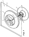
- the diffuser shown in Figure 1 includes a frame 1 to be fixed on a wall or ceiling not shown.
- the frame has a flat part 2 at the periphery and present in the center a frustoconical central part 3.
- This has on the wall side a inlet opening for the air to be diffused which is bordered by a collar 4 coaxial with the inlet opening.
- the piping necessary for the supply in air can be connected to this flange in a manner not illustrated.
- An axis 5, tubular and partially threaded in the example of realization, is supported on the frame 1 by means of a frame support 6, so as to extend in a perpendicular direction at the opening of the diffuser, direction which is illustrated by the dashed line 7, and at be able to be moved relative to the frame along this direction.
- a central deflector 8 of frustoconical shape is fixed to the axis 5 on the side of this one which is opposite the wall.
- the end of the axle, hollow at this point, can be fixed to the central deflector by a simple crimping using a punch.
- This example of realization includes an intermediate deflector 9 of frustoconical shape, which also is fixed to the axis 5, by means of a support frame 10. It is disposed between the frustoconical part 3 of the frame and the central deflector 8. It has, in this example, an inlet opening on the wall side, which allows an air passage in its center, and a diffusion opening of the side opposite the wall, which is larger in diameter than the opening intake.
- the support frame 6 is, in the illustrated embodiment, formed of two parts 11 and 12, stamped in a metal strip.
- they are stamped with identical manner and they each have a flat central part 13 provided in its center with a rounded part 14 in the form of a half-socket, and, at each end of the flat central part 13, a oblique folded part 15, at the free end of which is folded a folded down part 16.
- the two parts stamped in one operation are then arranged symmetrically on either side of a plane of symmetry, by applying their flat central part 13 one against the other and by welding them thus, for example by spot welding.
- Half-sockets 14 assemblies then form a socket 17 complete in which axis 5 can be passed.
- one of the two half-sockets 14 has been very slightly pressed so as to form a tenon 18 which extends radially inside the socket, to a depth approximately equivalent to the depth of the thread presented by the axis 5.
- the axis can be moved axially in the socket 17, by screwing.
- the armature support 10 is also formed of two parts 20 and 21, stamped in a metal strip. These pieces are stamped so identical and each has a flat central part 22, provided in the center with a rounded part 23 in the form of a half-socket. AT each end of this flat part 22 is provided a split part 24 at its free end. In the illustrated embodiment, the parts 24 slits are folded obliquely to the flat central part.
- the two pieces 20 and 21, folded and split by stamping in a single operation, are then arranged symmetrically on either side of a plane of symmetry, applying their central part plane 22 against each other and by welding them together, for example by a spot welding.
- the assembled half-sockets 23 then form a socket 25 complete in which the axis 5 can be passed and fixed, by example by welding or pinching.
- Axis 5 can also be previously arranged between the two half-sockets of the parts stamped, before welding, and thus be fixed directly to the reinforcement of support.
- the method of manufacturing a diffuser according to the invention is therefore implemented in the manner next.
- the partially threaded axis 5 is fixed to the central deflector by example by crimping, as illustrated in figure 2.
- Strips are folded, cut, split and / or stamped so identical by a single stamping operation in a press current, forming the stamped parts 11 and 12 or respectively 20 and 21. These are then joined together so symmetrical and welded to each other, for example by points.
- the support frame 6 is fixed to the flange 4 of the frame 1 by welding and the support frame 10 is fixed by pinching the edge of the opening intake of the intermediate deflector 9 through the split ends of stamped parts.
- the split parts provided at the ends of the central parts 22 of stamped parts of the support frame 10 extend in the same plan as the central parts. They have been stamped to form two legs 26 and 27 separated by a slot-shaped cutout. A tab 26 of each slotted end is, during stamping, folded in oblique to the rest of the stamped part. The deflector 9 is then applied against the tab 27, of each split end, not folded when stamping. Then the legs 26 of the split ends are folded so as to extend again in the plane of the central part 22, which causes a pinching of the edge of the intake opening of the deflector 9, in the slot formed between the tab 26 and the tab 27.
- this process has the great advantage of ease of handling since it boils down essentially by stamping in a single operation each of the parts of the support frames, which are preferably only in number of two for each reinforcement, and by the welding of these between them.
- the fixing of these support frames to the other parts provides for a simple welding and / or pinching. Since these operations do not do not require the acquisition of special equipment, but only very common welding presses and stations and that the material first used, whether metal bands or strips for the armatures or a threaded tube for the axis, is of a very favorable cost, one obtains a very efficient manufacturing process from a cost point of view. This process also allows, by its automation, an acceleration notable for the rate of assembly.
Landscapes
- Engineering & Computer Science (AREA)
- Chemical & Material Sciences (AREA)
- Combustion & Propulsion (AREA)
- Mechanical Engineering (AREA)
- General Engineering & Computer Science (AREA)
- Duct Arrangements (AREA)
- Structures Of Non-Positive Displacement Pumps (AREA)
- Automatic Assembly (AREA)
- Macromolecular Compounds Obtained By Forming Nitrogen-Containing Linkages In General (AREA)
Abstract
Description
La présente invention a pour objet un diffuseur pour le conditionnement d'air destiné à l'alimentation et à l'évacuation de l'air, notamment par le plafond, dans des locaux, en particulier de grand volume, comprenant :
- un cadre (1) à fixer sur une paroi et présentant une partie centrale tronconique (3) qui, d'un premier côté tourné vers la paroi, comporte une ouverture d'entrée pour l'air à diffuser et, d'un deuxième côté opposé à la paroi, présente une ouverture de diffusion de dimension supérieure à l'ouverture d'entrée,
- un axe (5) qui est, par une première armature de support (6) fixée au cadre (1), supporté au centre de ladite partie centrale tronconique (3) de manière à s'étendre suivant une direction (7) perpendiculaire à l'ouverture de diffusion et à pouvoir être déplacé par rapport au cadre (1) le long de cette direction perpendiculaire, et
- un déflecteur central (8), qui est fixé à l'axe (5) à l'opposé de la paroi,
- ladite première armature de support (6) étant formée de premières pièces estampées (11, 12), soudées entre elles, et étant pourvue de moyens de retenue (18) coopérant avec l'axe (5) pour permettre son déplacement susdit (v. par exemple US-A-3.103.869).
- a frame (1) to be fixed on a wall and having a frustoconical central part (3) which, on a first side facing the wall, has an inlet opening for the air to be diffused and, on a second side opposite the wall, has a diffusion opening of dimension greater than the entry opening,
- an axis (5) which is, by a first support frame (6) fixed to the frame (1), supported at the center of said frustoconical central part (3) so as to extend in a direction (7) perpendicular to the diffusion opening and being able to be moved relative to the frame (1) along this perpendicular direction, and
- a central deflector (8), which is fixed to the axis (5) opposite the wall,
- said first support frame (6) being formed of first stamped parts (11, 12), welded together, and being provided with retaining means (18) cooperating with the axis (5) to allow its aforesaid movement (see. for example US-A-3,103,869).
On connaít des diffuseurs rectangulaires à plusieurs déflecteurs fixes, non réglables (v. par exemple US-A-4.714.009). We know rectangular diffusers with several fixed, non-adjustable deflectors (see for example US-A-4,714.009).
On connaít aussi des diffuseurs circulaires constitués d'une enveloppe extérieure, fixée au plafond, et pourvus d'éléments de déviation permettant d'orienter le soufflage de l'air en fonction de la position de ceux-ci. Par réglage de la position de ces éléments par rapport à l'enveloppe extérieure, on peut ainsi obtenir par exemple un soufflage horizontal qui maintient dans une certaine mesure l'air au plafond ou un soufflage vertical, avec effet de douche, ainsi que des soufflages intermédiaires.We also know circular diffusers consisting of a outer envelope, fixed to the ceiling, and provided with deflection to direct the air supply according to the position of these. By adjusting the position of these elements relative to the outer casing, one can thus obtain for example a blowing horizontal which keeps the air to a certain extent on the ceiling or a vertical blowing, with shower effect, as well as blowing intermediate.
Tous les diffuseurs connus présentent l'inconvénient d'être constitués d'un très grand nombre de pièces, nécessaires en particulier pour l'assemblage entre l'enveloppe extérieure et les différents éléments de déviation de l'air ainsi que pour permettre un réglage du soufflage de l'air. L'assemblage des diffuseurs connus nécessite généralement un grand nombre d'opérations manuelles, comme des opérations de forage, de boulonnage ou de rivetage, ce qui grève le coût de ces diffuseurs. Par ailleurs, lors du réglage de la position mutuelle entre l'enveloppe extérieure et les éléments de déviation, aucune mesure de sécurité n'est prévue pour empêcher un détachement involontaire des pièces, ce qui peut mener à des accidents notamment au cours du montage.All known diffusers have the disadvantage of being made up of a very large number of parts, necessary in particular for assembly between the outer casing and the various elements air deflection as well as to allow adjustment of the air supply the air. The assembly of known diffusers generally requires a large number of manual operations, such as drilling, bolting or riveting, which increases the cost of these diffusers. Through elsewhere, when adjusting the mutual position between the envelope external and deflection elements, no safety measures are designed to prevent unintentional detachment of parts, which can lead to accidents, especially during assembly.
La présente invention a pour but de surmonter ces inconvénients et de fabriquer un diffuseur adapté au conditionnement d'air présentant un nombre minimal de pièces constitutives, au moyen d'opérations élémentaires et peu coûteuses, réalisables sur des machines traditionnelles d'une entreprise du secteur des fabrications métalliques, ces pièces étant elles-mêmes fabriquées à partir de produits semi-finis extrêmement simples et peu coûteux.The object of the present invention is to overcome these disadvantages and to make a diffuser suitable for air conditioning with a minimum number of constituent parts, by means basic and inexpensive operations, performed on machines traditional of a company in the metal manufacturing sector, these parts being themselves made from semi-finished products extremely simple and inexpensive.
On résout ces problèmes suivant l'invention par un diffuseur pour le conditionnement d'air dans des locaux tel qu'indiqué au début, ce diffuseur étant caractérisé en ce que l'axe est au moins partiellement fileté, en ce que les moyens de retenue coopérant avec l'axe permettent son déplacement par rapport au cadre par vissage/dévissage, et en ce que le diffuseur comprend en outre
- au moins un déflecteur conique intermédiaire, qui est fixé à l'axe entre la partie tronconique du cadre et le déflecteur central par une deuxième armature de support,
- chaque deuxième armature de support susdite étant formée de deuxièmes pièces estampées, soudées entre elles. Un tel diffuseur présente l'avantage de prévoir un assemblage des différents éléments uniquement à l'aide de pièces estampées, soudées entre elles. Ces opérations peuvent donc être effectuées par une presse courante et par un poste de soudure, par exemple par points, à un coût extrêmement faible et avec une main-d'oeuvre réduite.
- at least one intermediate conical deflector, which is fixed to the axis between the frustoconical part of the frame and the central deflector by a second support frame,
- each second aforementioned support frame being formed of second stamped parts, welded together. Such a diffuser has the advantage of providing an assembly of the different elements only using stamped parts, welded together. These operations can therefore be carried out by a standard press and by a welding station, for example by spot welding, at an extremely low cost and with reduced labor.
Avantageusement, la première armature de support est elle aussi soudée au cadre.Advantageously, the first support frame is also welded to the frame.
Suivant une forme de réalisation de l'invention, la première armature de support est formée de deux premières bandes métalliques estampées identiques qui présentent chacune une première partie centrale plane pourvue au centre d'une première partie arrondie en forme de demi-douille, une partie pliée en oblique à chacune des extrémités de la première partie centrale plane et une partie rabattue aux extrémités libres de chacune des parties en oblique, les deux premières bandes métalliques étant soudées l'une à l'autre par leur première partie centrale plane en étant agencées symétriquement de part et d'autre d'un premier plan de symétrie, de manière à former une première douille complète à l'aide de leurs demi-douilles assemblées, les parties rabattues étant soudées à une collerette présentée par la partie centrale tronconique du cadre, du côté paroi.According to an embodiment of the invention, the first support frame is formed of two first metal bands identical stamps which each have a first part flat central unit provided in the center with a first part rounded in shape half-sleeve, a part folded obliquely at each end of the first flat central part and a part folded down at the ends free of each oblique part, the first two bands metallic being welded to each other by their first central part plane while being arranged symmetrically on either side of a first plane of symmetry, so as to form a first complete socket at using their assembled half-sockets, the folded parts being welded to a flange presented by the frustoconical central part of the frame, on the wall side.
Suivant une forme de réalisation avantageuse de l'invention, chaque deuxième armature de support est formée de deux deuxièmes bandes métalliques estampées identiques qui présentent chacune une deuxième partie centrale plane pourvue au centre d'une deuxième partie arrondie en forme de demi-douille, et, à chacune des extrémités de la deuxième partie centrale plane, une partie à extrémité libre fendue, les deux deuxièmes bandes métalliques identiques étant soudées l'une à l'autre par leur deuxième partie centrale plane en étant agencées symétriquement de part et d'autre d'un deuxième plan de symétrie, de manière à former une deuxième douille complète à l'aide de leurs demi-douilles assemblées, lesdites extrémités libres fendues étant pincées sur un bord d'une ouverture centrale présentée par chaque déflecteur intermédiaire.According to an advantageous embodiment of the invention, each second support frame is formed of two second identical stamped metal bands, each with a second flat central part provided in the center with a second part rounded in the shape of a half-socket, and at each end of the second flat central part, a split free end part, the two identical second metal strips being welded one to the other the other by their second flat central part being arranged symmetrically on either side of a second plane of symmetry, of so as to form a second complete socket using their half-sockets assembled, said split free ends being pinched on an edge of a central opening presented by each deflector intermediate.
Suivant une forme perfectionnée de réalisation de l'invention, les moyens de retenue coopérant avec l'axe pour permettre son déplacement par rapport au cadre sont situés à l'intérieur de ladite première douille. According to an improved embodiment of the invention, the means of restraint cooperating with the axis to allow its displacement relative to the frame are located inside said first socket.
D'autres détails et particularités du diffuseur suivant l'invention sont indiqués dans les revendications.Other details and features of the following diffuser the invention are indicated in the claims.
La présente invention concerne également un procédé de fabrication d'un diffuseur.The present invention also relates to a method of manufacture of a diffuser.
Suivant un mode de réalisation de l'invention, le procédé comprend
- une fixation de l'axe sur te déflecteur central,
- un estampage des premières pièces destinées à former la première armature de support,
- un soudage des premières pièces estampées entre elles pour former la première armature de support, et
- une fixation de la première armature de support sur le cadre,
- un agencement, sur au moins l'une des premières pièces destinées à former ladite première armature de support, de moyens de retenue capables de coopérer avec l'axe en permettant son déplacement par rapport au cadre par vissage/dévissage,
- un estampage des deuxièmes pièces destinées à former chaque deuxième armature de support,
- un soudage des deuxièmes pièces estampées entre elles pour former chaque deuxième armature de support,
- une fixation de chaque deuxième armature de support sur l'axe, et sur un déflecteur intermédiaire correspondant,
- un agencement par vissage/dévissage de l'axe muni du déflecteur central et de chaque deuxième armature de support pourvue d'un déflecteur intermédiaire correspondant dans la première armature de support.
- fixing the axle on the central deflector,
- stamping of the first parts intended to form the first support frame,
- welding the first stamped parts together to form the first support frame, and
- fixing the first support frame to the frame,
- an arrangement, on at least one of the first parts intended to form said first support frame, of retaining means capable of cooperating with the axis by allowing its displacement relative to the frame by screwing / unscrewing,
- a stamping of the second parts intended to form each second support frame,
- welding of the second stamped parts together to form each second support frame,
- a fixing of each second support frame on the axis, and on a corresponding intermediate deflector,
- an arrangement by screwing / unscrewing the axis provided with the central deflector and each second support frame provided with a corresponding intermediate deflector in the first support frame.
Comme on peut le constater, le procédé ne comprend ni forage, ni boulonnage, ni rivetage. Les pièces formant les armatures de supports peuvent être de simples bandes métalliques qui sont estampées à la presse pour prendre leur forme définitive et qui sont ensuite soudées entre elles, et éventuellement en outre soudées au cadre dans le cas de la première armature de support. Une automatisation poussée du procédé est ainsi obtenue en faisant appel à un appareillage courant en atelier.As can be seen, the process does not include drilling, no bolting, no riveting. The pieces forming the frames of supports can be simple metal bands which are stamped to the press to take their final shape and which are then welded between them, and possibly further welded to the frame in the case of the first support frame. Extensive process automation is thus obtained by using current equipment in the workshop.
D'autres indications concernant le procédé suivant l'invention apparaissent dans les revendications annexées.Other indications concerning the following process the invention appears in the appended claims.
D'autres détails et particularités de l'invention ressortiront de
la description donnée ci-après, à titre non limitatif, d'un exemple de
réalisation de diffuseur suivant l'invention.
Sur les différents dessins, des éléments identiques ou analogues sont désignés par les mêmes références.In the various drawings, identical elements or analogues are designated by the same references.
Le diffuseur représenté sur la figure 1 comprend un cadre 1 à fixer sur une paroi ou plafond non représenté. Dans l'exemple illustré, le cadre comporte une partie plane 2 en périphérie et présente au centre une partie centrale tronconique 3. Celle-ci présente du côté paroi une ouverture d'entrée pour l'air à diffuser qui est bordée d'une collerette 4 coaxiale à l'ouverture d'entrée. La tuyauterie nécessaire à l'alimentation en air peut se raccorder à cette collerette d'une manière non illustrée.The diffuser shown in Figure 1 includes a frame 1 to be fixed on a wall or ceiling not shown. In the example shown, the frame has a flat part 2 at the periphery and present in the center a frustoconical central part 3. This has on the wall side a inlet opening for the air to be diffused which is bordered by a collar 4 coaxial with the inlet opening. The piping necessary for the supply in air can be connected to this flange in a manner not illustrated.
Un axe 5, tubulaire et partiellement fileté dans l'exemple de
réalisation, est supporté sur le cadre 1 par l'intermédiaire d'une armature
de support 6, de manière à s'étendre suivant une direction perpendiculaire
à l'ouverture du diffuseur, direction qui est illustrée par le trait mixte 7, et à
pouvoir être déplacé par rapport au cadre le long de cette direction.An
Selon l'exemple de réalisation illustré sur la figure 1, un
déflecteur central 8 de forme tronconique est fixé à l'axe 5 du côté de
celui-ci qui est à l'opposé de la paroi. Ainsi qu'il ressort de la figure 2, le
bout de l'axe, creux à cet endroit, peut être fixé au déflecteur central par
un simple sertissage à l'aide d'un poinçon. Cet exemple de réalisation
comprend un déflecteur intermédiaire 9 de forme tronconique, qui lui aussi
est fixé à l'axe 5, par l'intermédiaire d'une armature de support 10. Il est
disposé entre la partie tronconique 3 du cadre et le déflecteur central 8. Il
présente, dans cet exemple, une ouverture d'admission du côté paroi, qui
permet un passage d'air en son centre, et une ouverture de diffusion du
côté opposé à la paroi, qui est de diamètre supérieur à l'ouverture
d'admission.According to the embodiment illustrated in FIG. 1, a
On pourrait bien entendu prévoir plusieurs déflecteurs intermédiaires, de dimensions croissantes ou non.We could of course provide several deflectors intermediate, increasing or not.
Suivant l'invention, l'armature de support 6 est, dans
l'exemple de réalisation illustré, formée de deux pièces 11 et 12,
estampées dans une bande métallique. Ici elles sont estampées de
manière identique et elles présentent chacune une partie centrale plane
13 pourvue en son centre d'une partie arrondie 14 en forme de demi-douille,
et, à chacune des extrémités de la partie centrale plane 13, une
partie pliée en oblique 15, à l'extrémité libre de laquelle est repliée une
partie rabattue 16.According to the invention, the
Les deux pièces estampées en une seule opération sont
alors disposées de manière symétrique de part et d'autre d'un plan de
symétrie, en appliquant leur partie centrale plane 13 l'une contre l'autre et
en les soudant ainsi, par exemple par un soudage par points. Les demi-douilles
14 assemblées forment alors une douille 17 complète dans
laquelle l'axe 5 peut être passé.The two parts stamped in one operation are
then arranged symmetrically on either side of a plane of
symmetry, by applying their flat
Ainsi qu'il ressort de la figure 4, au cours de l'estampage,
une des deux demi-douilles 14 a été très légèrement emboutie de
manière à former un tenon 18 qui s'étend radialement à l'intérieur de la
douille, sur une profondeur qui équivaut approximativement à la
profondeur du filet présenté par l'axe 5. Ainsi, l'axe peut être déplacé
axialement dans la douille 17, par vissage.As can be seen from FIG. 4, during stamping,
one of the two half-
Sur la figure 4, on peut voir à proximité de l'extrémité du filet,
un évidement 19. Lors du dévissage de l'axe, et donc lorsque le déflecteur
intermédiaire 9 et le déflecteur central 8 sont écartés de la partie centrale
tronconique 3 du cadre 1, le tenon pénètre par gravité dans l'évidement
du filet de l'axe 5. De cette manière, il n'est plus possible de continuer à
dévisser l'axe, car le tenon 18 bloque le mouvement de rotation de l'axe 5.
Ainsi, un détachement involontaire de l'axe et des déflecteurs à partir du
cadre 1 est empêché d'une manière simple. Si on désire détacher l'axe 5
de la douille 17, il faut alors soulever légèrement l'axe 5 en direction
axiale et faire sortir le tenon 18 de l'évidement 19 et poursuivre alors le
dévissage jusqu'à ce que le tenon 18 sorte du filet de l'axe 5.In Figure 4, we can see near the end of the net,
a
Sur l'exemple de réalisation illustré sur la figure 1, l'armature
de support 10 est formée elle aussi de deux pièces 20 et 21, estampées
dans une bande métallique. Ces pièces sont estampées de manière
identique et elles présentent chacune une partie centrale plane 22,
pourvue au centre d'une partie arrondie 23 en forme de demi-douille. A
chaque extrémité de cette partie plane 22 est prévue une partie 24 fendue
à son extrémité libre. Dans l'exemple de réalisation illustré, les parties 24
fendues sont pliées en oblique par rapport à la partie centrale plane.In the embodiment illustrated in FIG. 1, the
Les deux pièces 20 et 21, pliées et fendues par estampage
en une seule opération, sont alors disposées de manière symétrique de
part et d'autre d'un plan de symétrie, en appliquant leur partie centrale
plane 22 l'une contre l'autre et en les soudant ainsi, par exemple par un
soudage par points. Les demi-douilles 23 assemblées forment alors une
douille 25 complète dans laquelle l'axe 5 peut être passé et fixé, par
exemple par soudage ou par pinçage. L'axe 5 peut aussi être
préalablement agencé entre les deux demi-douilles des pièces
estampées, avant leur soudage, et être fixé ainsi directement à l'armature
de support.The two
Le procédé de fabrication d'un diffuseur suivant l'invention,
tel qu'illustré sur la figure 1, est donc mis en oeuvre de la manière
suivante. L'axe partiellement fileté 5 est fixé sur le déflecteur central par
exemple par sertissage, comme illustré sur la figure 2. Des bandes
métalliques sont pliées, découpées, fendues et/ou embouties de manière
identique par une seule opération d'estampage dans une presse
courante, en formant les pièces estampées 11 et 12 ou respectivement 20
et 21. Celles-ci sont accolées ensuite l'une à l'autre de manière
symétrique et soudées l'un à l'autre, par exemple par points.The method of manufacturing a diffuser according to the invention,
as illustrated in FIG. 1, is therefore implemented in the manner
next. The partially threaded
Dans l'exemple de réalisation illustré sur la figure 1,
l'armature de support 6 est fixée à la collerette 4 du cadre 1 par soudage
et l'armature de support 10 est fixée par pinçage du bord de l'ouverture
d'admission du déflecteur intermédiaire 9 par l'intermédiaire des
extrémités fendues des pièces estampées.In the embodiment illustrated in FIG. 1,
the
On pourrait bien entendu prévoir l'inverse, c'est-à-dire un
pinçage de l'armature 6 sur le cadre 1 et un soudage de l'armature 10 sur
le déflecteur 9. On pourrait aussi imaginer une fixation identique des deux
armatures.We could of course predict the opposite, that is to say a
pinching the
Dans l'exemple de réalisation représenté sur la figure 3, les
parties fendues prévues aux extrémités des parties centrales 22 des
pièces estampées de l'armature de support 10 s'étendent dans le même
plan que les parties centrales. Elles ont été estampées de façon à former
deux pattes 26 et 27 séparées par une découpe en forme de fente. Une
patte 26 de chaque extrémité fendue est, lors de l'estampage, repliée en
oblique par rapport au reste de la pièce estampée. Le déflecteur 9 est
alors appliqué contre la patte 27, de chaque extrémité fendue, non repliée
lors de l'estampage. Puis les pattes 26 des extrémités fendues sont
repliées de façon à s'étendre à nouveau dans le plan de la partie centrale
22, ce qui provoque un pinçage du bord de l'ouverture d'admission du
déflecteur 9, dans la fente formée entre la patte 26 et la patte 27.In the embodiment shown in Figure 3, the
split parts provided at the ends of the
Comme on le comprendra aisément, ce procédé présente le grand avantage d'une facilité de manipulation puisqu'il se résume essentiellement en l'estampage en une seule opération de chacune des pièces des armatures de support, qui de préférence ne sont qu'au nombre de deux pour chaque armature, et en le soudage de celles-ci entre elles. La fixation de ces armatures de support aux autres pièces prévoit un simple soudage et/ou un pinçage. Etant donné que ces opérations ne nécessitent pas l'acquisition d'appareillages spéciaux, mais uniquement des presses et postes de soudage tout à fait courants et que la matière première utilisée, que ce soit des bandes ou feuillards métalliques pour les armatures ou un tube fileté pour l'axe, est d'un coût très favorable, on obtient un procédé de fabrication très performant au point de vue coût. Ce procédé permet, en outre, par son automatisation, une accélération notable de la cadence d'assemblage.As will be readily understood, this process has the great advantage of ease of handling since it boils down essentially by stamping in a single operation each of the parts of the support frames, which are preferably only in number of two for each reinforcement, and by the welding of these between them. The fixing of these support frames to the other parts provides for a simple welding and / or pinching. Since these operations do not do not require the acquisition of special equipment, but only very common welding presses and stations and that the material first used, whether metal bands or strips for the armatures or a threaded tube for the axis, is of a very favorable cost, one obtains a very efficient manufacturing process from a cost point of view. This process also allows, by its automation, an acceleration notable for the rate of assembly.
Il doit être entendu que la présente invention n'est en aucune façon limitée aux formes de réalisation décrites ci-dessus et que bien des modifications peuvent y être apportées sans sortir du cadre des revendications annexées.It should be understood that the present invention is not in in no way limited to the embodiments described above and that many modifications can be made without departing from the framework of appended claims.
Claims (14)
- Diffuser for air conditioning in premises including:characterised in that the spindle (5) is at least partially threaded, in that the retaining means (18) cooperating with the spindle facilitate its movement relative to the frame (1) by a screwing/unscrewing action, and in that the diffuser additionally includesa frame (1) to be fixed to a wall and presenting a tapering central part (3) which, on a first side facing the wall, incorporates an inlet aperture for the air to be diffused and, on a second side opposite the wall, presents a diffusion aperture of larger dimensions than the inlet aperture,a spindle (5) which is fixed to the frame (1) by means of a first support armature (6), and supported at the centre of said tapering central part (3) so as to extend in a direction (7) perpendicular to the diffusion aperture and capable of being displaced relative to the frame (1) in this perpendicular direction, anda central baffle (8) which is fixed to the spindle (5) opposite the wall,said first support armature (6) being formed from first stamped components (11, 12) welded together, and being provided with retaining means (18) cooperating with the spindle (5) to facilitate its aforementioned movement,at least one intermediate conical baffle (9), which is fixed to the spindle between the tapering part (3) of the frame and the central baffle (8) by a second support armature (10),each aforementioned second support armature (10) being formed from second stamped components (20, 21) welded together.
- Diffuser according to Claim 1, characterised in that the first support armature (6) is attached to the frame (1) by welding.
- Diffuser according to Claim 2, characterised in that the first support armature (6) is formed from two identical first stamped metal strips (11, 12) each of which has a first flat central part (13) provided at the centre with a first rounded part (14) in the form of a half-bushing, a part folded at an oblique angle (15) at each end of the first flat central part (13) and a flanged part (16) at the free ends of each of the oblique parts (15), in that the two first metal strips (11, 12) are welded together by their first flat central part (13) and are arranged symmetrically on either side of a first plane of symmetry so as to form a first complete bushing (17) by means of their assembled half-bushings, and in that the flanged parts (16) are welded to a collar (4) presented by the central tapering part (3) of the frame (1) on the wall side.
- Diffuser according to any of Claims 1 to 3, characterised in that each of said at least one second support armature (10) is clamped to its corresponding conical baffle (9).
- Diffuser according to Claim 4, characterised in that each second support armature (10) is formed from two identical second stamped metal strips (20, 21) each presenting a second flat central part (22) provided at the centre with a second rounded part (23) in the form of a half-bushing, and at each end of the second flat central part (22) a part having a bifurcated free end (24), and in that the two identical second metal strips (20, 21) are welded together by their second flat central part. (22) being arranged symmetrically on either side of a second plane of symmetry so as to form a second complete bushing (25) by means of their assembled half-bushings, and in that said bifurcated free ends are clamped to an edge of a central opening presented by each intermediate baffle (9).
- Diffuser according to Claim 5, characterised in that the spindle (5) is crimped on the central baffle (8) and in that it is captive in the bushing (25) of each intermediate baffle (9).
- Diffuser according to any of Claims 3 to 6, characterised in that the retaining means (18) cooperating with the spindle to facilitate its movement relative to the frame (1) by screwing/unscrewing are located inside the first bushing (17).
- Diffuser according to Claim 7, characterised in that the retaining means include a stud (18) which extends radially inside the first bushing (17) so as to be capable of sliding in a thread on the spindle (5).
- Diffuser according to Claim 8, characterised in that the thread presents an indentation (19) into which the stud (18) can engage by gravity when it moves opposite the indentation, thereby blocking continued movement of the spindle and allowing further movement only after the stud has retracted from the indentation.
- Manufacturing process for a diffuser according to any of Claims 1 to 9, characterised in that it includes:characterised in that the spindle is at least partially threaded and in that the process additionally includesattachment of the spindle to the central baffle,stamping of the first components intended to form the first support armature,welding of the first stamped components together to form the first support armature, andattachment of the first support armature to the frame,arrangement, on at least one of the first components intended to form said first support armature, of the retaining means in a manner capable of cooperating with the spindle and facilitating its movement relative to the frame by screwing/unscrewing,stamping of the second components intended to form each second support armature,welding of the second stamped components together to form each second support armature,attachment of each second support armature to the spindle and to a corresponding intermediate baffle,arrangement by screwing/unscrewing of the spindle fitted with the central baffle and of each second support armature provided with a corresponding intermediate baffle in the first support armature.
- Process according to Claim 10, characterised in that it includes attachment of the spindle to the central baffle by crimping.
- Process according to either of Claims 10 and 11, characterised in that it includes attachment of the first support armature to the frame by welding.
- Process according to any of Claims 10 to 12, characterised in that it includes a cutting operation during stamping of the aforementioned second components, so that they present a bifurcated free end and, after stamping, attachment of each second support armature to an intermediate conical baffle by clamping to an edge of a central opening in the latter by means of its bifurcated end.
- Process according to any of Claims 10 to 13, characterised in that the arrangement of the spindle in the first support armature includes screwing of the spindle into a bushing provided on the first support armature by stamping so as to present inside the bushing said retaining means cooperating with the thread on the spindle to facilitate the screwing action.
Applications Claiming Priority (2)
| Application Number | Priority Date | Filing Date | Title |
|---|---|---|---|
| BE9900476A BE1012783A3 (en) | 1999-07-12 | 1999-07-12 | Diffuser for air conditioning and manufacturing method thereof. |
| BE9900476 | 1999-07-12 |
Publications (2)
| Publication Number | Publication Date |
|---|---|
| EP1069382A1 EP1069382A1 (en) | 2001-01-17 |
| EP1069382B1 true EP1069382B1 (en) | 2004-11-24 |
Family
ID=3891999
Family Applications (1)
| Application Number | Title | Priority Date | Filing Date |
|---|---|---|---|
| EP00870157A Expired - Lifetime EP1069382B1 (en) | 1999-07-12 | 2000-07-10 | Air diffuser for air conditioning and a manufacturing method for the same |
Country Status (5)
| Country | Link |
|---|---|
| EP (1) | EP1069382B1 (en) |
| AT (1) | ATE283459T1 (en) |
| BE (1) | BE1012783A3 (en) |
| DE (1) | DE60016100T2 (en) |
| ES (1) | ES2231149T3 (en) |
Family Cites Families (3)
| Publication number | Priority date | Publication date | Assignee | Title |
|---|---|---|---|---|
| US3103869A (en) * | 1961-08-29 | 1963-09-17 | John P Dry | Adjustable air diffuser and damper |
| IT1061921B (en) * | 1976-06-23 | 1983-04-30 | Lolli & C Spa | IMPROVEMENT IN DIFFUSERS FOR AIR CONDITIONING SYSTEMS |
| US4714009A (en) * | 1986-08-04 | 1987-12-22 | Philips Industries Inc. | Ceiling air diffuser |
-
1999
- 1999-07-12 BE BE9900476A patent/BE1012783A3/en not_active IP Right Cessation
-
2000
- 2000-07-10 ES ES00870157T patent/ES2231149T3/en not_active Expired - Lifetime
- 2000-07-10 EP EP00870157A patent/EP1069382B1/en not_active Expired - Lifetime
- 2000-07-10 AT AT00870157T patent/ATE283459T1/en not_active IP Right Cessation
- 2000-07-10 DE DE60016100T patent/DE60016100T2/en not_active Expired - Lifetime
Also Published As
| Publication number | Publication date |
|---|---|
| ATE283459T1 (en) | 2004-12-15 |
| EP1069382A1 (en) | 2001-01-17 |
| BE1012783A3 (en) | 2001-03-06 |
| ES2231149T3 (en) | 2005-05-16 |
| DE60016100T2 (en) | 2005-11-10 |
| DE60016100D1 (en) | 2004-12-30 |
Similar Documents
| Publication | Publication Date | Title |
|---|---|---|
| FR2619256A1 (en) | ELECTRIC CONTACT TERMINAL AND METHOD FOR MANUFACTURING SUCH A TERMINAL | |
| EP0236185B1 (en) | Apparatus for fastening a head rest to a vehicle seat | |
| FR3066240A1 (en) | SUPPORT AND SUPPORT ASSEMBLY | |
| EP1988001B1 (en) | Wheelbarrow or similar stackable by preinstalled sub-elements | |
| EP1069382B1 (en) | Air diffuser for air conditioning and a manufacturing method for the same | |
| FR2752886A1 (en) | Method of assembly of two metal sheets one onto other, used for automobile manufacture | |
| FR2550110A1 (en) | Screen wiper arm hub part prodn. | |
| EP0653255B1 (en) | New rivet-like joining point of sheet metals by cold flowing and machine tool for realizing such a connecting point | |
| EP1741938B1 (en) | Cage assembly for a cage nut | |
| FR2469307A2 (en) | Pivot for car sun shield - has strip with two flats with bent spring leaf to hold in two positions on hinge rod | |
| EP0301988B1 (en) | Device for assembling two truss beams together, at the ridge, for producing frames and structures | |
| EP0301987A1 (en) | Device for assembling a truss beam with a strut for the creation of frames and structures | |
| EP0626533B1 (en) | Fixing clamp on a support for a pipe or the like | |
| EP0878353B1 (en) | Device for temporarily holding a lighting or signalling device on the body of a motor vehicle | |
| FR2674461A1 (en) | TIGHTENING PLIERS FOR PIPES AND THE LIKE. | |
| EP0095964B1 (en) | Coupling ring produced by stamping and folding a plate | |
| FR2645121A1 (en) | LID TO PULL OUT IN PARTICULAR FOR METAL BOX | |
| FR2936845A1 (en) | NUT CAGE | |
| FR2597269A1 (en) | Electrical connector, especially for a battery terminal and process for manufacturing such a connector | |
| FR2914969A1 (en) | FRONT CONNECTING LINK FOR MOTOR VEHICLE. | |
| FR2653502A1 (en) | TUBULAR REINFORCING ELEMENT AND METHOD FOR MANUFACTURING THE SAME | |
| FR2621360A1 (en) | Mounting a spindle between two walls | |
| EP2913538A1 (en) | Improved toggle type pin and clamping member for said pin | |
| EP0519842B1 (en) | Rotational insulation displacement connector | |
| FR2559743A1 (en) | JUNCTION BRACKET |
Legal Events
| Date | Code | Title | Description |
|---|---|---|---|
| PUAI | Public reference made under article 153(3) epc to a published international application that has entered the european phase |
Free format text: ORIGINAL CODE: 0009012 |
|
| AK | Designated contracting states |
Kind code of ref document: A1 Designated state(s): AT BE CH CY DE DK ES FI FR GB GR IE IT LI LU MC NL PT SE |
|
| AX | Request for extension of the european patent |
Free format text: AL;LT;LV;MK;RO;SI |
|
| 17P | Request for examination filed |
Effective date: 20010530 |
|
| AKX | Designation fees paid |
Free format text: AT BE CH CY DE DK ES FI FR GB GR IE IT LI LU MC NL PT SE |
|
| 17Q | First examination report despatched |
Effective date: 20030820 |
|
| GRAP | Despatch of communication of intention to grant a patent |
Free format text: ORIGINAL CODE: EPIDOSNIGR1 |
|
| GRAS | Grant fee paid |
Free format text: ORIGINAL CODE: EPIDOSNIGR3 |
|
| GRAA | (expected) grant |
Free format text: ORIGINAL CODE: 0009210 |
|
| AK | Designated contracting states |
Kind code of ref document: B1 Designated state(s): AT BE CH CY DE DK ES FI FR GB GR IE IT LI LU MC NL PT SE |
|
| PG25 | Lapsed in a contracting state [announced via postgrant information from national office to epo] |
Ref country code: FI Free format text: LAPSE BECAUSE OF FAILURE TO SUBMIT A TRANSLATION OF THE DESCRIPTION OR TO PAY THE FEE WITHIN THE PRESCRIBED TIME-LIMIT Effective date: 20041124 Ref country code: AT Free format text: LAPSE BECAUSE OF FAILURE TO SUBMIT A TRANSLATION OF THE DESCRIPTION OR TO PAY THE FEE WITHIN THE PRESCRIBED TIME-LIMIT Effective date: 20041124 Ref country code: IE Free format text: LAPSE BECAUSE OF FAILURE TO SUBMIT A TRANSLATION OF THE DESCRIPTION OR TO PAY THE FEE WITHIN THE PRESCRIBED TIME-LIMIT Effective date: 20041124 |
|
| REG | Reference to a national code |
Ref country code: GB Ref legal event code: FG4D Free format text: NOT ENGLISH |
|
| REG | Reference to a national code |
Ref country code: CH Ref legal event code: EP |
|
| REF | Corresponds to: |
Ref document number: 60016100 Country of ref document: DE Date of ref document: 20041230 Kind code of ref document: P |
|
| REG | Reference to a national code |
Ref country code: IE Ref legal event code: FG4D Free format text: FRENCH |
|
| PG25 | Lapsed in a contracting state [announced via postgrant information from national office to epo] |
Ref country code: GR Free format text: LAPSE BECAUSE OF FAILURE TO SUBMIT A TRANSLATION OF THE DESCRIPTION OR TO PAY THE FEE WITHIN THE PRESCRIBED TIME-LIMIT Effective date: 20050224 Ref country code: DK Free format text: LAPSE BECAUSE OF FAILURE TO SUBMIT A TRANSLATION OF THE DESCRIPTION OR TO PAY THE FEE WITHIN THE PRESCRIBED TIME-LIMIT Effective date: 20050224 Ref country code: SE Free format text: LAPSE BECAUSE OF FAILURE TO SUBMIT A TRANSLATION OF THE DESCRIPTION OR TO PAY THE FEE WITHIN THE PRESCRIBED TIME-LIMIT Effective date: 20050224 |
|
| GBT | Gb: translation of ep patent filed (gb section 77(6)(a)/1977) |
Effective date: 20050214 |
|
| REG | Reference to a national code |
Ref country code: ES Ref legal event code: FG2A Ref document number: 2231149 Country of ref document: ES Kind code of ref document: T3 |
|
| REG | Reference to a national code |
Ref country code: IE Ref legal event code: FD4D |
|
| PG25 | Lapsed in a contracting state [announced via postgrant information from national office to epo] |
Ref country code: LU Free format text: LAPSE BECAUSE OF NON-PAYMENT OF DUE FEES Effective date: 20050710 Ref country code: CY Free format text: LAPSE BECAUSE OF FAILURE TO SUBMIT A TRANSLATION OF THE DESCRIPTION OR TO PAY THE FEE WITHIN THE PRESCRIBED TIME-LIMIT Effective date: 20050710 |
|
| PG25 | Lapsed in a contracting state [announced via postgrant information from national office to epo] |
Ref country code: CH Free format text: LAPSE BECAUSE OF NON-PAYMENT OF DUE FEES Effective date: 20050731 Ref country code: LI Free format text: LAPSE BECAUSE OF NON-PAYMENT OF DUE FEES Effective date: 20050731 Ref country code: MC Free format text: LAPSE BECAUSE OF NON-PAYMENT OF DUE FEES Effective date: 20050731 Ref country code: BE Free format text: LAPSE BECAUSE OF NON-PAYMENT OF DUE FEES Effective date: 20050731 |
|
| PLBE | No opposition filed within time limit |
Free format text: ORIGINAL CODE: 0009261 |
|
| STAA | Information on the status of an ep patent application or granted ep patent |
Free format text: STATUS: NO OPPOSITION FILED WITHIN TIME LIMIT |
|
| 26N | No opposition filed |
Effective date: 20050825 |
|
| REG | Reference to a national code |
Ref country code: CH Ref legal event code: PL |
|
| BERE | Be: lapsed |
Owner name: *EURO-REGISTER Effective date: 20050731 |
|
| PG25 | Lapsed in a contracting state [announced via postgrant information from national office to epo] |
Ref country code: PT Free format text: LAPSE BECAUSE OF NON-PAYMENT OF DUE FEES Effective date: 20050424 |
|
| PGFP | Annual fee paid to national office [announced via postgrant information from national office to epo] |
Ref country code: NL Payment date: 20120626 Year of fee payment: 13 |
|
| PGFP | Annual fee paid to national office [announced via postgrant information from national office to epo] |
Ref country code: FR Payment date: 20120706 Year of fee payment: 13 Ref country code: GB Payment date: 20120615 Year of fee payment: 13 |
|
| PGFP | Annual fee paid to national office [announced via postgrant information from national office to epo] |
Ref country code: ES Payment date: 20120726 Year of fee payment: 13 Ref country code: IT Payment date: 20120726 Year of fee payment: 13 Ref country code: DE Payment date: 20120615 Year of fee payment: 13 |
|
| REG | Reference to a national code |
Ref country code: NL Ref legal event code: V1 Effective date: 20140201 |
|
| GBPC | Gb: european patent ceased through non-payment of renewal fee |
Effective date: 20130710 |
|
| REG | Reference to a national code |
Ref country code: DE Ref legal event code: R119 Ref document number: 60016100 Country of ref document: DE Effective date: 20140201 |
|
| REG | Reference to a national code |
Ref country code: FR Ref legal event code: ST Effective date: 20140331 |
|
| PG25 | Lapsed in a contracting state [announced via postgrant information from national office to epo] |
Ref country code: NL Free format text: LAPSE BECAUSE OF NON-PAYMENT OF DUE FEES Effective date: 20140201 Ref country code: DE Free format text: LAPSE BECAUSE OF NON-PAYMENT OF DUE FEES Effective date: 20140201 Ref country code: GB Free format text: LAPSE BECAUSE OF NON-PAYMENT OF DUE FEES Effective date: 20130710 |
|
| PG25 | Lapsed in a contracting state [announced via postgrant information from national office to epo] |
Ref country code: FR Free format text: LAPSE BECAUSE OF NON-PAYMENT OF DUE FEES Effective date: 20130731 Ref country code: IT Free format text: LAPSE BECAUSE OF NON-PAYMENT OF DUE FEES Effective date: 20130710 |
|
| REG | Reference to a national code |
Ref country code: ES Ref legal event code: FD2A Effective date: 20141009 |
|
| PG25 | Lapsed in a contracting state [announced via postgrant information from national office to epo] |
Ref country code: ES Free format text: LAPSE BECAUSE OF NON-PAYMENT OF DUE FEES Effective date: 20130711 |