EP1069351A2 - Joint d'étanchéité en particulier pour véhicule automobile - Google Patents
Joint d'étanchéité en particulier pour véhicule automobile Download PDFInfo
- Publication number
- EP1069351A2 EP1069351A2 EP20000112560 EP00112560A EP1069351A2 EP 1069351 A2 EP1069351 A2 EP 1069351A2 EP 20000112560 EP20000112560 EP 20000112560 EP 00112560 A EP00112560 A EP 00112560A EP 1069351 A2 EP1069351 A2 EP 1069351A2
- Authority
- EP
- European Patent Office
- Prior art keywords
- metal layer
- sheet metal
- screw
- screw hole
- flat gasket
- Prior art date
- Legal status (The legal status is an assumption and is not a legal conclusion. Google has not performed a legal analysis and makes no representation as to the accuracy of the status listed.)
- Withdrawn
Links
- 239000002184 metal Substances 0.000 claims abstract description 86
- 238000007789 sealing Methods 0.000 claims abstract description 32
- 230000000149 penetrating effect Effects 0.000 claims abstract description 4
- 210000002105 tongue Anatomy 0.000 claims description 15
- 238000004049 embossing Methods 0.000 claims description 5
- 239000010410 layer Substances 0.000 description 75
- 230000006378 damage Effects 0.000 description 6
- 238000005452 bending Methods 0.000 description 5
- 229910000639 Spring steel Inorganic materials 0.000 description 1
- 208000027418 Wounds and injury Diseases 0.000 description 1
- 230000000712 assembly Effects 0.000 description 1
- 238000000429 assembly Methods 0.000 description 1
- 238000002485 combustion reaction Methods 0.000 description 1
- 238000010276 construction Methods 0.000 description 1
- 230000007717 exclusion Effects 0.000 description 1
- 208000014674 injury Diseases 0.000 description 1
- 230000004048 modification Effects 0.000 description 1
- 238000012986 modification Methods 0.000 description 1
- 239000012858 resilient material Substances 0.000 description 1
- 210000005181 root of the tongue Anatomy 0.000 description 1
- 238000004904 shortening Methods 0.000 description 1
- 239000002356 single layer Substances 0.000 description 1
- 239000012207 thread-locking agent Substances 0.000 description 1
Images


Classifications
-
- F—MECHANICAL ENGINEERING; LIGHTING; HEATING; WEAPONS; BLASTING
- F16—ENGINEERING ELEMENTS AND UNITS; GENERAL MEASURES FOR PRODUCING AND MAINTAINING EFFECTIVE FUNCTIONING OF MACHINES OR INSTALLATIONS; THERMAL INSULATION IN GENERAL
- F16B—DEVICES FOR FASTENING OR SECURING CONSTRUCTIONAL ELEMENTS OR MACHINE PARTS TOGETHER, e.g. NAILS, BOLTS, CIRCLIPS, CLAMPS, CLIPS OR WEDGES; JOINTS OR JOINTING
- F16B41/00—Measures against loss of bolts, nuts, or pins; Measures against unauthorised operation of bolts, nuts or pins
- F16B41/002—Measures against loss of bolts, nuts or pins
-
- F—MECHANICAL ENGINEERING; LIGHTING; HEATING; WEAPONS; BLASTING
- F16—ENGINEERING ELEMENTS AND UNITS; GENERAL MEASURES FOR PRODUCING AND MAINTAINING EFFECTIVE FUNCTIONING OF MACHINES OR INSTALLATIONS; THERMAL INSULATION IN GENERAL
- F16J—PISTONS; CYLINDERS; SEALINGS
- F16J15/00—Sealings
- F16J15/02—Sealings between relatively-stationary surfaces
- F16J15/06—Sealings between relatively-stationary surfaces with solid packing compressed between sealing surfaces
- F16J15/061—Sealings between relatively-stationary surfaces with solid packing compressed between sealing surfaces with positioning means
-
- F—MECHANICAL ENGINEERING; LIGHTING; HEATING; WEAPONS; BLASTING
- F16—ENGINEERING ELEMENTS AND UNITS; GENERAL MEASURES FOR PRODUCING AND MAINTAINING EFFECTIVE FUNCTIONING OF MACHINES OR INSTALLATIONS; THERMAL INSULATION IN GENERAL
- F16J—PISTONS; CYLINDERS; SEALINGS
- F16J15/00—Sealings
- F16J15/02—Sealings between relatively-stationary surfaces
- F16J15/06—Sealings between relatively-stationary surfaces with solid packing compressed between sealing surfaces
- F16J15/08—Sealings between relatively-stationary surfaces with solid packing compressed between sealing surfaces with exclusively metal packing
- F16J15/0818—Flat gaskets
-
- F—MECHANICAL ENGINEERING; LIGHTING; HEATING; WEAPONS; BLASTING
- F16—ENGINEERING ELEMENTS AND UNITS; GENERAL MEASURES FOR PRODUCING AND MAINTAINING EFFECTIVE FUNCTIONING OF MACHINES OR INSTALLATIONS; THERMAL INSULATION IN GENERAL
- F16J—PISTONS; CYLINDERS; SEALINGS
- F16J15/00—Sealings
- F16J15/02—Sealings between relatively-stationary surfaces
- F16J15/06—Sealings between relatively-stationary surfaces with solid packing compressed between sealing surfaces
- F16J15/08—Sealings between relatively-stationary surfaces with solid packing compressed between sealing surfaces with exclusively metal packing
- F16J15/0818—Flat gaskets
- F16J2015/085—Flat gaskets without fold over
Definitions
- the sheet layer is made of a resilient material, like spring steel sheet, it is basically possible to get one Insert the screw in the screw hole in question without having to turn them; because with this known construction the length of the retaining tabs measured in the radial direction however, is relatively small and less than one Corresponds to a quarter of the core diameter of the screw thread, it may be advisable that Screw when inserting into the screw hole damage to the screw thread by the retaining tongues to rule out with certainty. However, even then still the risk of damage to the screw thread, and when tightening the mounting screws, d. H.
- the invention was based on the object of this known seal so improve that the threadlocker never damage the screw thread can lead and open up the basic possibility the screw crossing the screw hole at least approximately to keep perpendicular to the plane of the sealing plate.
- the basic idea of the present invention is therefore that To choose the shape and the course of the screw hole edge that on the one hand, as long as said sheet metal layer area from the The sheet metal layer is bent out, the screw hole - in a top view of the sheet metal layer - at least one diagonal has which is smaller than the outer diameter of the Screw thread is so that opposite to each other Engage hole edge sections in the screw thread, and that, on the other hand, the screw hole with flat pressed sheet metal in the top view of the sheet layer in each hole diagonal is so large that the screw hole edge everywhere Screw shaft releases.
- the screw can be under Exclusion of a risk of damage in the screw hole insert it without having to turn it; on the other hand is then not guaranteed without additional measures, that the screw is at least approximately perpendicular to Level of the sheet metal layer is held.
- the latter can be done with Achieve embodiments of the seal according to the invention, in which from the level of the sheet metal layer at least two Sheet layer areas are bent out, each one Hole edge section forms.
- the seal of the invention in which also no risk of injury when handling the seal consists in that the screw hole in one Sealing plate projection is located, which is adjacent to it Outer contour areas of the sealing plate protrudes, and that the sheet metal layer with a top view of the latter is approximately rectilinear embossed, which turns to both sides of the screw hole roughly transverse to that Extends in the direction in which the sealing plate projection protrudes the adjacent outer contour areas of the sealing plate.
- the screw hole is in Direction of the diagonals perpendicular to the embossing shortened, and by pressing the sheet metal layer flat this is Shortened again.
- the screw hole in a sealing plate protrusion lies, the outer contour areas of the sealing plate adjacent to it projecting, it may be advisable to take the lead by a from the outer edge of the sheet to To split the screw hole extending slot into two sheet metal tongues, the one from the level of the sheet metal layer form the bent sheet metal layer area.
- the screw can be approx Hold perpendicular to the sheet layer, depending on the Sheet thickness and the elastic properties of the sheet layer you can also just let the screw into the To insert the screw hole (without turning it) without the screw thread would be damaged.
- Fig. 1 shows part of a sheet metal layer 10, which the Form sealing plate of a flat gasket; in one of the sheet metal layer 10 formed sealing plate projection 12 is located a screw hole 14, the hole edge 16 then, if the entire sealing plate projection 12 in the plane the sheet metal layer 10 (drawing plane of FIG. 1), as this should be the case in Fig. 1, the shape of a circle has a diameter of the same size or very slight is larger than the outside diameter of the thread in the Screw hole 14 to be introduced, not shown Screw. As can be seen in FIG. 1, the sealing plate projection protrudes 12 outer contour areas adjacent to it 18 and 20 of the sealing plate formed by the sheet metal layer 10 out.
- Fig. 1 are two straight bend lines 22 and 24 drawn in, which is a mirror image of a central axis 26 of the sealing plate projection 12 run - the central axis 26 runs through the center 30 of the initially circular Screw hole 14.
- the invention is now at least in the area of its projection 12 first a flat sheet metal layer 10 along the fold lines 22 and 24 from the plane of Sheet metal layer 10 (drawing plane of FIG. 1) bent out, so that two bent out of the sheet layer level Sheet layer areas 34 and 36 result.
- Such a turn is due to the course of the fold lines 22 and 24 as well the outer contour of the sealing plate projection 12 easily possible.
- the two sheet metal layer areas bent out of the plane of the sheet metal layer either in opposite directions or in the same direction Be bent out of the plane of the sheet metal layer; in any case, the bending out of the two sheet metal layers leads seen in the top view of the sheet metal layer 10, too a reduction in the diameter of the screw hole 14 in Direction of the diagonal 40 shown in FIG Screw hole, with the bevel angle chosen only as large may be that of the two sheet metal layers 34 and 36 formed hole edge portions 34a and 36a in engage the screw thread, but preferably not rest against the core of the screw thread.
- the embodiment according to FIGS. 1 and 2 can be designed in this way that the screw is in the screw hole 14 can be inserted (without rotation) if the axis of the threaded shaft the screw obliquely to that shown in FIG. 2 Hole axis runs.
- FIGS. 4 to 14 will only be described in the following as this is necessary for their understanding; be there where possible the same reference numerals as in Fig. 1 are used , but with numbers 1 and 2 in front or 3 etc.
- a Shortening the initially circular screw hole 114 achieved that the sealing plate projection 112 with an embossment 122 indicated by dash-dotted lines in FIG. 4, which is transverse to the central axis 126 of the sealing plate projection extends over its entire width and how 5, an approximately sinusoidal cross section having.
- the hole edge designated as a whole by 116 the screw again when the sealing plate projection 112 is flattened becomes.
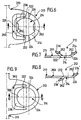
- the sealing plate projection is 212 not just with a screw hole 214 provided, but according to the invention also with a punched out window 260 which is between the screw hole 214 and the root of the sealing plate projection 212 and about a half of the screw hole surrounds in an arc, so that two from the plane of the sheet metal layer 210 bendable, arcuate sheet metal layer areas 234 and 236 with the central axis 226 of the plate projection 212 in particular mirror-symmetrical shape arise.
- the sheet layer 210 is now bent, thereby the sheet metal layer areas 234 and 236 from the plane of FIG Sheet layer 210 bent out, either on the same Side (see Fig. 7) or on opposite sides Pages (see FIG. 8) of the sheet layer 210 - in FIG. 8 were the bent sheet metal layer areas with 234 'and 236' designated.
- Figures 9 to 11 show the figures 6 to 8 quite similar Embodiments, but without the retaining projections Embodiment according to Figures 6 to 8, so that a description of Figures 9 to 11 can be dispensed with after in these the same reference numerals as in Figures 6 to 8 were drawn in, but with the number 3 (instead of the number 2) as the first digit.
- FIG. 12 shows a modification of the embodiment according to FIGS. 9 and 10, which is why in FIG. 12 the same reference numerals as used in Figures 9 and 10 but with the addition of two lines.
- the embodiment 12 differs from that of Figures 9 and 10 only in that from the level of Sheet metal layer 310 '' bent sheet metal layer areas 334 '' and 336 '' have been turned in again so their related the center of the screw hole radially outer edge areas run approximately parallel to the plane of the sheet metal layer 310 ′′.
- This also shortens again the diameter coinciding with the central axis 426 of the screw hole 414 (in the plan view of the Sheet layer 410 seen).
Landscapes
- Engineering & Computer Science (AREA)
- General Engineering & Computer Science (AREA)
- Mechanical Engineering (AREA)
- Gasket Seals (AREA)
Applications Claiming Priority (2)
| Application Number | Priority Date | Filing Date | Title |
|---|---|---|---|
| DE19932727 | 1999-07-14 | ||
| DE1999132727 DE19932727C1 (de) | 1999-07-14 | 1999-07-14 | Dichtung, insbesondere für Kraftfahrzeuge |
Publications (1)
| Publication Number | Publication Date |
|---|---|
| EP1069351A2 true EP1069351A2 (fr) | 2001-01-17 |
Family
ID=7914627
Family Applications (1)
| Application Number | Title | Priority Date | Filing Date |
|---|---|---|---|
| EP20000112560 Withdrawn EP1069351A2 (fr) | 1999-07-14 | 2000-06-14 | Joint d'étanchéité en particulier pour véhicule automobile |
Country Status (2)
| Country | Link |
|---|---|
| EP (1) | EP1069351A2 (fr) |
| DE (1) | DE19932727C1 (fr) |
Families Citing this family (2)
| Publication number | Priority date | Publication date | Assignee | Title |
|---|---|---|---|---|
| DE10313732A1 (de) * | 2003-03-27 | 2004-10-21 | Federal-Mogul Sealing Systems Bretten Gmbh & Co. Kg | Formstabile Elastomerdichtung |
| DE10314693B4 (de) * | 2003-03-28 | 2005-06-16 | Elringklinger Ag | Flachdichtung |
Citations (1)
| Publication number | Priority date | Publication date | Assignee | Title |
|---|---|---|---|---|
| DE29809130U1 (de) | 1998-05-20 | 1998-09-03 | Elring Klinger GmbH, 72581 Dettingen | Dichtung, insbesondere für Kraftfahrzeuge |
-
1999
- 1999-07-14 DE DE1999132727 patent/DE19932727C1/de not_active Expired - Fee Related
-
2000
- 2000-06-14 EP EP20000112560 patent/EP1069351A2/fr not_active Withdrawn
Patent Citations (1)
| Publication number | Priority date | Publication date | Assignee | Title |
|---|---|---|---|---|
| DE29809130U1 (de) | 1998-05-20 | 1998-09-03 | Elring Klinger GmbH, 72581 Dettingen | Dichtung, insbesondere für Kraftfahrzeuge |
Also Published As
| Publication number | Publication date |
|---|---|
| DE19932727C1 (de) | 2000-11-30 |
Similar Documents
| Publication | Publication Date | Title |
|---|---|---|
| EP1979634B1 (fr) | Unité de montage destinée à un anneau de fixation d'une boucle de ceinture | |
| EP3649353B1 (fr) | Système de fixation | |
| DE19504186C2 (de) | Axialdichtung | |
| WO2003093683A2 (fr) | Ecrou et son procede de production | |
| DE202006007821U1 (de) | Spann- oder Führungsschiene mit Verliersicherung für Haltebolzen | |
| WO2018010738A1 (fr) | Dispositif de fixation sur une pièce | |
| EP1469208B1 (fr) | Elément de vissage avec un élément intègralement formé de ressort | |
| EP1134463A2 (fr) | Dispositif de fixation d'un joint plat sur un élément de machine | |
| EP0959273B1 (fr) | Joint d'étanchéité, en particulier pour véhicule automobile | |
| EP1772633B1 (fr) | Liaison par vissage de deux éléments avec compensation de tolérance | |
| DE19932727C1 (de) | Dichtung, insbesondere für Kraftfahrzeuge | |
| DE10020218B4 (de) | Montageeinheit aus einem Bauteil und mindestens einer gewindeformenden Schraube | |
| DE1813758A1 (de) | Selbsthemmende Schraubenmutter | |
| DE19860085B4 (de) | Selbstschneidendes metallisches Gewindeteil | |
| DE4313845C1 (de) | Sicherungsmutter | |
| DE102015122766A1 (de) | "Zahnscheibe mit mehrstegigen Haltezähnen" | |
| EP3926184B1 (fr) | Élément rivet aveugle, en particulier pour la fabrication d'un raccordement à vis dans un composant | |
| CH553903A (de) | Vorrichtung zum arretieren eines eine oeffnung verschliessenden elementes. | |
| DE102017223636A1 (de) | Montageeinheit sowie Fixierhülse für eine solche Montageeinheit | |
| DE10135335B4 (de) | Flachdichtung | |
| DE102020109386A1 (de) | Verdrehsicherung für eine Schraube oder eine Schraubenmutter | |
| DE102019219288A1 (de) | Schnellmontageverbinder, Anordnung und Verfahren zum Fixieren eines Schnellmontageverbinders | |
| DE20105250U1 (de) | Flachdichtung | |
| EP4256210B1 (fr) | Rondelle de recouvrement de fentes | |
| DE102009038080A1 (de) | Verbindungsanordnung sowie Verfahren zum Herstellen einer Verbindungsanordnung |
Legal Events
| Date | Code | Title | Description |
|---|---|---|---|
| PUAI | Public reference made under article 153(3) epc to a published international application that has entered the european phase |
Free format text: ORIGINAL CODE: 0009012 |
|
| AK | Designated contracting states |
Kind code of ref document: A2 Designated state(s): AT BE CH CY DE DK ES FI FR GB GR IE IT LI LU MC NL PT SE |
|
| AX | Request for extension of the european patent |
Free format text: AL;LT;LV;MK;RO;SI |
|
| RAP1 | Party data changed (applicant data changed or rights of an application transferred) |
Owner name: ELRINGKLINGER AG |
|
| STAA | Information on the status of an ep patent application or granted ep patent |
Free format text: STATUS: THE APPLICATION HAS BEEN WITHDRAWN |
|
| 18W | Application withdrawn |
Withdrawal date: 20020118 |