EP1069351A2 - Gasket in partucular for motor vehicle - Google Patents
Gasket in partucular for motor vehicle Download PDFInfo
- Publication number
- EP1069351A2 EP1069351A2 EP20000112560 EP00112560A EP1069351A2 EP 1069351 A2 EP1069351 A2 EP 1069351A2 EP 20000112560 EP20000112560 EP 20000112560 EP 00112560 A EP00112560 A EP 00112560A EP 1069351 A2 EP1069351 A2 EP 1069351A2
- Authority
- EP
- European Patent Office
- Prior art keywords
- metal layer
- sheet metal
- screw
- screw hole
- flat gasket
- Prior art date
- Legal status (The legal status is an assumption and is not a legal conclusion. Google has not performed a legal analysis and makes no representation as to the accuracy of the status listed.)
- Withdrawn
Links
- 239000002184 metal Substances 0.000 claims abstract description 86
- 238000007789 sealing Methods 0.000 claims abstract description 32
- 230000000149 penetrating effect Effects 0.000 claims abstract description 4
- 210000002105 tongue Anatomy 0.000 claims description 15
- 238000004049 embossing Methods 0.000 claims description 5
- 239000010410 layer Substances 0.000 description 75
- 230000006378 damage Effects 0.000 description 6
- 238000005452 bending Methods 0.000 description 5
- 229910000639 Spring steel Inorganic materials 0.000 description 1
- 208000027418 Wounds and injury Diseases 0.000 description 1
- 230000000712 assembly Effects 0.000 description 1
- 238000000429 assembly Methods 0.000 description 1
- 238000002485 combustion reaction Methods 0.000 description 1
- 238000010276 construction Methods 0.000 description 1
- 230000007717 exclusion Effects 0.000 description 1
- 208000014674 injury Diseases 0.000 description 1
- 230000004048 modification Effects 0.000 description 1
- 238000012986 modification Methods 0.000 description 1
- 239000012858 resilient material Substances 0.000 description 1
- 210000005181 root of the tongue Anatomy 0.000 description 1
- 238000004904 shortening Methods 0.000 description 1
- 239000002356 single layer Substances 0.000 description 1
- 239000012207 thread-locking agent Substances 0.000 description 1
Images


Classifications
-
- F—MECHANICAL ENGINEERING; LIGHTING; HEATING; WEAPONS; BLASTING
- F16—ENGINEERING ELEMENTS AND UNITS; GENERAL MEASURES FOR PRODUCING AND MAINTAINING EFFECTIVE FUNCTIONING OF MACHINES OR INSTALLATIONS; THERMAL INSULATION IN GENERAL
- F16B—DEVICES FOR FASTENING OR SECURING CONSTRUCTIONAL ELEMENTS OR MACHINE PARTS TOGETHER, e.g. NAILS, BOLTS, CIRCLIPS, CLAMPS, CLIPS OR WEDGES; JOINTS OR JOINTING
- F16B41/00—Measures against loss of bolts, nuts, or pins; Measures against unauthorised operation of bolts, nuts or pins
- F16B41/002—Measures against loss of bolts, nuts or pins
-
- F—MECHANICAL ENGINEERING; LIGHTING; HEATING; WEAPONS; BLASTING
- F16—ENGINEERING ELEMENTS AND UNITS; GENERAL MEASURES FOR PRODUCING AND MAINTAINING EFFECTIVE FUNCTIONING OF MACHINES OR INSTALLATIONS; THERMAL INSULATION IN GENERAL
- F16J—PISTONS; CYLINDERS; SEALINGS
- F16J15/00—Sealings
- F16J15/02—Sealings between relatively-stationary surfaces
- F16J15/06—Sealings between relatively-stationary surfaces with solid packing compressed between sealing surfaces
- F16J15/061—Sealings between relatively-stationary surfaces with solid packing compressed between sealing surfaces with positioning means
-
- F—MECHANICAL ENGINEERING; LIGHTING; HEATING; WEAPONS; BLASTING
- F16—ENGINEERING ELEMENTS AND UNITS; GENERAL MEASURES FOR PRODUCING AND MAINTAINING EFFECTIVE FUNCTIONING OF MACHINES OR INSTALLATIONS; THERMAL INSULATION IN GENERAL
- F16J—PISTONS; CYLINDERS; SEALINGS
- F16J15/00—Sealings
- F16J15/02—Sealings between relatively-stationary surfaces
- F16J15/06—Sealings between relatively-stationary surfaces with solid packing compressed between sealing surfaces
- F16J15/08—Sealings between relatively-stationary surfaces with solid packing compressed between sealing surfaces with exclusively metal packing
- F16J15/0818—Flat gaskets
-
- F—MECHANICAL ENGINEERING; LIGHTING; HEATING; WEAPONS; BLASTING
- F16—ENGINEERING ELEMENTS AND UNITS; GENERAL MEASURES FOR PRODUCING AND MAINTAINING EFFECTIVE FUNCTIONING OF MACHINES OR INSTALLATIONS; THERMAL INSULATION IN GENERAL
- F16J—PISTONS; CYLINDERS; SEALINGS
- F16J15/00—Sealings
- F16J15/02—Sealings between relatively-stationary surfaces
- F16J15/06—Sealings between relatively-stationary surfaces with solid packing compressed between sealing surfaces
- F16J15/08—Sealings between relatively-stationary surfaces with solid packing compressed between sealing surfaces with exclusively metal packing
- F16J15/0818—Flat gaskets
- F16J2015/085—Flat gaskets without fold over
Definitions
- the sheet layer is made of a resilient material, like spring steel sheet, it is basically possible to get one Insert the screw in the screw hole in question without having to turn them; because with this known construction the length of the retaining tabs measured in the radial direction however, is relatively small and less than one Corresponds to a quarter of the core diameter of the screw thread, it may be advisable that Screw when inserting into the screw hole damage to the screw thread by the retaining tongues to rule out with certainty. However, even then still the risk of damage to the screw thread, and when tightening the mounting screws, d. H.
- the invention was based on the object of this known seal so improve that the threadlocker never damage the screw thread can lead and open up the basic possibility the screw crossing the screw hole at least approximately to keep perpendicular to the plane of the sealing plate.
- the basic idea of the present invention is therefore that To choose the shape and the course of the screw hole edge that on the one hand, as long as said sheet metal layer area from the The sheet metal layer is bent out, the screw hole - in a top view of the sheet metal layer - at least one diagonal has which is smaller than the outer diameter of the Screw thread is so that opposite to each other Engage hole edge sections in the screw thread, and that, on the other hand, the screw hole with flat pressed sheet metal in the top view of the sheet layer in each hole diagonal is so large that the screw hole edge everywhere Screw shaft releases.
- the screw can be under Exclusion of a risk of damage in the screw hole insert it without having to turn it; on the other hand is then not guaranteed without additional measures, that the screw is at least approximately perpendicular to Level of the sheet metal layer is held.
- the latter can be done with Achieve embodiments of the seal according to the invention, in which from the level of the sheet metal layer at least two Sheet layer areas are bent out, each one Hole edge section forms.
- the seal of the invention in which also no risk of injury when handling the seal consists in that the screw hole in one Sealing plate projection is located, which is adjacent to it Outer contour areas of the sealing plate protrudes, and that the sheet metal layer with a top view of the latter is approximately rectilinear embossed, which turns to both sides of the screw hole roughly transverse to that Extends in the direction in which the sealing plate projection protrudes the adjacent outer contour areas of the sealing plate.
- the screw hole is in Direction of the diagonals perpendicular to the embossing shortened, and by pressing the sheet metal layer flat this is Shortened again.
- the screw hole in a sealing plate protrusion lies, the outer contour areas of the sealing plate adjacent to it projecting, it may be advisable to take the lead by a from the outer edge of the sheet to To split the screw hole extending slot into two sheet metal tongues, the one from the level of the sheet metal layer form the bent sheet metal layer area.
- the screw can be approx Hold perpendicular to the sheet layer, depending on the Sheet thickness and the elastic properties of the sheet layer you can also just let the screw into the To insert the screw hole (without turning it) without the screw thread would be damaged.
- Fig. 1 shows part of a sheet metal layer 10, which the Form sealing plate of a flat gasket; in one of the sheet metal layer 10 formed sealing plate projection 12 is located a screw hole 14, the hole edge 16 then, if the entire sealing plate projection 12 in the plane the sheet metal layer 10 (drawing plane of FIG. 1), as this should be the case in Fig. 1, the shape of a circle has a diameter of the same size or very slight is larger than the outside diameter of the thread in the Screw hole 14 to be introduced, not shown Screw. As can be seen in FIG. 1, the sealing plate projection protrudes 12 outer contour areas adjacent to it 18 and 20 of the sealing plate formed by the sheet metal layer 10 out.
- Fig. 1 are two straight bend lines 22 and 24 drawn in, which is a mirror image of a central axis 26 of the sealing plate projection 12 run - the central axis 26 runs through the center 30 of the initially circular Screw hole 14.
- the invention is now at least in the area of its projection 12 first a flat sheet metal layer 10 along the fold lines 22 and 24 from the plane of Sheet metal layer 10 (drawing plane of FIG. 1) bent out, so that two bent out of the sheet layer level Sheet layer areas 34 and 36 result.
- Such a turn is due to the course of the fold lines 22 and 24 as well the outer contour of the sealing plate projection 12 easily possible.
- the two sheet metal layer areas bent out of the plane of the sheet metal layer either in opposite directions or in the same direction Be bent out of the plane of the sheet metal layer; in any case, the bending out of the two sheet metal layers leads seen in the top view of the sheet metal layer 10, too a reduction in the diameter of the screw hole 14 in Direction of the diagonal 40 shown in FIG Screw hole, with the bevel angle chosen only as large may be that of the two sheet metal layers 34 and 36 formed hole edge portions 34a and 36a in engage the screw thread, but preferably not rest against the core of the screw thread.
- the embodiment according to FIGS. 1 and 2 can be designed in this way that the screw is in the screw hole 14 can be inserted (without rotation) if the axis of the threaded shaft the screw obliquely to that shown in FIG. 2 Hole axis runs.
- FIGS. 4 to 14 will only be described in the following as this is necessary for their understanding; be there where possible the same reference numerals as in Fig. 1 are used , but with numbers 1 and 2 in front or 3 etc.
- a Shortening the initially circular screw hole 114 achieved that the sealing plate projection 112 with an embossment 122 indicated by dash-dotted lines in FIG. 4, which is transverse to the central axis 126 of the sealing plate projection extends over its entire width and how 5, an approximately sinusoidal cross section having.
- the hole edge designated as a whole by 116 the screw again when the sealing plate projection 112 is flattened becomes.
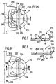
- the sealing plate projection is 212 not just with a screw hole 214 provided, but according to the invention also with a punched out window 260 which is between the screw hole 214 and the root of the sealing plate projection 212 and about a half of the screw hole surrounds in an arc, so that two from the plane of the sheet metal layer 210 bendable, arcuate sheet metal layer areas 234 and 236 with the central axis 226 of the plate projection 212 in particular mirror-symmetrical shape arise.
- the sheet layer 210 is now bent, thereby the sheet metal layer areas 234 and 236 from the plane of FIG Sheet layer 210 bent out, either on the same Side (see Fig. 7) or on opposite sides Pages (see FIG. 8) of the sheet layer 210 - in FIG. 8 were the bent sheet metal layer areas with 234 'and 236' designated.
- Figures 9 to 11 show the figures 6 to 8 quite similar Embodiments, but without the retaining projections Embodiment according to Figures 6 to 8, so that a description of Figures 9 to 11 can be dispensed with after in these the same reference numerals as in Figures 6 to 8 were drawn in, but with the number 3 (instead of the number 2) as the first digit.
- FIG. 12 shows a modification of the embodiment according to FIGS. 9 and 10, which is why in FIG. 12 the same reference numerals as used in Figures 9 and 10 but with the addition of two lines.
- the embodiment 12 differs from that of Figures 9 and 10 only in that from the level of Sheet metal layer 310 '' bent sheet metal layer areas 334 '' and 336 '' have been turned in again so their related the center of the screw hole radially outer edge areas run approximately parallel to the plane of the sheet metal layer 310 ′′.
- This also shortens again the diameter coinciding with the central axis 426 of the screw hole 414 (in the plan view of the Sheet layer 410 seen).
Landscapes
- Engineering & Computer Science (AREA)
- General Engineering & Computer Science (AREA)
- Mechanical Engineering (AREA)
- Gasket Seals (AREA)
Abstract
Flachdichtung mit einer Dichtungsplatte, welche mindestens eine Blechlage aufweist, die mit einem Schraubenloch für den Durchtritt des Gewindeschafts einer Schraube und mit einer Verliersicherung für die Schraube versehen ist; damit beim Einbau der Flachdichtung das Schraubengewinde durch die Verliersicherung nicht beschädigt werden kann, weist letztere die folgenden Merkmale auf: (a) mindestens ein einen Abschnitt des Schraubenlochrands bildender Blechlagenbereich ist derart aus der Ebene der Blechlage herausgebogen, daß - senkrecht zur Ebene der Blechlage gesehen - mindestens ein Lochrandabschnitt von einem diesem gegenüberliegenden Lochrandabschnitt einen Abstand aufweist, welcher kleiner als der Außendurchmesser des Schraubenschafts, jedoch mindestens gleich dem Kerndurchmesser des Schraubengewindes ist; (b) der Schraubenlochrand ist so gestaltet, daß er bei im Bereich des Schraubenlochs flachgepreßter Blechlage den das Schraubenloch durchgreifenden Gewindeschaft freigibt. <IMAGE>Flat gasket with a sealing plate, which has at least one sheet metal layer, which is provided with a screw hole for the passage of the threaded shaft of a screw and with an anti-loss device for the screw; So that the screw thread cannot be damaged by the captive lock when installing the flat seal, the latter has the following features: (a) at least one sheet layer area forming a section of the screw hole edge is bent out of the plane of the sheet layer in such a way that - seen perpendicular to the plane of the sheet layer - At least one hole edge section is at a distance from a hole edge section opposite this, which distance is smaller than the outer diameter of the screw shaft, but at least equal to the core diameter of the screw thread; (b) the edge of the screw hole is designed such that it releases the threaded shaft penetrating the screw hole when the sheet metal layer is pressed flat in the area of the screw hole. <IMAGE>
Description
Die Erfindung betrifft eine Flachdichtung, insbesondere eine Dichtung für eine Kraftfahrzeugkomponente, wie einen Ansaugkrümmer, wobei die Dichtungsplatte der Flachdichtung mindestens eine Blechlage aufweist, die mit wenigstens einem Schraubenloch für den Durchtritt des Gewindeschafts einer Schraube versehen ist, welche der Befestigung der Fahrzeugkomponente und dem Anziehen der Dichtung dient, also z. B. der Befestigung des Ansaugkrümmers und der Dichtung am Zylinderkopf eines Verbrennungsmotors.The invention relates to a flat gasket, in particular a Gasket for an automotive component, such as an intake manifold, the sealing plate of the flat gasket at least has a sheet metal layer which with at least one Screw hole for the passage of the threaded shaft Screw is provided, which is the fastening of the vehicle component and is used to tighten the seal, e.g. B. the attachment of the intake manifold and the seal on Cylinder head of an internal combustion engine.
Fahrzeughersteller verlangen in immer größerem Umfang von ihren Zulieferern, daß letztere Bauteile samt zugehörigen Komponenten in vormontiertem Zustand anliefern. Aber selbst wenn ein Zulieferer ein Bauteil ohne zugehörige Komponenten liefert, werden die letzteren im Werk des Fahrzeugherstellers oft schon am Bauteil angebracht, ehe dieses zur Montage an das Montageband gebracht wird. Deshalb wird im Zuge der vorstehend beschriebenen Bestrebungen gefordert, daß die Dichtung samt Montageschrauben an das Montageband angeliefert wird, wobei die Schrauben verliersicher an der Dichtung gehalten werden sollen. Angestrebt wird sogar, daß ganze vormontierte Baugruppen an das Montageband angeliefert werden, also z. B. eine Baugruppe bestehend aus einem Ansaugkrümmer, der zugehörigen Flachdichtung und den zugehörigen Montageschrauben, wobei die Dichtung über eine oder mehrere Schrauben auf dem Ansaugkrümmer unverlierbar vormontiert ist. Eine solche vormontierte Baugruppe kann nun mit einer Hand am Motor angesetzt werden, während sich mit der anderen Hand die Montageschrauben anziehen lassen. Vehicle manufacturers are demanding more and more their suppliers that the latter components including associated Deliver components in pre-assembled condition. But yourself if a supplier has a component without associated components supplies, the latter are in the vehicle manufacturer's factory often already attached to the component before it is installed the assembly line is brought. Therefore, in the course of the above aspirations described that the seal delivered with assembly screws to the assembly line the screws are held captive on the seal should be. It is even sought that whole pre-assembled Assemblies are delivered to the assembly line, so z. B. an assembly consisting of an intake manifold, the associated flat gasket and the associated mounting screws, the seal over one or more screws is captively pre-assembled on the intake manifold. A such a pre-assembled assembly can now be carried out with one hand Engine are attached while the other hand Have the mounting screws tightened.
Das DE-U-298 09 130.5 der Firma Elring Klinger GmbH zeigt eine Flachdichtung mit einer einzigen Blechlage und mehreren Schraubenlöchern, von denen einige mit Mitteln versehen sind, um Schrauben verliersicher an der Dichtung zu halten. Bei diesen Sicherungsmitteln handelt es sich um mehrere, vom Rand des Schraubenlochs in Richtung zum Zentrum des dem Grunde nach kreisrunden Lochs abstehende Haltezungen, welche über den Lochumfang gleichmäßig verteilt und im Abstand voneinander angeordnet sind; während eine der Haltezungen in der Ebene der Blechlage liegt, sind die anderen durch Abbiegen des Blechs an der Zungenwurzel sowie im Abstand vom vorderen Zungenende derart aus der Ebene der Blechlage herausgebogen, daß die dem Lochzentrum zugewandten Randbereiche der Haltezungen der Steigung des Schraubengewindes entsprechend in Achsrichtung des Schraubenlochs gegeneinander versetzt angeordnet sind, wobei - in der Draufsicht auf die Blechlage - die dem Lochzentrum zugewandten Randbereiche der Haltezungen ein kreisförmiges Kernloch definieren, dessen Durchmesser dem Kerndurchmesser des Schraubengewindes entspricht, so daß diese Randbereiche in das Schraubengewinde eingreifen können. Besteht die Blechlage aus einem federnd nachgiebigen Material, wie Federstahlblech, ist es grundsätzlich möglich, eine Schraube in das betreffende Schraubenloch einzustecken, ohne sie drehen zu müssen; da bei dieser bekannten Konstruktion die in radialer Richtung gemessene Länge der Haltezungen jedoch verhältnismäßig gering ist und weniger als einem Viertel des Kerndurchmessers des Schraubengewindes entspricht, kann es unter Umständen empfehlenswert sein, die Schraube beim Einbringen in das Schraubenloch zu drehen, um eine Beschädigung des Schraubengewindes durch die Haltezungen mit Sicherheit auszuschließen. Allerdings besteht selbst dann noch das Risiko einer Beschädigung des Schraubengewindes, und zwar beim Anziehen der Montageschrauben, d. h. beim Einspannen der Dichtung zwischen den durch die Dichtung gegeneinander abzudichtenden Bauteilen, da ein Teil der Haltezungen unterschiedlich weit aus der Ebene der Blechlage herausgebogen ist, die dem Zentrum des Schraubenlochs zugewandten Randbereiche der Haltezungen jedoch ein kreisförmiges Kernloch definieren, dessen Durchmesser dem Kerndurchmesser des Schraubengewindes entspricht, so daß die radial inneren Enden der Haltezungen beim Einspannen der Dichtung die Tendenz haben, ein Loch mit einem Durchmesser zu bilden, welcher kleiner als der Kerndurchmesser des Schraubengewindes ist, was zu Verwerfungen der Haltezungen und/oder zu Beschädigungen des Schraubengewindes durch die Haltezungen führen kann.DE-U-298 09 130.5 from Elring Klinger GmbH shows a flat gasket with a single sheet layer and several Screw holes, some of which are provided with means, to keep screws captive on the seal. At These means of protection are several, from the edge of the screw hole towards the center of the bottom after circular holes protruding tabs, which over the circumference of the hole is evenly spaced and spaced apart are arranged; while one of the retaining tongues in the Level of the sheet metal layer, the others are by turning of the sheet at the root of the tongue and at a distance from the front Tongue end bent out of the plane of the sheet metal layer in such a way that the edge areas of the retaining tongues facing the hole center corresponding to the pitch of the screw thread Axial direction of the screw hole offset from each other are, where - in the plan view of the sheet metal layer - the edge areas of the holding tongues facing the hole center define a circular core hole, the diameter of which Core diameter of the screw thread corresponds so that these edge areas can engage in the screw thread. If the sheet layer is made of a resilient material, like spring steel sheet, it is basically possible to get one Insert the screw in the screw hole in question without having to turn them; because with this known construction the length of the retaining tabs measured in the radial direction however, is relatively small and less than one Corresponds to a quarter of the core diameter of the screw thread, it may be advisable that Screw when inserting into the screw hole damage to the screw thread by the retaining tongues to rule out with certainty. However, even then still the risk of damage to the screw thread, and when tightening the mounting screws, d. H. when clamping the seal between those against each other by the seal components to be sealed, as part of the retaining tongues bent out of the plane of the sheet metal layer to different degrees is facing the center of the screw hole Edge areas of the retaining tongues, however, a circular core hole define the diameter of which corresponds to the core diameter of the Screw thread corresponds, so that the radially inner ends the holding tongues the tendency when clamping the seal have to form a hole with a diameter which is smaller than the core diameter of the screw thread, causing warping of the retaining tongues and / or damage of the screw thread through the retaining tongues can.
Der Erfindung lag die Aufgabe zugrunde, diese bekannte Dichtung so zu verbessern, daß die Schraubensicherungsmittel keinesfalls zu einer Beschädigung des Schraubengewindes führen können und die grundsätzliche Möglichkeit eröffnen, die das Schraubenloch durchquerende Schraube zumindest ungefähr senkrecht zur Ebene der Dichtungsplatte zu halten.The invention was based on the object of this known seal so improve that the threadlocker never damage the screw thread can lead and open up the basic possibility the screw crossing the screw hole at least approximately to keep perpendicular to the plane of the sealing plate.
Ausgehend von einer Flachdichtung mit einer Dichtungsplatte,
welche mindestens eine Blechlage aufweist, die mit wenigstens
einem Schraubenloch für den Durchtritt des Gewindeschafts
einer Schraube sowie im Randbereich des Schraubenlochs mit
von der Blechlage gebildeten, aus der Ebene der Blechlage
herausgebogenen Schraubenhaltemitteln versehen ist, läßt sich
diese Aufgabe erfindungsgemäß durch die Kombination der folgenden
Merkmale lösen:
Grundgedanke der vorliegenden Erfindung ist es also, die Gestalt und den Verlauf des Schraubenlochrands so zu wählen, daß einerseits, solange der besagte Blechlagenbereich aus der Ebene der Blechlage herausgebogen ist, das Schraubenloch - in einer Draufsicht auf die Blechlage - mindestens eine Diagonale besitzt, welche kleiner als der Außendurchmesser des Schraubengewindes ist, so daß einander gegenüberliegende Lochrandabschnitte in das Schraubengewinde eingreifen, und daß andererseits bei flachgepreßter Blechlage das Schraubenloch in der Draufsicht auf die Blechlage in jeder Lochdiagonale so groß ist, daß der Schraubenlochrand überall den Schraubenschaft freigibt.The basic idea of the present invention is therefore that To choose the shape and the course of the screw hole edge that on the one hand, as long as said sheet metal layer area from the The sheet metal layer is bent out, the screw hole - in a top view of the sheet metal layer - at least one diagonal has which is smaller than the outer diameter of the Screw thread is so that opposite to each other Engage hole edge sections in the screw thread, and that, on the other hand, the screw hole with flat pressed sheet metal in the top view of the sheet layer in each hole diagonal is so large that the screw hole edge everywhere Screw shaft releases.
Insbesondere dann, wenn nur ein einziger, einen Lochrandabschnitt bildender Blechlagenbereich aus der Ebene der Blechlage herausgebogen ist, läßt sich die Schraube unter Ausschluß eines Beschädigungsrisikos in das Schraubenloch einstecken, ohne daß sie dabei gedreht werden muß; andererseits ist dann ohne zusätzliche Maßnahmen nicht gewährleistet, daß die Schraube mindestens ungefähr senkrecht zur Ebene der Blechlage gehalten wird. Letzteres läßt sich mit Ausführungsformen der erfindungsgemäßen Dichtung erreichen, bei denen aus der Ebene der Blechlage mindestens zwei Blechlagenbereiche herausgebogen sind, deren jeder einen Lochrandabschnitt bildet.In particular, if only one, a hole edge section forming sheet metal layer area from the level of Sheet is bent out, the screw can be under Exclusion of a risk of damage in the screw hole insert it without having to turn it; on the other hand is then not guaranteed without additional measures, that the screw is at least approximately perpendicular to Level of the sheet metal layer is held. The latter can be done with Achieve embodiments of the seal according to the invention, in which from the level of the sheet metal layer at least two Sheet layer areas are bent out, each one Hole edge section forms.
Da es, wie vorstehend dargelegt wurde, für die Verwirklichung des Grundprinzips der Erfindung nur darauf ankommt, daß das Schraubenloch durch Verbiegen der Blechlage z. B. in Richtung einer Diagonalen verkürzt wird - in der Draufsicht auf die Blechlage gesehen -, zeichnen sich besonders einfache Ausführungsformen der erfindungsgemäßen Dichtung, bei denen auch nicht die Gefahr einer Verletzung beim Handhaben der Dichtung besteht, dadurch aus, daß sich das Schraubenloch in einem Dichtungsplattenvorsprung befindet, welcher über ihm benachbarte Außenkonturbereiche der Dichtungsplatte vorsteht, und daß die Blechlage mit einer in der Draufsicht auf letztere ungefähr geradlinigen Prägung versehen ist, welche sich zu beiden Seiten des Schraubenlochs ungefähr quer zu derjenigen Richtung erstreckt, in der der Dichtungsplattenvorsprung über die benachbarten Außenkonturbereiche der Dichtungsplatte vorsteht. Durch eine solche Prägung wird das Schraubenloch in Richtung der senkrecht zur Prägung verlaufenden Diagonalen verkürzt, und durch Flachpressen der Blechlage wird diese Verkürzung wieder aufgehoben.Since, as stated above, for realization the basic principle of the invention depends only on the fact that Screw hole by bending the sheet layer z. B. towards a diagonal is shortened - in the top view of the Seen sheet metal layer -, stand out particularly simple embodiments the seal of the invention, in which also no risk of injury when handling the seal consists in that the screw hole in one Sealing plate projection is located, which is adjacent to it Outer contour areas of the sealing plate protrudes, and that the sheet metal layer with a top view of the latter is approximately rectilinear embossed, which turns to both sides of the screw hole roughly transverse to that Extends in the direction in which the sealing plate projection protrudes the adjacent outer contour areas of the sealing plate. With such an embossing, the screw hole is in Direction of the diagonals perpendicular to the embossing shortened, and by pressing the sheet metal layer flat this is Shortened again.
Wenn das Schraubenloch in einem Dichtungsplattenvorsprung liegt, der über ihm benachbarte Außenkonturbereiche der Dichtungsplatte vorsteht, kann es sich empfehlen, den Vorsprung durch einen sich vom äußeren Rand der Blechlage bis zum Schraubenloch erstreckenden Schlitz in zwei Blechzungen aufzuteilen, die jeweils einen aus der Ebene der Blechlage herausgebogenen Blechlagenbereich bilden. Durch solche herausgebogenen Blechzungen läßt sich die Schraube ungefähr senkrecht zur Blechlagenebene halten, in Abhängigkeit von der Blechstärke und den elastischen Eigenschaften der Blechlage können sie es aber auch zulassen, die Schraube einfach in das Schraubenloch einzustecken (ohne sie zu drehen), ohne daß dabei das Schraubengewinde beschädigt würde.If the screw hole in a sealing plate protrusion lies, the outer contour areas of the sealing plate adjacent to it projecting, it may be advisable to take the lead by a from the outer edge of the sheet to To split the screw hole extending slot into two sheet metal tongues, the one from the level of the sheet metal layer form the bent sheet metal layer area. Through such bent out sheet metal tongues, the screw can be approx Hold perpendicular to the sheet layer, depending on the Sheet thickness and the elastic properties of the sheet layer you can also just let the screw into the To insert the screw hole (without turning it) without the screw thread would be damaged.
Weitere Merkmale der erfindungsgemäßen Flachdichtung ergeben sich aus den beigefügten Ansprüchen und/oder aus der beigefügten zeichnerischen Darstellung sowie der nachfolgenden Beschreibung mehrerer besonders bevorzugter Ausführungsformen der Dichtung; in der Zeichnung zeigen:
- Fig. 1
- eine Draufsicht auf einen Ausschnitt aus einer einlagigen Flachdichtung, in dem sich ein mit erfindungsgemäßen Schraubenhaltemitteln versehenes Schraubenloch befindet;
- Fig. 2
- einen Schnitt nach der Linie 2-2 in Fig. 1;
- Fig. 3
- eine der Fig. 2 entsprechende Schnittdarstellung einer Variante der in Fig. 2 dargestellten Ausführungsform;
- Fig. 4
- eine der Fig. 1 entsprechende Darstellung einer dritten Ausführungsform;
- Fig. 5
- einen Schnitt nach der Linie 5-5 in Fig. 4;
- Fig. 6
- eine der Fig. 1 entsprechende Darstellung einer vierten Ausführungsform;
- Fig. 7
- einen Schnitt nach der Linie 7-7 in Fig. 6;
- Fig. 8
- eine der Fig. 7 entsprechende Schnittdarstellung einer fünften Ausführungsform;
- Fig. 9
- eine der Fig. 1 entsprechende Darstellung einer sechsten Ausführungsform;
- Figuren 10 - 12
- Schnitte durch die sechste, eine siebte und eine achte Ausführungsform gemäß der Linie 10-10 in Fig. 9;
- Fig. 13
- eine der Fig. 1 entsprechende Darstellung einer neunten Ausführungsform und
- Fig. 14
- einen Schnitt nach der Linie 14-14 in Fig. 13.
- Fig. 1
- a plan view of a section of a single-layer flat gasket, in which there is a screw hole provided with screw holding means according to the invention;
- Fig. 2
- a section along the line 2-2 in Fig. 1;
- Fig. 3
- 2 shows a sectional illustration corresponding to a variant of the embodiment shown in FIG. 2;
- Fig. 4
- a representation corresponding to Figure 1 of a third embodiment.
- Fig. 5
- a section along the line 5-5 in Fig. 4;
- Fig. 6
- a representation of a fourth embodiment corresponding to FIG. 1;
- Fig. 7
- a section along the line 7-7 in Fig. 6;
- Fig. 8
- 7 shows a sectional illustration corresponding to a fifth embodiment;
- Fig. 9
- an illustration corresponding to Figure 1 of a sixth embodiment.
- Figures 10-12
- Cuts through the sixth, a seventh and an eighth embodiment along the line 10-10 in Fig. 9;
- Fig. 13
- 1 corresponding representation of a ninth embodiment and
- Fig. 14
- a section along the line 14-14 in Fig. 13th
Die Fig. 1 zeigt einen Teil einer Blechlage 10, welche die
Dichtungsplatte einer Flachdichtung bilden soll; in einem von
der Blechlage 10 gebildeten Dichtungsplattenvorsprung 12 befindet
sich ein Schraubenloch 14, dessen Lochrand 16 dann,
wenn der gesamte Dichtungsplattenvorsprung 12 in der Ebene
der Blechlage 10 (Zeichnungsebene der Fig. 1) liegt, so wie
dies in Fig. 1 der Fall sein soll, die Gestalt eines Kreises
hat, dessen Durchmesser gleich groß oder ganz geringfügig
größer ist wie der Außendurchmesser des Gewindes der in das
Schraubenloch 14 einzubringenden, nicht dargestellten
Schraube. Wie die Fig. 1 erkennen läßt, ragt der Dichtungsplattenvorsprung
12 über ihm benachbarte Außenkonturbereiche
18 und 20 der von der Blechlage 10 gebildeten Dichtungsplatte
hinaus. Fig. 1 shows part of a
In die Fig. 1 sind zwei geradlinige Abkantungslinien 22 und
24 eingezeichnet, welche spiegelbildlich zu einer Mittelachse
26 des Dichtungsplattenvorsprungs 12 verlaufen - die Mittelachse
26 verläuft durch das Zentrum 30 des zunächst kreisrunden
Schraubenlochs 14. Erfindungsgemäß ist nun die zumindest
im Bereich ihres Vorsprungs 12 zunächst ebene Blechlage
10 längs der Abkantungslinien 22 und 24 aus der Ebene der
Blechlage 10 (Zeichnungsebene der Fig. 1) heraus abgebogen,
so daß sich zwei aus der Blechlagenebene herausgebogene
Blechlagenbereiche 34 und 36 ergeben. Ein solches Abbiegen
ist infolge des Verlaufs der Abkantungslinien 22 und 24 sowie
der Außenkontur des Dichtungsplattenvorsprungs 12 ohne weiteres
möglich. Wie die Figuren 2 und 3 zeigen, können die beiden
aus der Ebene der Blechlage herausgebogenen Blechlagenbereiche
entweder in entgegengesetzte Richtungen oder in derselben
Richtung aus der Blechlagenebene herausgebogen sein;
in jedem Fall führt das Herausbiegen der beiden Blechlagenbereiche,
in der Draufsicht auf die Blechlage 10 gesehen, zu
einer Verkürzung des Durchmessers des Schraubenlochs 14 in
Richtung der in die Fig. 1 eingezeichneten Diagonale 40 des
Schraubenlochs, wobei der Abkantungswinkel nur so groß gewählt
werden darf, daß die von den beiden Blechlagenbereichen
34 und 36 gebildeten Lochrandabschnitte 34a bzw. 36a zwar in
das Schraubengewinde eingreifen, vorzugsweise jedoch nicht
gegen den Kern des Schraubengewindes anliegen.In Fig. 1 are two
Die Ausführungsform gemäß den Figuren 1 und 2 kann so gestaltet
werden, daß sich die Schraube in das Schraubenloch 14
einstecken läßt (ohne Drehung), wenn dabei die Achse des Gewindeschafts
der Schraube schräg zu der in die Fig. 2 eingezeichneten
Lochachse verläuft. Dies ist bei der Ausführungsform
nach den Figuren 1 und 3 nur möglich, wenn beim Einstecken
des Schraubenschafts die Blechlagenbereiche 34 und 36
hinreichend federnd ausweichen können; andererseits hat diese
Ausführungsform den Vorteil, daß die das Schraubenloch 14
durchgreifende Schraube ungefähr senkrecht zur Ebene der
Blechlage 10 gehalten wird.The embodiment according to FIGS. 1 and 2 can be designed in this way
that the screw is in the
Bei beiden Ausführungsformen wird beim Anziehen der Dichtung,
d. h. beim Anziehen der ihrer Montage dienenden Schrauben,
der Dichtungsplattenvorsprung 12 zwischen den gegeneinander
abzudichtenden Bauteilen flachgepreßt, wobei der Lochrand 16
des Schraubenlochs 14 das Schraubengewinde wieder freigibt.In both embodiments, when tightening the seal,
d. H. when tightening the screws used for their assembly,
the sealing
Die übrigen Ausführungsformen gemäß den Figuren 4 bis 14
werden im folgenden nur noch insoweit beschrieben werden, als
dies für deren Verständnis erforderlich ist; dabei werden
soweit möglich dieselben Bezugszeichen wie in Fig. 1 verwendet
werden, jedoch unter Voranstellen der Ziffer 1 bzw. 2
bzw. 3 etc.The remaining embodiments according to FIGS. 4 to 14
will only be described in the following as
this is necessary for their understanding; be there
where possible the same reference numerals as in Fig. 1 are used
, but with
Bei der Ausführungsform nach den Figuren 4 und 5 wird eine
Verkürzung des zunächst kreisrunden Schraubenlochs 114 dadurch
erreicht, daß man den Dichtungsplattenvorsprung 112 mit
einer in Fig. 4 strichpunktiert angedeuteten Prägung 122 versieht,
welche sich quer zur Mittelachse 126 des Dichtungsplattenvorsprungs
über dessen ganze Breite erstreckt und, wie
in Fig. 5 dargestellt, einen ungefähr sinusförmigen Querschnitt
aufweist. Damit verkürzt sich in der Draufsicht auf
die Blechlage 110 der mit der Mittelachse 126 des Schraubenlochs
zusammenfallende Lochdurchmesser so weit, daß die einander
diagonal gegenüberliegenden Lochrandabschnitte 134a und
136a in das Schraubengewinde eingreifen. Andererseits gibt
der als Ganzes mit 116 bezeichnete Lochrand die Schraube
wieder frei, wenn der Dichtungsplattenvorsprung 112 flachgedrückt
wird.In the embodiment according to FIGS. 4 and 5, a
Shortening the initially
Bei der in Fig. 6 dargestellten Blechlage 210 ist der Dichtungsplattenvorsprung
212 nicht nur mit einem Schraubenloch
214 versehen, sondern erfindungsgemäß auch noch mit einem
ausgestanzten Fenster 260, welches zwischen dem Schraubenloch
214 und der Wurzel des Dichtungsplattenvorsprungs 212 angeordnet
ist und ungefähr die eine Hälfte des Schraubenlochs
bogenförmig umgibt, so daß zwei aus der Ebene der Blechlage
210 herausbiegbare, bogenförmige Blechlagenbereiche 234 und
236 mit zur Mittelachse 226 des Plattenvorsprungs 212 insbesondere
spiegelsymmetrischer Gestalt entstehen. Längs zweier
quer zur Mittelachse 226 verlaufender Abkantungslinien 222
und 224 wird nun die Blechlage 210 abgebogen, dabei werden
die Blechlagenbereiche 234 und 236 aus der Ebene der
Blechlage 210 herausgebogen, und zwar entweder auf dieselbe
Seite (siehe Fig. 7) oder auf einander entgegengesetzte
Seiten (siehe Fig. 8) der Blechlage 210 - in Fig. 8 wurden
die herausgebogenen Blechlagenbereiche mit 234' und 236'
bezeichnet. An jeden dieser Blechlagenbereiche ist ein Haltevorsprung
262 bzw. 262' angestanzt, der bei aus der Blechlagenebene
herausgebogenen Blechlagenbereichen 234, 236 bzw.
234', 236' in das Schraubengewinde eingreifen soll; dabei
wurden die Lagen der Haltevorsprünge bzw. die Winkel, um die
die Blechlagenbereiche aus der Ebene der Blechlage 210
herausgebogen wurden, so gewählt, daß für den Eingriff der
Haltevorsprünge in das Schraubengewinde der Steigung des
Gewindegangs bzw. der Gewindegänge Rechnung getragen wird (in
Fig. 7 liegen deshalb die beiden Haltevorsprünge 262 nicht
auf demselben Niveau). In the
Die Figuren 9 bis 11 zeigen den Figuren 6 bis 8 recht ähnliche Ausführungsformen, jedoch ohne die Haltevorsprünge der Ausführungsform nach den Figuren 6 bis 8, so daß auf eine Beschreibung der Figuren 9 bis 11 verzichtet werden kann, nachdem in diese dieselben Bezugszeichen wie in den Figuren 6 bis 8 eingezeichnet wurden, jedoch mit der Zahl 3 (statt der Zahl 2) als erster Ziffer.Figures 9 to 11 show the figures 6 to 8 quite similar Embodiments, but without the retaining projections Embodiment according to Figures 6 to 8, so that a description of Figures 9 to 11 can be dispensed with after in these the same reference numerals as in Figures 6 to 8 were drawn in, but with the number 3 (instead of the number 2) as the first digit.
Die Fig. 12 zeigt schließlich noch eine Abwandlung der Ausführungsform
nach den Figuren 9 und 10, weshalb in Fig. 12
dieselben Bezugszeichen wie in den Figuren 9 und 10 verwendet
wurden, jedoch unter Hinzufügung zweier Striche. Die Ausführungsform
nach Fig. 12 unterscheidet sich von derjenigen nach
den Figuren 9 und 10 nur dadurch, daß die aus der Ebene der
Blechlage 310'' herausgebogenen Blechlagenbereiche 334'' und
336'' in sich noch einmal abgebogen wurden, damit ihre bezüglich
des Zentrums des Schraubenlochs radial äußeren Randbereiche
ungefähr parallel zur Ebene der Blechlage 310'' verlaufen.Finally, FIG. 12 shows a modification of the embodiment
according to FIGS. 9 and 10, which is why in FIG. 12
the same reference numerals as used in Figures 9 and 10
but with the addition of two lines. The
Bei der letzten, in den Figuren 13 und 14 dargestellten Ausführungsform
ist der von der Blechlage 410 gebildete Dichtungsplattenvorsprung
412 durch einen Schlitz 470 geteilt,
dessen Längsmittelachse mit der Mittelachse 426 des Dichtungsplattenvorsprungs
412 zusammenfällt. Dadurch entstehen
zwei aus der Ebene der Blechlage 410 herausbiegbare Blechlagenbereiche
434 und 436, welche die Gestalt bogenförmiger
Zungen haben und durch Biegen des Blechs längs einer quer zur
Mittelachse 426 verlaufenden Abkantungslinie 422 aus der
Ebene der Blechlage 410 herausgebogen werden können, und zwar
entweder auf dieselbe Seite (nicht dargestellt), oder auf
einander entgegengesetzte Seiten der Blechlage 410, so wie
dies in Fig. 14 dargestellt ist. Auch hierdurch verkürzt sich
wieder der mit der Mittelachse 426 zusammenfallende Durchmesser
des Schraubenlochs 414 (in der Draufsicht auf die
Blechlage 410 gesehen).In the last embodiment shown in FIGS. 13 and 14
is the sealing plate projection formed by the
Aufgrund der vorstehenden Beschreibung der Gestaltung und Funktion der erfindungsgemäßen Dichtung wird verständlich, daß sich die zeichnerisch dargestellten Ausführungsformen in folgender Weise modifizieren lassen, ohne dadurch vom Grundprinzip der Erfindung abzugehen:Based on the above description of the design and Function of the seal according to the invention can be understood that the illustrated embodiments in can be modified as follows, without thereby changing the basic principle to go away from the invention:
Bei einer Ausführungsform ähnlich derjenigen gemäß den Figuren
13 und 14 könnten die beiden zungenförmigen Blechlagenbereiche
434 und 436 auch von zwei aufeinandergeschichteten
Blechlagen gebildet werden, deren eine den Blechlagenbereich
434 und deren andere den Blechlagenbereich 436 bildet und
jeweils nur einen einzigen derartigen zungenförmigen Blechlagenbereich
besitzt. Entsprechendes gilt für die aus der
Dichtungsplattenebene herausgebogenen Blechlagenbereiche der
anderen, zeichnerisch dargestellten Ausführungsformen.In an embodiment similar to that according to the figures
13 and 14 could the two tongue-shaped sheet
Ferner wird aufgrund der vorstehenden Erläuterungen verständlich, daß die erfindungsgemäße Dichtung einen Nachteil nicht aufweist, welcher bei der eingangs beschriebenen bekannten Dichtung nach dem DE-U-298 09 130.5 auftreten kann: Werden bei der Montage dieser bekannten Dichtung die Montageschrauben, wie üblich, mit einem vorgegebenen Drehmoment angezogen, bedeutet die Erreichung des Drehmomentgrenzwertes noch nicht, daß die mittels der Dichtung gegeneinander abzudichtenden Bauteile mit der gewünschten Flächenpressung gegen die Dichtung anliegen, da ein Anstieg des Anzugsdrehmoments auf Verwerfungen der in das Schraubengewinde eingreifenden Haltezungen der bekannten Dichtung beruhen kann.Furthermore, based on the above explanations, it is understandable that the seal of the invention does not have a disadvantage has, which in the known described above Seal according to DE-U-298 09 130.5 can occur: Will when mounting this known seal, the mounting screws, as usual, with a given torque tightened means the torque limit has been reached not yet that to be sealed against each other by means of the seal Components with the desired surface pressure against the seal is in contact with an increase in the tightening torque for warping of those engaging in the screw thread Retaining tongues of the known seal can be based.
Claims (12)
Applications Claiming Priority (2)
| Application Number | Priority Date | Filing Date | Title |
|---|---|---|---|
| DE1999132727 DE19932727C1 (en) | 1999-07-14 | 1999-07-14 | Flat seal for automobile component e.g. cylinder head gasket, has fixing screw opening in sheet metal layer of seal provided with screw retaining elements by bending sections of opening edge |
| DE19932727 | 1999-07-14 |
Publications (1)
| Publication Number | Publication Date |
|---|---|
| EP1069351A2 true EP1069351A2 (en) | 2001-01-17 |
Family
ID=7914627
Family Applications (1)
| Application Number | Title | Priority Date | Filing Date |
|---|---|---|---|
| EP20000112560 Withdrawn EP1069351A2 (en) | 1999-07-14 | 2000-06-14 | Gasket in partucular for motor vehicle |
Country Status (2)
| Country | Link |
|---|---|
| EP (1) | EP1069351A2 (en) |
| DE (1) | DE19932727C1 (en) |
Families Citing this family (2)
| Publication number | Priority date | Publication date | Assignee | Title |
|---|---|---|---|---|
| DE10313732A1 (en) * | 2003-03-27 | 2004-10-21 | Federal-Mogul Sealing Systems Bretten Gmbh & Co. Kg | Dimensionally stable elastomer seal |
| DE10314693B4 (en) * | 2003-03-28 | 2005-06-16 | Elringklinger Ag | gasket |
Citations (1)
| Publication number | Priority date | Publication date | Assignee | Title |
|---|---|---|---|---|
| DE29809130U1 (en) | 1998-05-20 | 1998-09-03 | Elring Klinger GmbH, 72581 Dettingen | Seal, in particular for motor vehicles |
-
1999
- 1999-07-14 DE DE1999132727 patent/DE19932727C1/en not_active Expired - Fee Related
-
2000
- 2000-06-14 EP EP20000112560 patent/EP1069351A2/en not_active Withdrawn
Patent Citations (1)
| Publication number | Priority date | Publication date | Assignee | Title |
|---|---|---|---|---|
| DE29809130U1 (en) | 1998-05-20 | 1998-09-03 | Elring Klinger GmbH, 72581 Dettingen | Seal, in particular for motor vehicles |
Also Published As
| Publication number | Publication date |
|---|---|
| DE19932727C1 (en) | 2000-11-30 |
Similar Documents
| Publication | Publication Date | Title |
|---|---|---|
| EP1979634B1 (en) | Mounting unit for the fastening eyelet of a belt buckle | |
| EP3649353B1 (en) | Fastening arrangement | |
| DE19504186C2 (en) | Axial seal | |
| WO2003093683A2 (en) | Nut and method for the production thereof | |
| DE202006007821U1 (en) | Clamp or guide rail with captive protection for retaining bolts | |
| WO2018010738A1 (en) | Device for securing to a component | |
| EP1469208B1 (en) | Screwing element with an integrally formed spring element | |
| EP1134463A2 (en) | Device for fitting a flat gasket on a machine element | |
| DE102012107539A1 (en) | Single-layer metallic gasket for installation between seal surfaces of flanges in e.g. exhaust gas manifold of internal combustion engine, has layer region releasing screw hole, back-folded on seal layer and bent at line spaced from recess | |
| EP0959273B1 (en) | Gasket, in particular for motor vehicle | |
| EP1772633B1 (en) | Device for connecting two parts with tolerance compensation | |
| DE19932727C1 (en) | Flat seal for automobile component e.g. cylinder head gasket, has fixing screw opening in sheet metal layer of seal provided with screw retaining elements by bending sections of opening edge | |
| DE10020218B4 (en) | Assembly unit of a component and at least one thread-forming screw | |
| DE1813758A1 (en) | Self-locking screw nut | |
| DE19860085B4 (en) | Self-tapping metallic threaded part | |
| DE4313845C1 (en) | Locknut for threaded fasteners - has ring disc with alternating recesses and claws, which lock into ring groove | |
| DE102015122766A1 (en) | "Toothed disc with multi-bar retaining teeth" | |
| EP3926184B1 (en) | Blind rivet element, in particular for producing a screw connection in a component | |
| CH553903A (en) | DEVICE FOR LOCKING AN ELEMENT THAT CLOSES AN OPENING. | |
| DE102017223636A1 (en) | Assembly unit and fixing sleeve for such a mounting unit | |
| DE10135335B4 (en) | gasket | |
| DE102020109386A1 (en) | Anti-twist device for a screw or a screw nut | |
| DE102019219288A1 (en) | Quick assembly connector, arrangement and method for securing a quick assembly connector | |
| DE20105250U1 (en) | gasket | |
| EP4256210B1 (en) | Washer for covering slots |
Legal Events
| Date | Code | Title | Description |
|---|---|---|---|
| PUAI | Public reference made under article 153(3) epc to a published international application that has entered the european phase |
Free format text: ORIGINAL CODE: 0009012 |
|
| AK | Designated contracting states |
Kind code of ref document: A2 Designated state(s): AT BE CH CY DE DK ES FI FR GB GR IE IT LI LU MC NL PT SE |
|
| AX | Request for extension of the european patent |
Free format text: AL;LT;LV;MK;RO;SI |
|
| RAP1 | Party data changed (applicant data changed or rights of an application transferred) |
Owner name: ELRINGKLINGER AG |
|
| STAA | Information on the status of an ep patent application or granted ep patent |
Free format text: STATUS: THE APPLICATION HAS BEEN WITHDRAWN |
|
| 18W | Application withdrawn |
Withdrawal date: 20020118 |