EP1069274A2 - Constructional set for an anti-theft configuration of an opening in a doorleaf panel - Google Patents
Constructional set for an anti-theft configuration of an opening in a doorleaf panel Download PDFInfo
- Publication number
- EP1069274A2 EP1069274A2 EP00114466A EP00114466A EP1069274A2 EP 1069274 A2 EP1069274 A2 EP 1069274A2 EP 00114466 A EP00114466 A EP 00114466A EP 00114466 A EP00114466 A EP 00114466A EP 1069274 A2 EP1069274 A2 EP 1069274A2
- Authority
- EP
- European Patent Office
- Prior art keywords
- opening
- decorative
- component set
- profile
- sheet
- Prior art date
- Legal status (The legal status is an assumption and is not a legal conclusion. Google has not performed a legal analysis and makes no representation as to the accuracy of the status listed.)
- Granted
Links
Images


Classifications
-
- E—FIXED CONSTRUCTIONS
- E06—DOORS, WINDOWS, SHUTTERS, OR ROLLER BLINDS IN GENERAL; LADDERS
- E06B—FIXED OR MOVABLE CLOSURES FOR OPENINGS IN BUILDINGS, VEHICLES, FENCES OR LIKE ENCLOSURES IN GENERAL, e.g. DOORS, WINDOWS, BLINDS, GATES
- E06B3/00—Window sashes, door leaves, or like elements for closing wall or like openings; Layout of fixed or moving closures, e.g. windows in wall or like openings; Features of rigidly-mounted outer frames relating to the mounting of wing frames
- E06B3/54—Fixing of glass panes or like plates
- E06B3/58—Fixing of glass panes or like plates by means of borders, cleats, or the like
- E06B3/5885—Corner arrangements for borders; Devices for making rounded corners
-
- E—FIXED CONSTRUCTIONS
- E06—DOORS, WINDOWS, SHUTTERS, OR ROLLER BLINDS IN GENERAL; LADDERS
- E06B—FIXED OR MOVABLE CLOSURES FOR OPENINGS IN BUILDINGS, VEHICLES, FENCES OR LIKE ENCLOSURES IN GENERAL, e.g. DOORS, WINDOWS, BLINDS, GATES
- E06B1/00—Border constructions of openings in walls, floors, or ceilings; Frames to be rigidly mounted in such openings
- E06B1/006—Border constructions of openings in walls, floors, or ceilings; Frames to be rigidly mounted in such openings of curvilinear outline
-
- E—FIXED CONSTRUCTIONS
- E06—DOORS, WINDOWS, SHUTTERS, OR ROLLER BLINDS IN GENERAL; LADDERS
- E06B—FIXED OR MOVABLE CLOSURES FOR OPENINGS IN BUILDINGS, VEHICLES, FENCES OR LIKE ENCLOSURES IN GENERAL, e.g. DOORS, WINDOWS, BLINDS, GATES
- E06B3/00—Window sashes, door leaves, or like elements for closing wall or like openings; Layout of fixed or moving closures, e.g. windows in wall or like openings; Features of rigidly-mounted outer frames relating to the mounting of wing frames
- E06B3/54—Fixing of glass panes or like plates
- E06B3/58—Fixing of glass panes or like plates by means of borders, cleats, or the like
- E06B3/5807—Fixing of glass panes or like plates by means of borders, cleats, or the like not adjustable
- E06B3/5842—Fixing of glass panes or like plates by means of borders, cleats, or the like not adjustable fixed by a tongue-and-groove or mortise-and-tenon connection substantially parallel to the pane
-
- E—FIXED CONSTRUCTIONS
- E06—DOORS, WINDOWS, SHUTTERS, OR ROLLER BLINDS IN GENERAL; LADDERS
- E06B—FIXED OR MOVABLE CLOSURES FOR OPENINGS IN BUILDINGS, VEHICLES, FENCES OR LIKE ENCLOSURES IN GENERAL, e.g. DOORS, WINDOWS, BLINDS, GATES
- E06B3/00—Window sashes, door leaves, or like elements for closing wall or like openings; Layout of fixed or moving closures, e.g. windows in wall or like openings; Features of rigidly-mounted outer frames relating to the mounting of wing frames
- E06B3/54—Fixing of glass panes or like plates
- E06B3/58—Fixing of glass panes or like plates by means of borders, cleats, or the like
- E06B3/5892—Fixing of window panes in openings in door leaves
Definitions
- the invention relates to a set of components for burglar-resistant design of an opening in a Door panel of a door leaf, including decorative profiles for Edging the edges of the glazing or same plate part sealable opening in the existing core laminated on both sides with sheet metal Door panel, with the sheets over the edges the free reveal surface of the core into the opening around project a predetermined dimension, so that the one Plug receptacle in the form of a longitudinal groove Decorative profiles in a form-fitting manner in the respective longitudinal groove engaging edges of protruding into the opening Parts, especially the free edges of the sheets, are pluggable, as well as in front of the edges located reveal surface of the opening in the core Reinforcing body in the form of profile strips, where at least the one at risk of burglary Decorative profiles to be attached to the outside of the door and the mutually corresponding reinforcing body locking elements that can be brought into positive engagement exhibit.
- Opening in door panels are with decorative profiles bordered that an unavoidable joint between the The outer edge of the glazing and the edge of the opening cover and at the same time both glazing as well Keep the door panel trapped.
- the should Ornamental profiles ultimately composite edging one Form a frame with a visually appealing exterior.
- the border with decorative profiles in the area of the joint represents a weak point in terms of Burglar resistance because after removing at least the from the outside, i.e. the side at risk of burglary, accessible frame made of decorative profiles, the glazing would be theoretically removable and then free Opening in the door panel an unauthorized opening of the door it is possible.
- the openings in a door panel of a door leaf are mostly delimited by straight edges. This requires the decorative profiles in the area of the corners, wherever butt the decorative profiles together, towards miter to cut. This is particularly important for one Series production most accurate calculations of the lengths of the individual decorative profiles and means that in practice for each opening in a door panel has a corresponding one new calculation of lengths and miter cuts has been done, which has an adverse effect on the total manufacturing costs impact for a door on there prefabricated series parts mostly not used can be.
- Decorative profiles are easy to install, using plug-in sockets and in the area of opening in one Door panel on correspondingly protruding parts Can be attached.
- the plugging process has the disadvantage that the miter cut ends of the decorative profiles again problems pose that of using the pluggable and to prevent easy assembly, especially since if a burglar-resistant effect can be guaranteed should.
- the invention has for its object a Component set with decorative profiles for edging the Edges of an opening that can be sealed with glazing in to create a door panel of a door leaf that by Plug connections can be easily assembled and disassembled can, but at the same time burglar-resistant effect offers.
- the corner fillers allow the decorative profiles to pass through to cut straight cuts transverse to the longitudinal axis, so that miter cuts are consequently dispensed with can.
- the corner fillers are designed so that they are with two outer edge surfaces on the cut surfaces on the nestle the front ends of the decorative profiles as soon as they are placed in the corners of the openings and the corresponding decorative profiles by means of a plug connection are mounted as a border around the edges of the opening,
- the corner filler pieces can advantageously be designed on their visible surface in different colors and shapes, which means that the visual appearance of a door can be varied and designed as desired both on the outside and on the inside.
- Each corner filler is advantageous to the respective one Edges converging in a corner of the opening pluggable molded part.
- the edges can both Edges of the sheets with which the core is laminated.
- a special part can also be provided, on each of which an assigned corner filler can be inserted. This also includes the corner filler pieces easy to assemble.
- Each serving as a corner filler Molding is after a training as plate-like block formed, the at least one Stecknut has that in the respective, in the block corner abutting block edge surfaces is arranged.
- the slots are dimensioned so that their slot width is approximately equal to the thickness of a sheet.
- Each insertion groove is preferably of different heights Groove flanks limited. The arrangement is such hit that the groove flank, which the respective Outside of the door panel is facing, the higher Is the flank of the groove, that is a sheet or a sheet corresponding component in the attached position spreads.
- This configuration is preferably also in the Decorative profiles provided and has the advantage that the Insertion depth during assembly if necessary can be varied. They are also from the outside visible areas of the corner filler and accordingly also the moldings are larger and therefore suitable on it corresponding profiles, shapes and other design measures influencing the visual appearance to attach.
- Plug connections can be made when the plug seat is not particularly tight, relatively light solve again.
- the assigned sheet especially that on the outside, which is at risk of break-in located sheet metal backing support and Anchoring device provided.
- the support and Anchoring organ keeps those at risk of burglary Attached decorative profiles in the outside Plug position, with which the intermediate ones Corner filler pieces, which are also inserted, secured are because they are made from the from the decorative profiles no longer allow the formed frame to be removed. This would only be possible if at least one of the broad, decorative profiles each abutting a corner filler is decreased.
- Every support and anchoring organ is preferably a profile that has a first profile leg has, which on the back surface of the associated Sheet can be put on and over the free edge of the sheet above, in the longitudinal groove of the associated decorative profile protrudes.
- each support and anchoring element one protruding against the opposite sheet second profile leg on which the inserted Reinforcement body partially under and around Has positive locking elements with corresponding Counter elements of the associated reinforcing body can be anchored.
- the reinforcing body can be a plastic profile, which also advantageously as thermal insulation works on the corresponding Length is cut so that it fits into the opening in the Door panel can be inserted so that it is free Reveal surface of the opening, i.e. the exposed one Covering the surface of the core in the area of the opening.
- the Support and anchoring element can be a separate component his. However, it can also be attached to the decorative profile whose leg defining the longitudinal groove is formed his. Both components, the support and anchoring element on the one hand and the reinforcing body on the other lock each other in across the plane of the door panel extending direction, so that the burglar resistance is given is as soon as the glazing is installed.
- the glazing is dimensioned so that it with their Outer edges on the assigned to the respective outer edge Reinforcement body rests approximately or only there is little distance. The reinforcing body can therefore no longer with one Burglary attempt to be levered up.
- Prying it off can be made even more difficult by that, from the inside, the reinforcing body with is screwed to the respective assigned inner panel.
- the Screw connections are no longer visible as soon as that the decorative profile provided on the inside is attached because whose higher groove leg then covers the screws.
- the support and anchoring organ is a special one Component, it can match the back surface of each associated sheet are glued.
- the decorative profiles and the corner filler pieces can then be used for assembly attached and moved to the end position.
- the support and anchoring element inserted and so towards the center of the opening pushed that it with the correspondingly assigned edge into the slot of the decorative profile or corner filler intervenes. In this position the support and Anchoring element can then be glued to the sheet.
- This configuration with a separate support and anchoring element, that glued or otherwise and Can be connected to the sheet in certain positions is particularly suitable for edging one circular opening with decorative profile rings, the Support and anchoring element then for easier assembly be composed of several circular ring sections can.
- Ease of assembly is further achieved in that the sheet opposite the burglar-prone outside and thus on the inside has edge notches and that each associated decorative profile ring has a plug-in groove, the groove flanks of which lie behind the sheet metal and which have congruent notches with the edge notches, as a result of which between Decorative profile ring and sheet metal one of a kind Bayonet lock "is possible.
- the decorative profiles and corner filler pieces are advantageous made of aluminum. Of course plastic can also be used. Also the Reinforcing body and the support and Anchoring elements can be made of metal as well manufacture and prefabricate from plastic. Out Strength reasons, however, is for every support and Anchoring member too a metallic material prefer.
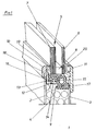
- Fig. 1 a section through an edge of an opening in a door panel 1 is shown, which is part of a door leaf not further explained.
- the side of the door leaf at risk of break-in is included eS "and faces the left margin of the drawing.
- the inside facing a building is marked with iS ". It faces the right edge of the drawing.
- the door panel 1 consists of a sheet metal on both sides 2 and 3 laminated core 4.
- the core 4 is a Insulating material, e.g. B. a rigid foam.
- Sheets 2 and 3 are preferably aluminum sheets.
- In the door panel 1 is an opening not shown here cut into which a sealing glazing 5 with Inner pane 6 and outer pane 7 is set. Between Inner pane 6 and outer pane 7 are one circumferential spacer bar 8, so that one in the usual Double glazing is available.
- the core 4 of the door panel 1 is milled out between the sheets 2 and 3 with an approximately central shoulder 9, so that in these certain edge areas the sheets 2 and 3 over the exposed outer edge or the free reveal surface of the core 4 around project a predetermined amount.
- Decorative profiles 10 and 11 surround the edge of the opening and hold the glazing 5.
- the decorative profiles 10 and 11 are designed as plug-in strips which can be plugged onto the free edges of the associated sheets 2 and 3 by having a plug-in receptacle in the form of a longitudinal groove on their underside, whose groove width is approximately equal to the thickness of the sheet 2 or 3 received in the groove.
- Decorative profiles 10 located on the door panel each have a higher groove flank in the rear, the endangered side
- the higher groove flank forms a support and anchoring element 12 in one piece with the decorative profile 10 because it is integrally formed thereon in the form of an angular extension of the decorative profile 10.
- the second leg 14 runs approximately parallel to the free surface of the core 4 and has an anchor foot 15 which engages in a recess provided in a reinforcing body 16, as shown here
- the reinforcing body is an approximately Z-shaped profile made of plastic, which is placed in front of the free surface of the core 4 so that it underpins the glazing 5 and in the installed position the angular extension 12 and thus also the decorative profile 10 in the region of the edge of the
- the opening in the door panel 1 is locked in a form-fitting manner rpers 16 this can also be seen from the inside iS "of the door panel 1 from screws 17 driven through the sheet metal 3.
- the reinforcing body can also be glued in. The screws 17 are hidden by the decorative profile 11 which is then fitted on the inside.
- Fig. 1 illustrates that there are further bonds are.
- the decorative profiles 10 and 11 and the glazing 5 can still in the corresponding grooves of the decorative profiles held seals 19 and 20 made of elastic material be set.
- FIG. 1 illustrates that all parts of the component set, including the glazing, the burglar-resistant effect more or less are involved once the opening in the door panel 1 with glazing Decorative profiles edged and mounted in the opening.
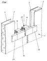
- Fig. 2 indicates an embodiment in which a Component set is used, the formation of a Corner without miter cuts. This is accomplished through corner fillers 21 and 22 which, like that Decorative profile 10, on the free edges of the sheet 2 are pluggable.
- the decorative profile 10 and of course other decorative profiles that are part of the Components are set, for example the decorative profiles 11, which can be plugged onto the sheet 3, can the use of corner fillers 21, 22 by simple straight and transverse cuts are cut to length.
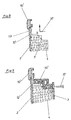
- Fig. 3 shows a view of a corner filler 21.
- This is a molded part, preferably made of aluminum, which as plate-like block is formed, at least has a slot 23 in the respective, in the corner abutting block edge surfaces 24 and 25 is arranged and thus approximately around the plate corner 26 runs.
- each slot 23 is approximately equal to the thickness of a sheet 2 or 3.
- Each slot 23 can, as it is shown here by way of example, by different heights Groove edges 27 and 28 may be limited.
- Fig. 4 shows a second embodiment of a corner filler 21 ', which can be used for a corner that is not is rectangular.
- Fig. 5 the equipment of a circular opening is in the door panel 1 with appropriately designed parts of the Component set shown in section. Same Components are identified by the same reference numbers.
- the support and Anchoring element is a for this version Profile ring 10 'separate component 12'.
- the Reinforcing body is also in the form of a ring before, but has the same profile cross-section as it also exists in the reinforcing body according to FIG. 1 is.
- Fig. 6 shows a sectional view of the Decorative profile ring 10 'and the support and Anchoring member 12 ', on the first angle leg 13 here the decorative profile ring 10 'is inserted. At this The design profile ring 10 'overlaps with a molded nose 29 the sheet 2 of the door panel 1.
- Fig. 7 is a view of the door panel 1 with the incised circular opening 30 shown.
- the in the opening 30 protruding edge edges 31 of the Sheets 3 are regularly distributed over the circumference arranged notches 32 provided.
- the decorative profile ring 11 ' which with its shorter groove 33 the free Should overlap the edge of the sheet 3 (see FIG. 5) points to the notches 32 congruent notches 34 on.
- the decorative profile ring 11 is, as is schematic here is indicated by the arrow 35 in the opening 30 of used outside, which enables the notches.
- Fig. 8 shows a schematic sectional view of the edge the opening 30 in the door panel 1 on the side of the Sheet 2 (Fig. 5).
- the support and anchoring member 12 ' which is in the form of a section, here half Profile ring, present, can from the inside towards the Arrow 37 horizontally over the again with a paragraph 9 milled free surface of the core 4 pushed until the first angle leg 13 on the inside of the sheet 2 strikes. Then the support and Anchoring member 12 'perpendicular upwards to the center of the circular opening 30 are moved so that his leg 13 into a slot of the decorative profile ring 10 'inserts, as shown in Fig. 9.
Landscapes
- Engineering & Computer Science (AREA)
- Civil Engineering (AREA)
- Structural Engineering (AREA)
- Securing Of Glass Panes Or The Like (AREA)
- Wing Frames And Configurations (AREA)
- Elevator Door Apparatuses (AREA)
Abstract
Description
Die Erfindung betrifft einen Bauelementensatz zur einbruchhemmenden Ausgestaltung einer Öffnung in einer Türfüllung eines Türblattes, umfassend Zierprofile zur Einfassung der Ränder der mittels Verglasung oder dergleichen Plattenteil dichtsetzbaren Öffnung in der aus beidseitig mit Blech kaschiertem Kern bestehenden Türfüllung, wobei die Bleche im Bereich der Ränder über die freie Leibungsfläche des Kerns in die Öffnung um ein vorbestimmtes Maß vorstehen, so daß die über eine Steckaufnahme in Form einer Längsnut verfügenden Zierprofile auf formschlüssig in die jeweilige Längsnut eingreifende Kanten von in die Öffnung vorstehenden Teilen, insbesondere die freien Kanten der Bleche, steckbar sind, sowie vor die im Bereich der Ränder befindliche Leibungfläche der Öffnung im Kern setzbare Verstärkungskörper in Form von Profilleisten, wobei zumindest die jeweils an der einbruchgefährdeten Türaußenseite anzubringenden Zierprofile und die entsprechend zugeordneten Verstärkungskörper gegenseitig in formschlüssigen Eingriff bringbare Riegelorgane aufweisen.The invention relates to a set of components for burglar-resistant design of an opening in a Door panel of a door leaf, including decorative profiles for Edging the edges of the glazing or same plate part sealable opening in the existing core laminated on both sides with sheet metal Door panel, with the sheets over the edges the free reveal surface of the core into the opening around project a predetermined dimension, so that the one Plug receptacle in the form of a longitudinal groove Decorative profiles in a form-fitting manner in the respective longitudinal groove engaging edges of protruding into the opening Parts, especially the free edges of the sheets, are pluggable, as well as in front of the edges located reveal surface of the opening in the core Reinforcing body in the form of profile strips, where at least the one at risk of burglary Decorative profiles to be attached to the outside of the door and the mutually corresponding reinforcing body locking elements that can be brought into positive engagement exhibit.
Öffnung in Türfüllungen werden mit Zierprofilen eingefaßt, die eine nicht vermeidbare Fuge zwischen dem Außenrand der Verglasung und dem Rand der Öffnung abdecken und gleichzeitig sowohl Verglasung als auch Türfüllung einklemmend halten. Dabei soll die aus Zierprofilen letztlich zusammengesetzte Einfassung einen Rahmen mit optisch ansprechendem Äußeren bilden. Opening in door panels are with decorative profiles bordered that an unavoidable joint between the The outer edge of the glazing and the edge of the opening cover and at the same time both glazing as well Keep the door panel trapped. The should Ornamental profiles ultimately composite edging one Form a frame with a visually appealing exterior.
Die Einfassung mit Zierprofilen im Bereich der Fuge stellt einen Schwachpunkt hinsichtlich der Einbruchhemmung dar, weil nach Entfernen zumindest des von der Außenseite, also der einbruchgefährdeten Seite, her zugänglichen Rahmens aus Zierprofilen, die Verglasung theoretisch herausnehmbar wäre und durch die dann freie Öffnung in der Türfüllung ein unbefugtes Öffnen der Tür möglich wäre.The border with decorative profiles in the area of the joint represents a weak point in terms of Burglar resistance because after removing at least the from the outside, i.e. the side at risk of burglary, accessible frame made of decorative profiles, the glazing would be theoretically removable and then free Opening in the door panel an unauthorized opening of the door it is possible.
Es sind verschiedene Maßnahmen bereits vorgeschlagen worden, um das Entfernen der Zierprofile zu erschweren, und damit die Öffnung in einer Türfüllung einbruchhemmend zu gestalten.Various measures have already been proposed to make it difficult to remove the decorative profiles, and thus the opening in a door panel is burglar-resistant to design.
Es hat sich gezeigt, daß die vorgeschlagenen Maßnahmen zur Erreichung der einbruchhemmenden Wirkung, abgesehen von der Bereitstellung zusätzlicher Bauteile, insbesondere die Montage komplizieren und damit eine Tür verteuern.It has been shown that the proposed measures to achieve the burglar-resistant effect, apart from the provision of additional components, especially complicate the assembly and thus a door make it more expensive.
Die Notwendigkeit, Verglasungen gegebenenfalls austauschen zu können, zwingt darüber hinaus dazu, auch die Demontage möglichst einfach zu gestalten.The need for glazing if necessary to be able to exchange also forces to to make disassembly as easy as possible.
Die Öffnungen in einer Türfüllung eines Türblattes sind zumeist durch gerade verlaufende Ränder begrenzt. Dies erfordert, die Zierprofile im Bereich der Ecken, dort wo die Zierprofile aneinanderstoßen, auf Gehrung zu schneiden. Dies bedingt insbesondere bei einer Serienfertigung genaueste Berechnungen der Längen der einzelnen Zierprofile und bedeutet, daß in der Praxis für jede Öffnung in einer Türfüllung eine jeweils zugehörige neue Berechnung der Längen und der Gehrungsschnitte zu erfolgen hat, was sich ungünstig auf die Gesamtherstellungskosten für eine Tür auswirkt, da auf vorgefertigte Serienteile zumeist nicht zurückgegriffen werden kann.The openings in a door panel of a door leaf are mostly delimited by straight edges. This requires the decorative profiles in the area of the corners, wherever butt the decorative profiles together, towards miter to cut. This is particularly important for one Series production most accurate calculations of the lengths of the individual decorative profiles and means that in practice for each opening in a door panel has a corresponding one new calculation of lengths and miter cuts has been done, which has an adverse effect on the total manufacturing costs impact for a door on there prefabricated series parts mostly not used can be.
Eine einfache Montage bieten Zierprofile, die über Steckaufnahmen verfügen und im Bereich der Öffnung in einer Türfüllung an entsprechend vorstehenden Teilen durch Aufstecken befestigt werden können. Ein solcher Steckvorgang hat jedoch den Nachteil, daß die mit Gehrung zugeschnittenen Enden der Zierprofile wieder Probleme aufwerfen, die der Verwendung der Steckmöglichkeiten und damit der einfachen Montage entgegenstehen, zumal dann, wenn eine einbruchhemmende Wirkung gewährleistet sein soll.Decorative profiles are easy to install, using plug-in sockets and in the area of opening in one Door panel on correspondingly protruding parts Can be attached. Such a However, the plugging process has the disadvantage that the miter cut ends of the decorative profiles again problems pose that of using the pluggable and to prevent easy assembly, especially since if a burglar-resistant effect can be guaranteed should.
Der Erfindung liegt die Aufgabe zugrunde, einen Bauelementensatz mit Zierprofilen zur Einfassung der Ränder einer mittels Verglasung dichtsetzbaren Öffnung in einer Türfüllung eines Türblattes zu schaffen, der durch Steckverbindungen leicht montiert und demontiert werden kann, dabei jedoch gleichzeitig einbruchhemmende Wirkung bietet.The invention has for its object a Component set with decorative profiles for edging the Edges of an opening that can be sealed with glazing in to create a door panel of a door leaf that by Plug connections can be easily assembled and disassembled can, but at the same time burglar-resistant effect offers.
Diese Aufgabe ist erfindungsgemäß durch einen Bauelementensatz gelöst, der zwischen einanderzugekehrte Endseiten der Zierprofile anordbare Eckfüllstücke umfaßt.This object is achieved by one Solved component set that facing between each other End sides of the decorative profiles includes corner fillers.
Die Eckfüllstücke ermöglichen es, die Zierprofile durch quer zur Längsachse geführte gerade Schnitte abzulängen, so daß folglich auf Gehrungsschnitte verzichtet werden kann. Die Eckfüllstücke sind so gestaltet, daß sie sich mit zwei Außenkantenflächen an die Schnittflächen an den stirnseitigen Enden der Zierprofile anschmiegen, sobald sie in die Ecken der Öffnungen gesetzt sind und die entsprechenden Zierprofile mittels einer Steckverbindung als Einfassung der Ränder der Öffnung so montiert sind,The corner fillers allow the decorative profiles to pass through to cut straight cuts transverse to the longitudinal axis, so that miter cuts are consequently dispensed with can. The corner fillers are designed so that they are with two outer edge surfaces on the cut surfaces on the nestle the front ends of the decorative profiles as soon as they are placed in the corners of the openings and the corresponding decorative profiles by means of a plug connection are mounted as a border around the edges of the opening,
daß sie gleichzeitig auch die Verglasung halten.
Die Eckfüllstücke können mit Vorteil an ihrer
sichtseitigen Oberfläche in unterschiedlichen Farben und
Formen gestaltet sein, wodurch sich das optische
Erscheinungsbild einer Tür sowohl an ihrer Außenseite als
auch an ihrer Innenseite variieren und beliebig gestalten
läßt.that they also hold the glazing at the same time.
The corner filler pieces can advantageously be designed on their visible surface in different colors and shapes, which means that the visual appearance of a door can be varied and designed as desired both on the outside and on the inside.
Jedes Eckfüllstück ist mit Vorteil ein auf die jeweiligen Kanten, die in einer Ecke der Öffnung zusammenlaufen, steckbares Formteil. Dabei können die Kanten sowohl die Kanten der Bleche sein, mit denen der Kern kaschiert ist. Es kann jedoch auch ein besonderes Teil vorgesehen sein, auf welches jeweils ein zugeordnetes Eckfüllstück gesteckt werden kann. Damit sind auch die Eckfüllstücke leicht montierbar. Jedes als Eckfüllstück dienende Formteil ist nach einer Weiterbildung als plattenähnlicher Klotz ausgebildet, der wenigstens eine Stecknut hat, die in den jeweiligen, in der Klotz-Ecke aneinanderstoßenden Klotz-Kantenflächen angeordnet ist.Each corner filler is advantageous to the respective one Edges converging in a corner of the opening pluggable molded part. The edges can both Edges of the sheets with which the core is laminated. However, a special part can also be provided, on each of which an assigned corner filler can be inserted. This also includes the corner filler pieces easy to assemble. Each serving as a corner filler Molding is after a training as plate-like block formed, the at least one Stecknut has that in the respective, in the block corner abutting block edge surfaces is arranged.
Die Stecknuten sind so dimensioniert, daß ihre Nutbreite etwa gleich der Dicke eines Bleches ist.The slots are dimensioned so that their slot width is approximately equal to the thickness of a sheet.
Vorzugsweise ist jede Stecknut durch unterschiedlich hohe Nutflanken begrenzt. Dabei ist die Anordnung derart getroffen, daß die Nutflanke, welche den jeweiligen Außenseiten der Türfüllung zugekehrt ist, die höhere Nutflanke ist, die also ein Blech oder ein dem Blech entsprechendes Bauteil in der aufgesteckten Position übergreift. Each insertion groove is preferably of different heights Groove flanks limited. The arrangement is such hit that the groove flank, which the respective Outside of the door panel is facing, the higher Is the flank of the groove, that is a sheet or a sheet corresponding component in the attached position spreads.
Diese Ausgestaltung ist vorzugsweise auch bei den Zierprofilen vorgesehen und hat den Vorteil, daß die Einstecktiefe bei der Montage gegebenenfalls noch variiert werden kann. Außerdem sind die von außen sichtbaren Flächen der Eckfüllstücke und entsprechend auch der Zierleisten größer und damit geeignet, darauf entsprechende Profilierungen, Formgebungen und sonstige das optische Aussehen beeinflussende Gestaltungsmaßnahmen anzubringen.This configuration is preferably also in the Decorative profiles provided and has the advantage that the Insertion depth during assembly if necessary can be varied. They are also from the outside visible areas of the corner filler and accordingly also the moldings are larger and therefore suitable on it corresponding profiles, shapes and other design measures influencing the visual appearance to attach.
Steckverbindungen lassen sich dann, wenn der Stecksitz nicht besonders stramm ausgestaltet ist, relativ leicht wieder lösen. Um dennoch einbruchhemmende Wirkung zu erreichen, ist vorgesehen, daß ein das zugeordnete Blech insbesondere das an der einbruchgefährdeten Außenseite befindliche Blech hinterfangendes Stütz- und Verankerungsorgan vorgesehen. Das Stütz- und Verankerungsorgan hält die an der einbruchgefährdeten Außenseite befindlichen aufgesteckten Zierprofile in der Steckposition, womit auch die zwischengesetzten Eckfüllstücke, die ebenfalls gesteckt sind, gesichert sind, da sie sich aus dem aus dem von den Zierprofilen gebildeten Rahmen nicht mehr herausnehmen lassen. Dies wäre nur dann möglich, wenn zumindest eines der breiten, jeweils an ein Eckfüllstück anstoßenden Zierprofile abgenommen ist. Jedes Stütz- und Verankerungsorgan ist vorzugsweise ein Profil, das einen ersten Profilschenkel aufweist, der an die Rückseitenfläche des zugeordneten Blechs anlegbar ist und dabei über den freien Blechrand vorstehend, in die Längsnut des zugeordneten Zierprofils ragt. Plug connections can be made when the plug seat is not particularly tight, relatively light solve again. To nonetheless burglar-resistant effect achieve, it is provided that the assigned sheet especially that on the outside, which is at risk of break-in located sheet metal backing support and Anchoring device provided. The support and Anchoring organ keeps those at risk of burglary Attached decorative profiles in the outside Plug position, with which the intermediate ones Corner filler pieces, which are also inserted, secured are because they are made from the from the decorative profiles no longer allow the formed frame to be removed. This would only be possible if at least one of the broad, decorative profiles each abutting a corner filler is decreased. Every support and anchoring organ is preferably a profile that has a first profile leg has, which on the back surface of the associated Sheet can be put on and over the free edge of the sheet above, in the longitudinal groove of the associated decorative profile protrudes.
Darüber hinaus weist jedes Stütz- und Verankerungsorgan einen gegen das gegenüberliegende Blech vorstehenden zweiten Profilschenkel auf, der den eingesetzten Verstärkungskörper teilweise untergreift und um Formschlußelemente verfügt, die mit entsprechenden Gegenelementen des zugeordneten Verstärkungskörpers verankerbar sind.In addition, each support and anchoring element one protruding against the opposite sheet second profile leg on which the inserted Reinforcement body partially under and around Has positive locking elements with corresponding Counter elements of the associated reinforcing body can be anchored.
Der Verstärkungskörper kann ein Kunststoffprofil sein, welches in vorteilhafter Weise zusätzlich auch als thermische Isolation wirkt und das auf entsprechende Länge geschnitten wird, so daß es in die Öffnung in der Türfüllung so einlegbar ist, daß es die freie Leibungsfläche der Öffnung, also die freiliegende Oberfläche des Kerns im Bereich der Öffnung abdeckt. Das Stütz- und Verankerungsorgan kann ein separates Bauteil sein. Es kann jedoch auch an das Zierprofil, und zwar an dessen die Längsnut begrenzenden Schenkel, angeformt sein. Beide Bauteile, das Stütz- und Verankerungsorgan einerseits und der Verstärkungskörper andererseits verriegeln einander in quer zur Ebene der Türfüllung verlaufender Richtung, so daß die Einbruchhemmung gegeben ist, sobald die Verglasung eingesetzt ist. Die Verglasung ist dabei so dimensioniert, daß sie mit ihren Außenrändern auf den dem jeweiligen Außenrand zugeordneten Verstärkungskörper in etwa aufliegt bzw. nur noch wenig Abstand besteht. Der Verstärkungskörper kann deshalb nicht mehr ohne weiteres bei einem Einbruchsversuch hochgehebelt werden.The reinforcing body can be a plastic profile, which also advantageously as thermal insulation works on the corresponding Length is cut so that it fits into the opening in the Door panel can be inserted so that it is free Reveal surface of the opening, i.e. the exposed one Covering the surface of the core in the area of the opening. The Support and anchoring element can be a separate component his. However, it can also be attached to the decorative profile whose leg defining the longitudinal groove is formed his. Both components, the support and anchoring element on the one hand and the reinforcing body on the other lock each other in across the plane of the door panel extending direction, so that the burglar resistance is given is as soon as the glazing is installed. The glazing is dimensioned so that it with their Outer edges on the assigned to the respective outer edge Reinforcement body rests approximately or only there is little distance. The reinforcing body can therefore no longer with one Burglary attempt to be levered up.
Ein Abhebeln kann noch weiter dadurch erschwert werden, daß, von der Innenseite aus, der Verstärkungskörper mit dem jeweils zugeordneten Innenblech verschraubt wird. Die Verschraubungen sind nicht mehr sichtbar, sobald das innenseitig vorgesehene Zierprofil aufgesteckt ist, weil dessen höherer Nutschenkel dann die Schrauben abdeckt.Prying it off can be made even more difficult by that, from the inside, the reinforcing body with is screwed to the respective assigned inner panel. The Screw connections are no longer visible as soon as that the decorative profile provided on the inside is attached because whose higher groove leg then covers the screws.
Ist das Stütz- und Verankerungsorgan ein besonderes Bauteil, kann es mit der Rückseitenfläche des jeweils zugeordneten Blechs verklebt werden. Die Zierprofile und die Eckfüllstücke können zur Montage dann mit Vorteil aufgesteckt und in die Endposition gerückt werden. Anschließend wird das Stütz- und Verankerungsorgan eingesetzt und so in Richtung zum Zentrum der Öffnung geschoben, daß es mit der entsprechend zugeordneten Kante in die Stecknut von Zierprofil bzw. Eckfüllstück eingreift. In dieser Position kann das Stütz- und Verankerungsorgan dann mit dem Blech verklebt werden.The support and anchoring organ is a special one Component, it can match the back surface of each associated sheet are glued. The decorative profiles and the corner filler pieces can then be used for assembly attached and moved to the end position. Then the support and anchoring element inserted and so towards the center of the opening pushed that it with the correspondingly assigned edge into the slot of the decorative profile or corner filler intervenes. In this position the support and Anchoring element can then be glued to the sheet.
Diese Ausgestaltung mit einem separaten Stütz- und Verankerungsorgan, das verklebt oder auf andere Art und Weise in bestimmten Positionen mit dem Blech verbindbar ist, eignet sich besonders zur Einfassung einer kreisförmigen Öffnung mit Zierprofilringen, wobei das Stütz- und Verankerungsorgan dann zur leichteren Montage aus mehreren Kreisringabschnitten zusammengesetzt werden kann.This configuration with a separate support and anchoring element, that glued or otherwise and Can be connected to the sheet in certain positions is particularly suitable for edging one circular opening with decorative profile rings, the Support and anchoring element then for easier assembly be composed of several circular ring sections can.
Auch ein Zierprofilring kann den Ringabschnitten bestehen. Dabei können, falls gewünscht, zwischen Ringabschnitte wieder entsprechend gestaltete Eckfüllstücke gesetzt werden.Even a decorative profile ring can the ring sections consist. If desired, you can choose between ring sections again appropriately designed corner filler pieces be set.
Eine Montageerleichterung wird des weiteren dadurch
erreicht, daß das der einbruchgefährdeten Außenseite
gegenüberliegende und somit an der Innenseite befindliche
Blech, Randausklinkungen aufweist und daß jeder
zugeordnete Zierprofilring eine Stecknut aufweist, deren
innen liegende, das Blech hintergreifende Nutflanken mit
den Randausklinkungen kongruente Ausklinkungen aufweisen,
wodurch zwischen Zierprofilring und Blech eine Art
![]()
![]()
Dies erlaubt es, den innenseitigen Zierprofilring anzusetzen und durch Drehen um sein Ringzentrum am Blech festzusetzen.This allows the inside decorative profile ring and by rotating it around its ring center on the sheet to fix.
Die Zierprofile und Eckfüllstücke sind mit Vorteil aus dem Werkstoff Aluminium gefertigt. Selbstverständlich läßt sich auch Kunststoff einsetzen. Auch die Verstärkungskörper sowie die Stütz- und Verankerungsorgane lassen sich sowohl aus Metall als auch aus Kunststoff herstellen und vorfertigen. Aus Festigkeitsgründen ist jedoch für jedes Stütz- und Verankerungsorgan ein metallischer Werkstoff zu bevorzugen.The decorative profiles and corner filler pieces are advantageous made of aluminum. Of course plastic can also be used. Also the Reinforcing body and the support and Anchoring elements can be made of metal as well manufacture and prefabricate from plastic. Out Strength reasons, however, is for every support and Anchoring member too a metallic material prefer.
Ausführungsbeispiele der Erfindung, aus denen sich weitere erfinderische Merkmale ergeben, sind in der Zeichnung dargestellt. Es zeigen:
- Fig. 1
- eine Schnittansicht eines Randes einer Öffnung in einer Türfüllung, ausgerüstet mit komplett montiertem Bauelementensatz,
- Fig. 2
- eine schematisch dargestellte Teilansicht eines unteren Bereichs einer Öffnung in einer Türfüllung mit einem Teil der Elemente des Bauelementensatzes,
- Fig. 3
- eine Ansicht einer Ausführung eines Eckfüllstückes des Bauelementensatz,
- Fig. 4
- eine Ansicht einer anderen Ausführungsform eines Eckfüllstückes des Bauelementensatzes,
- Fig. 5
- eine Schnittansicht des Randes einer kreisrunden Öffnung in einer Türfüllung, ausgerüstet mit einem entsprechenden Bauelementensatz
- Fig. 6
- eine Schnittansicht eines Zierprofils mit separatem Stütz- und Verankerungsorgan in der Ausführung zur Ausrüstung der kreisrunden Öffnung gemäß Fig. 5
- Fig. 7
- eine schematische Ansicht einer Türfüllung mit kreisrunder Öffnung und daran ansetzbarem Zierprofilring des Bauelementensatzes
- Fig. 8
- einen Teilschnitt einer Seite des Randes einer kreisrunden Öffnung in einer Türfüllung mit angesetztem Zierprofilring sowie separatem Stütz- und Verankerungsorgan und
- Fig. 9
- eine Ansicht entsprechend Fig. 8 mit in verriegelnder Endposition befindlichem Stütz- und Verankerungsorgan sowie das Stütz- und Verankerungsorgan wiederum fixierendem ringförmigen Verstärkungskörper
- Fig. 1
- 1 shows a sectional view of an edge of an opening in a door panel, equipped with a completely assembled component set,
- Fig. 2
- 2 shows a schematically illustrated partial view of a lower region of an opening in a door panel with part of the elements of the component set,
- Fig. 3
- 2 shows a view of an embodiment of a corner filler of the component set,
- Fig. 4
- 2 shows a view of another embodiment of a corner filler of the component set,
- Fig. 5
- a sectional view of the edge of a circular opening in a door panel, equipped with a corresponding set of components
- Fig. 6
- 5 shows a sectional view of an ornamental profile with a separate support and anchoring element in the embodiment for equipping the circular opening according to FIG. 5
- Fig. 7
- is a schematic view of a door panel with a circular opening and attachable decorative profile ring of the component set
- Fig. 8
- a partial section of one side of the edge of a circular opening in a door panel with attached decorative profile ring and separate support and anchoring member and
- Fig. 9
- a view corresponding to FIG. 8 with the supporting and anchoring member located in the locking end position and the annular reinforcing body in turn fixing the supporting and anchoring member
In Fig. 1 ist ein Schnitt durch einen Rand einer Öffnung
in einer Türfüllung 1 dargestellt, die Teil eines nicht
weiter erläuterten Türblattes ist. Die einbruchgefährdete
Seite des Türblattes ist mit
Die Türfüllung 1 besteht aus einem beidseitig mit Blechen
2 und 3 kaschierten Kern 4. Der Kern 4 ist ein
Isoliermaterial, z. B. ein Hartschaum. Die Bleche 2 und 3
sind vorzugsweise Aluminiumbleche. In die Türfüllung 1
ist eine hier nicht weiter dargestellte Öffnung
geschnitten, in die eine verschließende Verglasung 5 mit
Innenscheibe 6 und Außenscheibe 7 gesetzt ist. Zwischen
Innenscheibe 6 und Außenscheibe 7 befindet sich eine
umlaufende Abstandsleiste 8, so daß eine in üblicher
Bauart ausgebildete Doppelverglasung vorliegt.The
In vorbestimmten Randbereichen ist der Kern 4 der
Türfüllung 1 zwischen den Blechen 2 und 3 mit einem etwa
mittigen Absatz 9 herausgefräst, so daß in diesen
bestimmten Randbereichen die Bleche 2 und 3 über den frei
liegenden Außenrand, bzw. die freie Leibungsfläche des
Kerns 4 um ein vorbestimmtes Maß vorstehen. Zierprofile
10 und 11 fassen den Rand der Öffnung ein und halten die
Verglasung 5. Die Zierprofile 10 und 11 sind als auf die
freien Kanten der zugeordneten Bleche 2 und 3 steckbare
Steckleisten ausgebildet, indem sie an ihrer Unterseite
eine Steckaufnahme in Form einer Längsnut aufweisen,
deren Nutbreite etwa gleich der Dicke des in der Nut
aufgenommen Bleches 2 bzw. 3 ist. Jeweils an der
einbruchgefährdeten Seite
Fig. 1 verdeutlicht, daß weitere Verklebungen vorhanden
sind. Insbesondere ist der Verstärkungskörper 16 mit der
Verglasung über eine Klebstofflage 18 verklebt.
Zwischen die Zierprofile 10 und 11 sowie die Verglasung 5
können noch in entsprechenden Nuten der Zierprofile
gehaltene Dichtungen 19 und 20 aus elastischem Material
gesetzt werden. Fig. 1 illustrates that there are further bonds
are. In particular, the reinforcing
Das Ausführungsbeispiel gemäß Fig. 1 verdeutlicht, daß
sämtliche Teile des Bauelementensatzes, einschließlich
der Verglasung, an der einbruchhemmenden Wirkung mehr
oder weniger beteiligt sind, sobald die die Öffnung in
der Türfüllung 1 verschließende Verglasung mit
Zierprofilen eingefaßt und in der Öffnung montiert ist.The embodiment of FIG. 1 illustrates that
all parts of the component set, including
the glazing, the burglar-resistant effect more
or less are involved once the opening in
the
Dadurch, daß die Zierprofile 10, 11 mit Stecknuten ausgerüstet
sind, lassen sie sich zwar relativ einfach durch
Auf-stecken auf die freien Kanten der Bleche 2 und 3
montieren. Für die einwandfreie Eckausbildung von durch
die Zierleisten gebildeten Rahmen zur Einfassung der
Ränder einer eckigen Öffnung in der Türfüllung ist das
dafür erforderliche Schneiden bzw. Ablängen der
Zierprofile mit Gehrungsschnitt jedoch nicht
unproblematisch, denn durch das Aufstecken werden die
Zierprofile so verschoben, daß sich die Rahmennennweite
ändert und damit mehr oder weniger breite Stoßfugen in
den Ecken der aus Zierprofilen zu bildenden Rahmen
entstehen.Characterized in that the
Fig. 2 deutet eine Ausführung an, bei der ein
Bauelementensatz verwendet wird, der das Ausbilden einer
Ecke ohne Gehrungsschnitte ermöglicht. Dies wird erreicht
durch Eckfüllstücke 21 und 22, die, ebenso wie das
Zierprofil 10, auf die freien Kanten des Blechs 2
steckbar sind. Das Zierprofil 10 und selbstverständlich
auch andere Zierprofile, die Bestandteil des
Bauelementensatzes sind, beispielsweise die Zierprofile
11, welche auf das Blech 3 steckbar sind, können aufgrund
der Verwendung von Eckfüllstücken 21, 22 durch einfache
gerade und quer verlaufende Schnitte abgelängt werden.
Sobald das Zierprofil 10 und die beiden Eckfüllstücke 21,
22 auf das Blech 2 im Bereich des unteren Querrandes der
Öffnung in der Türfüllung 1 gesteckt sind, kann der hier
schematisch angedeutete Verstärkungskörper 16 in Richtung
des strichpunktierten Pfeils 23 eingesetzt werden, so daß
der Verstärkungskörper das Zierprofil 10 formschlüssig
verriegelt bzw. fixiert, wie es in Fig. 1 dargestellt
ist.Fig. 2 indicates an embodiment in which a
Component set is used, the formation of a
Corner without miter cuts. This is accomplished
through
Fig. 3 zeigt eine Ansicht eines Eckfüllstückes 21. Dieses
ist ein Formteil, vorzugsweise aus Aluminium, das als
plattenähnlicher Klotz ausgebildet ist, der wenigstens
eine Stecknut 23 hat, die in den jeweiligen, in der Ecke
aneinanderstoßenden Klotz- Kantenflächen 24 und 25
angeordnet ist und somit in etwa um die Plattenecke 26
verläuft.Fig. 3 shows a view of a
Die Nutbreite jeder Stecknut 23 ist etwa gleich der Dicke
eines Bleches 2 bzw. 3. Jede Stecknut 23 kann, wie es
hier beispielhaft gezeigt ist, durch unterschiedlich hohe
Nutflanken 27 und 28 begrenzt sein.The slot width of each
Fig. 4 zeigt eine zweite Ausführung eines Eckfüllstückes 21', welches für eine Ecke verwendbar ist, die nicht rechtwinkelig ist.Fig. 4 shows a second embodiment of a corner filler 21 ', which can be used for a corner that is not is rectangular.
In Fig. 5 ist die Ausrüstung einer kreisrunden Öffnung in
der Türfüllung 1 mit entsprechend gestalteten Teilen des
Bauelementensatzes im Schnitt dargestellt. Gleiche
Bauteile sind mit gleichen Bezugszahlen bezeichnet.In Fig. 5 the equipment of a circular opening is in
the
Bei diesem Ausführungsbeispiel sind die Zierprofile 10' und 11' als Ringe ausgebildet. Das Stütz- und Verankerungsorgan ist bei dieser Ausführung ein zum Profilring 10' separates Bauteil 12' . Das Bauteil 12', das die Funktion des Stütz- und Verankerungsorgans gemäß Fig. 1 erfüllt, liegt hier ebenfalls als Profilring vor, der zur Erleichterung der Montage geteilt ist, also z. B. aus zwei Kreisring-Hälften besteht. Der Verstärkungskörper liegt ebenfalls in Form eines Ringes vor, weist jedoch den gleichen Profilquerschnitt auf, wie er auch bei dem Verstärkungskörper gemäß Fig. 1 vorhanden ist.In this embodiment, the decorative profiles 10 ' and 11 'formed as rings. The support and Anchoring element is a for this version Profile ring 10 'separate component 12'. The component 12 ', that the function of the support and anchoring organ according 1 is also present as a profile ring, which is divided to facilitate assembly, e.g. B. consists of two halves of a circular ring. The Reinforcing body is also in the form of a ring before, but has the same profile cross-section as it also exists in the reinforcing body according to FIG. 1 is.
Fig. 6 zeigt noch einmal eine Schnittansicht des
Zierprofil-Ringes 10' und des Stütz- und
Verankerungsorgans 12', auf dessen ersten Winkelschenkel
13 hier der Zierprofil-Ring 10' gesteckt ist. Bei dieser
Ausführung übergreift der Zierprofil-Ring 10'mit einer
angeformten Nase 29 das Blech 2 der Türfüllung 1.Fig. 6 shows a sectional view of the
Decorative profile ring 10 'and the support and
Anchoring member 12 ', on the
In Fig. 7 ist eine Ansicht der Türfüllung 1 mit der
eingeschnittenen kreisrunden Öffnung 30 dargestellt. Die
in die Öffnung 30 vorstehenden Kantenränder 31 des
Bleches 3 sind mit regelmäßig über den Umfang verteilt
angeordneten Ausklinkungen 32 versehen. Der Zierprofil-Ring
11', der mit seiner kürzeren Nutflanke 33 den freien
Kantenrand des Bleches 3 übergreifen soll (s. Fig. 5)
weist zu den Ausklinkungen 32 kongruente Ausklinkungen 34
auf. Der Zierprofil-Ring 11 wird, wie es hier schematisch
durch den Pfeil 35 angedeutet ist, in die Öffnung 30 von
außen eingesetzt, was die Ausklinkungen ermöglichen.
Danach kann der aufliegende bzw. eingesetzte Zierprofil-Ring
11' in Richtung des Pfeils 36 gedreht werden,
wodurch sich die Nutflanke 33 des Zierprofil-Ringes 11'
unter den nicht ausgeklinkten Kantenrand 31 des Bleches 3
schiebt. Der Zierprofil-Ring 11' ist dadurch in der
Öffnung 30 verriegelt bzw. festgesetzt. In Fig. 7 is a view of the
Fig. 8 zeigt eine schematische Schnittansicht des Randes
der Öffnung 30 in der Türfüllung 1 an der Seite des
Bleches 2 (Fig. 5). Das Stütz- und Verankerungsorgan 12',
welches in Form eines Abschnittes, hier eines halben
Profilringes, vorliegt, kann von innen in Richtung des
Pfeils 37 waagerecht über die wieder mit einem Absatz 9
ausgefräste freie Oberfläche des Kerns 4 geschoben
werden, bis der erste Winkelschenkel 13 an der Innenseite
des Bleches 2 anschlägt. Anschließend kann das Stütz- und
Verankerungsorgan 12' senkrecht nach oben zum Zentrum der
kreisförmigen Öffnung 30 hin bewegt werden, so daß sich
sein Schenkel 13 in eine Stecknut des Zierprofil-Ringes
10' einschiebt, wie es in Fig. 9 dargestellt ist. In
dieser Position kann das Stütz- und Verankerungsorgan 12'
mit der Innenfläche des Bleches 2 und auch mit der freien
Oberfläche des Kerns 4 verklebt und damit fixiert werden.
Anschließend kann der Verstärkungskörper 16', der hier in
Form eines Profilringes vorliegt, eingesetzt werden und
die Formschlußverbindung mit dem Stütz- und
Verankerungsorgan 12', wie sie bereits bei Fig. 1 näher
erläutert wurde, bewirken.Fig. 8 shows a schematic sectional view of the edge
the
Claims (11)
gekennzeichnet durch
zwischen einander zugekehrte Endseiten der Zierprofile (10, 11; 10', 11') anordbare Eckfüllstücke (21, 21', 22).Component set for burglar-resistant design of an opening in a door panel of a door leaf comprising decorative profiles for edging the edges of the opening which can be sealed by means of glazing or similar plate part in the door panel consisting of a core laminated with sheet metal on both sides, the sheets in the area of the edges over the free reveal surface of the core in protrude the opening by a predetermined amount, so that the decorative profiles, which have a plug-in receptacle in the form of a longitudinal groove, can be plugged onto positively engaging edges in the respective longitudinal groove of parts protruding into the opening, in particular the free edges of the sheets, and in front of the area Edge reveal surface of the opening in the core insertable reinforcing body in the form of profile strips, with at least the decorative profiles to be attached to the outside of the door, which are at risk of break-in, and the correspondingly associated reinforcing bodies g have locking elements which can be brought into positive engagement,
marked by
corner filler pieces (21, 21 ', 22) which can be arranged between mutually facing end sides of the decorative profiles (10, 11; 10', 11 ').
Applications Claiming Priority (2)
| Application Number | Priority Date | Filing Date | Title |
|---|---|---|---|
| DE29912177U DE29912177U1 (en) | 1999-07-14 | 1999-07-14 | Set of components for burglar-resistant design of an opening in a door panel of a door leaf |
| DE29912177U | 1999-07-14 |
Publications (3)
| Publication Number | Publication Date |
|---|---|
| EP1069274A2 true EP1069274A2 (en) | 2001-01-17 |
| EP1069274A3 EP1069274A3 (en) | 2002-01-30 |
| EP1069274B1 EP1069274B1 (en) | 2005-12-28 |
Family
ID=8076050
Family Applications (1)
| Application Number | Title | Priority Date | Filing Date |
|---|---|---|---|
| EP00114466A Expired - Lifetime EP1069274B1 (en) | 1999-07-14 | 2000-07-06 | Constructional set for an anti-theft configuration of an opening in a doorleaf panel |
Country Status (3)
| Country | Link |
|---|---|
| EP (1) | EP1069274B1 (en) |
| AT (1) | ATE314552T1 (en) |
| DE (2) | DE29912177U1 (en) |
Cited By (1)
| Publication number | Priority date | Publication date | Assignee | Title |
|---|---|---|---|---|
| EP2274494A4 (en) * | 2008-03-28 | 2015-06-17 | Jeld Wen Sverige Ab | METHOD AND DEVICE FOR INSTALLING DOOR GLASS |
Families Citing this family (2)
| Publication number | Priority date | Publication date | Assignee | Title |
|---|---|---|---|---|
| DE20020038U1 (en) | 2000-11-25 | 2001-03-22 | Kreye, Bernhard, 49080 Osnabrück | Burglar-resistant door leaf |
| DE10200350A1 (en) * | 2002-01-08 | 2003-07-24 | Rodenberg Fenster & Tueren Tec | Door plate with transparent window for security door has decorative frame surrounding window with fastening bolts passing through bores in door plate |
Family Cites Families (4)
| Publication number | Priority date | Publication date | Assignee | Title |
|---|---|---|---|---|
| DE2132799A1 (en) * | 1971-07-01 | 1973-01-11 | Meeth Ernst Josef | DEVICE FOR COVERING THE FRONT EDGES OF TWO ADJACENT GLASS STRIPS IN THE CORNER OF A WINDOW OR DOOR FRAME |
| GB2289708B (en) * | 1992-05-30 | 1996-06-26 | Intron Ltd | Doors and Methods of Forming Doors |
| DE29610168U1 (en) * | 1996-06-10 | 1996-08-22 | Kreye, Bernhard, 49080 Osnabrück | Edging the edges of openings in doors and windows with profiles |
| DE19739147A1 (en) * | 1997-04-02 | 1998-10-08 | Bernhard Kreye | Edging for panes or panels in openings in sheet metal sandwich panels |
-
1999
- 1999-07-14 DE DE29912177U patent/DE29912177U1/en not_active Expired - Lifetime
-
2000
- 2000-07-06 DE DE50011944T patent/DE50011944D1/en not_active Expired - Lifetime
- 2000-07-06 AT AT00114466T patent/ATE314552T1/en not_active IP Right Cessation
- 2000-07-06 EP EP00114466A patent/EP1069274B1/en not_active Expired - Lifetime
Cited By (1)
| Publication number | Priority date | Publication date | Assignee | Title |
|---|---|---|---|---|
| EP2274494A4 (en) * | 2008-03-28 | 2015-06-17 | Jeld Wen Sverige Ab | METHOD AND DEVICE FOR INSTALLING DOOR GLASS |
Also Published As
| Publication number | Publication date |
|---|---|
| EP1069274A3 (en) | 2002-01-30 |
| DE50011944D1 (en) | 2006-02-02 |
| ATE314552T1 (en) | 2006-01-15 |
| EP1069274B1 (en) | 2005-12-28 |
| DE29912177U1 (en) | 2000-04-20 |
Similar Documents
| Publication | Publication Date | Title |
|---|---|---|
| AT402080B (en) | FAÇADE FAIRING FOR THE OUTSIDE OF BUILDINGS | |
| DE3912136C2 (en) | ||
| DE69333450T2 (en) | glazing bar | |
| DE69704552T2 (en) | CONNECTION ARRANGEMENT | |
| DE69026501T2 (en) | WINDOW, DOOR OR SIMILAR LOCKS | |
| EP0760886A1 (en) | FAçADE CONSTRUCTION FOR BUILDINGS | |
| EP0792993B1 (en) | Corner joint for profiles | |
| DE29708214U1 (en) | Door frame | |
| EP1069274B1 (en) | Constructional set for an anti-theft configuration of an opening in a doorleaf panel | |
| DE3223524C2 (en) | Kit for double glazing | |
| DE2609388B2 (en) | Stabilization and alignment element for miter joints between two construction profiles | |
| EP1036908A2 (en) | Door leaf | |
| AT402836B (en) | HOLDING DEVICE FOR PANELS, ESPECIALLY GLASS PANELS, IN CUT-OUTS OF COMPONENTS | |
| DE1953324A1 (en) | Construction system consisting of hollow profile rail elements made of plastic for the production of windows, doors or the like. | |
| DE2423234A1 (en) | FRAMELESS HOUSING | |
| EP1209313B1 (en) | Door leaf designed to inhibit burglary | |
| WO2008148405A1 (en) | Connection molding | |
| CH544210A (en) | Frames made of metal profiles for building elements in the form of doors, windows and walls | |
| EP0342662A1 (en) | Device for assembling decorative screen elements | |
| EP4191012B1 (en) | Building opening closing element and method for producing same | |
| DE2163088A1 (en) | Collapsible flower box - of asbestos cement or concrete having quick corner connectors | |
| DE2913363A1 (en) | Sheet metal window frame - has edges bent in U=shape for engagement by internal clamp | |
| DE19749624C2 (en) | Protective grille | |
| DE60103966T2 (en) | frame profile | |
| DE3615486C2 (en) |
Legal Events
| Date | Code | Title | Description |
|---|---|---|---|
| PUAI | Public reference made under article 153(3) epc to a published international application that has entered the european phase |
Free format text: ORIGINAL CODE: 0009012 |
|
| AK | Designated contracting states |
Kind code of ref document: A2 Designated state(s): AT BE CH CY DE DK ES FI FR GB GR IE IT LI LU MC NL PT SE |
|
| AX | Request for extension of the european patent |
Free format text: AL;LT;LV;MK;RO;SI |
|
| RAP1 | Party data changed (applicant data changed or rights of an application transferred) |
Owner name: KREYE, BERNARD |
|
| RIN1 | Information on inventor provided before grant (corrected) |
Inventor name: KREYE, BERNARD |
|
| 17P | Request for examination filed |
Effective date: 20010921 |
|
| PUAL | Search report despatched |
Free format text: ORIGINAL CODE: 0009013 |
|
| AK | Designated contracting states |
Kind code of ref document: A3 Designated state(s): AT BE CH CY DE DK ES FI FR GB GR IE IT LI LU MC NL PT SE |
|
| AX | Request for extension of the european patent |
Free format text: AL;LT;LV;MK;RO;SI |
|
| RIC1 | Information provided on ipc code assigned before grant |
Free format text: 7E 06B 7/30 A, 7E 06B 3/58 B, 7E 06B 1/00 B |
|
| AKX | Designation fees paid |
Free format text: AT BE CH CY DE DK ES FI FR GB GR IE IT LI LU MC NL PT SE |
|
| GRAP | Despatch of communication of intention to grant a patent |
Free format text: ORIGINAL CODE: EPIDOSNIGR1 |
|
| GRAP | Despatch of communication of intention to grant a patent |
Free format text: ORIGINAL CODE: EPIDOSNIGR1 |
|
| GRAS | Grant fee paid |
Free format text: ORIGINAL CODE: EPIDOSNIGR3 |
|
| GRAA | (expected) grant |
Free format text: ORIGINAL CODE: 0009210 |
|
| AK | Designated contracting states |
Kind code of ref document: B1 Designated state(s): AT BE CH CY DE DK ES FI FR GB GR IE IT LI LU MC NL PT SE |
|
| PG25 | Lapsed in a contracting state [announced via postgrant information from national office to epo] |
Ref country code: IT Free format text: LAPSE BECAUSE OF FAILURE TO SUBMIT A TRANSLATION OF THE DESCRIPTION OR TO PAY THE FEE WITHIN THE PRESCRIBED TIME-LIMIT;WARNING: LAPSES OF ITALIAN PATENTS WITH EFFECTIVE DATE BEFORE 2007 MAY HAVE OCCURRED AT ANY TIME BEFORE 2007. THE CORRECT EFFECTIVE DATE MAY BE DIFFERENT FROM THE ONE RECORDED. Effective date: 20051228 Ref country code: FI Free format text: LAPSE BECAUSE OF FAILURE TO SUBMIT A TRANSLATION OF THE DESCRIPTION OR TO PAY THE FEE WITHIN THE PRESCRIBED TIME-LIMIT Effective date: 20051228 Ref country code: GB Free format text: LAPSE BECAUSE OF FAILURE TO SUBMIT A TRANSLATION OF THE DESCRIPTION OR TO PAY THE FEE WITHIN THE PRESCRIBED TIME-LIMIT Effective date: 20051228 Ref country code: NL Free format text: LAPSE BECAUSE OF FAILURE TO SUBMIT A TRANSLATION OF THE DESCRIPTION OR TO PAY THE FEE WITHIN THE PRESCRIBED TIME-LIMIT Effective date: 20051228 Ref country code: IE Free format text: LAPSE BECAUSE OF FAILURE TO SUBMIT A TRANSLATION OF THE DESCRIPTION OR TO PAY THE FEE WITHIN THE PRESCRIBED TIME-LIMIT Effective date: 20051228 |
|
| REG | Reference to a national code |
Ref country code: GB Ref legal event code: FG4D Free format text: NOT ENGLISH |
|
| REG | Reference to a national code |
Ref country code: CH Ref legal event code: EP |
|
| REG | Reference to a national code |
Ref country code: IE Ref legal event code: FG4D Free format text: LANGUAGE OF EP DOCUMENT: GERMAN |
|
| REF | Corresponds to: |
Ref document number: 50011944 Country of ref document: DE Date of ref document: 20060202 Kind code of ref document: P |
|
| PG25 | Lapsed in a contracting state [announced via postgrant information from national office to epo] |
Ref country code: SE Free format text: LAPSE BECAUSE OF FAILURE TO SUBMIT A TRANSLATION OF THE DESCRIPTION OR TO PAY THE FEE WITHIN THE PRESCRIBED TIME-LIMIT Effective date: 20060328 Ref country code: GR Free format text: LAPSE BECAUSE OF FAILURE TO SUBMIT A TRANSLATION OF THE DESCRIPTION OR TO PAY THE FEE WITHIN THE PRESCRIBED TIME-LIMIT Effective date: 20060328 Ref country code: DK Free format text: LAPSE BECAUSE OF FAILURE TO SUBMIT A TRANSLATION OF THE DESCRIPTION OR TO PAY THE FEE WITHIN THE PRESCRIBED TIME-LIMIT Effective date: 20060328 |
|
| PG25 | Lapsed in a contracting state [announced via postgrant information from national office to epo] |
Ref country code: ES Free format text: LAPSE BECAUSE OF FAILURE TO SUBMIT A TRANSLATION OF THE DESCRIPTION OR TO PAY THE FEE WITHIN THE PRESCRIBED TIME-LIMIT Effective date: 20060408 |
|
| PG25 | Lapsed in a contracting state [announced via postgrant information from national office to epo] |
Ref country code: PT Free format text: LAPSE BECAUSE OF FAILURE TO SUBMIT A TRANSLATION OF THE DESCRIPTION OR TO PAY THE FEE WITHIN THE PRESCRIBED TIME-LIMIT Effective date: 20060529 |
|
| NLV1 | Nl: lapsed or annulled due to failure to fulfill the requirements of art. 29p and 29m of the patents act | ||
| GBV | Gb: ep patent (uk) treated as always having been void in accordance with gb section 77(7)/1977 [no translation filed] |
Effective date: 20051228 |
|
| REG | Reference to a national code |
Ref country code: IE Ref legal event code: FD4D |
|
| PG25 | Lapsed in a contracting state [announced via postgrant information from national office to epo] |
Ref country code: MC Free format text: LAPSE BECAUSE OF NON-PAYMENT OF DUE FEES Effective date: 20060731 Ref country code: LI Free format text: LAPSE BECAUSE OF NON-PAYMENT OF DUE FEES Effective date: 20060731 Ref country code: CH Free format text: LAPSE BECAUSE OF NON-PAYMENT OF DUE FEES Effective date: 20060731 Ref country code: BE Free format text: LAPSE BECAUSE OF NON-PAYMENT OF DUE FEES Effective date: 20060731 |
|
| PLBE | No opposition filed within time limit |
Free format text: ORIGINAL CODE: 0009261 |
|
| STAA | Information on the status of an ep patent application or granted ep patent |
Free format text: STATUS: NO OPPOSITION FILED WITHIN TIME LIMIT |
|
| 26N | No opposition filed |
Effective date: 20060929 |
|
| REG | Reference to a national code |
Ref country code: CH Ref legal event code: PL |
|
| PG25 | Lapsed in a contracting state [announced via postgrant information from national office to epo] |
Ref country code: AT Free format text: LAPSE BECAUSE OF NON-PAYMENT OF DUE FEES Effective date: 20060706 |
|
| BERE | Be: lapsed |
Owner name: KREYE, BERNARD Effective date: 20060731 |
|
| PG25 | Lapsed in a contracting state [announced via postgrant information from national office to epo] |
Ref country code: FR Free format text: LAPSE BECAUSE OF FAILURE TO SUBMIT A TRANSLATION OF THE DESCRIPTION OR TO PAY THE FEE WITHIN THE PRESCRIBED TIME-LIMIT Effective date: 20070216 |
|
| PG25 | Lapsed in a contracting state [announced via postgrant information from national office to epo] |
Ref country code: LU Free format text: LAPSE BECAUSE OF NON-PAYMENT OF DUE FEES Effective date: 20060706 |
|
| PG25 | Lapsed in a contracting state [announced via postgrant information from national office to epo] |
Ref country code: CY Free format text: LAPSE BECAUSE OF FAILURE TO SUBMIT A TRANSLATION OF THE DESCRIPTION OR TO PAY THE FEE WITHIN THE PRESCRIBED TIME-LIMIT Effective date: 20051228 Ref country code: FR Free format text: LAPSE BECAUSE OF FAILURE TO SUBMIT A TRANSLATION OF THE DESCRIPTION OR TO PAY THE FEE WITHIN THE PRESCRIBED TIME-LIMIT Effective date: 20051228 |
|
| PGFP | Annual fee paid to national office [announced via postgrant information from national office to epo] |
Ref country code: DE Payment date: 20100809 Year of fee payment: 11 |
|
| PG25 | Lapsed in a contracting state [announced via postgrant information from national office to epo] |
Ref country code: DE Free format text: LAPSE BECAUSE OF NON-PAYMENT OF DUE FEES Effective date: 20120201 |
|
| REG | Reference to a national code |
Ref country code: DE Ref legal event code: R119 Ref document number: 50011944 Country of ref document: DE Effective date: 20120201 |