EP1069251A1 - Procede d'installation d'un conduit ou analogues sur une surface de montagne au moyen d'un cable en acier - Google Patents
Procede d'installation d'un conduit ou analogues sur une surface de montagne au moyen d'un cable en acier Download PDFInfo
- Publication number
- EP1069251A1 EP1069251A1 EP00901967A EP00901967A EP1069251A1 EP 1069251 A1 EP1069251 A1 EP 1069251A1 EP 00901967 A EP00901967 A EP 00901967A EP 00901967 A EP00901967 A EP 00901967A EP 1069251 A1 EP1069251 A1 EP 1069251A1
- Authority
- EP
- European Patent Office
- Prior art keywords
- cable
- cables
- longitudinal
- mountain
- conduits
- Prior art date
- Legal status (The legal status is an assumption and is not a legal conclusion. Google has not performed a legal analysis and makes no representation as to the accuracy of the status listed.)
- Granted
Links
- 238000000034 method Methods 0.000 title claims abstract description 51
- 229910000831 Steel Inorganic materials 0.000 title description 3
- 239000010959 steel Substances 0.000 title description 3
- XLYOFNOQVPJJNP-UHFFFAOYSA-N water Substances O XLYOFNOQVPJJNP-UHFFFAOYSA-N 0.000 claims abstract description 17
- 239000002737 fuel gas Substances 0.000 claims abstract description 15
- 239000000463 material Substances 0.000 description 4
- 241000422846 Sequoiadendron giganteum Species 0.000 description 2
- 239000010865 sewage Substances 0.000 description 2
- 230000035939 shock Effects 0.000 description 2
- 235000010724 Wisteria floribunda Nutrition 0.000 description 1
- 238000010276 construction Methods 0.000 description 1
- 239000007789 gas Substances 0.000 description 1
- 239000002184 metal Substances 0.000 description 1
- 230000004048 modification Effects 0.000 description 1
- 238000012986 modification Methods 0.000 description 1
- 239000011435 rock Substances 0.000 description 1
- 239000000725 suspension Substances 0.000 description 1
Images

Classifications
-
- E—FIXED CONSTRUCTIONS
- E03—WATER SUPPLY; SEWERAGE
- E03F—SEWERS; CESSPOOLS
- E03F3/00—Sewer pipe-line systems
- E03F3/02—Arrangement of sewer pipe-lines or pipe-line systems
-
- F—MECHANICAL ENGINEERING; LIGHTING; HEATING; WEAPONS; BLASTING
- F16—ENGINEERING ELEMENTS AND UNITS; GENERAL MEASURES FOR PRODUCING AND MAINTAINING EFFECTIVE FUNCTIONING OF MACHINES OR INSTALLATIONS; THERMAL INSULATION IN GENERAL
- F16L—PIPES; JOINTS OR FITTINGS FOR PIPES; SUPPORTS FOR PIPES, CABLES OR PROTECTIVE TUBING; MEANS FOR THERMAL INSULATION IN GENERAL
- F16L1/00—Laying or reclaiming pipes; Repairing or joining pipes on or under water
- F16L1/024—Laying or reclaiming pipes on land, e.g. above the ground
-
- F—MECHANICAL ENGINEERING; LIGHTING; HEATING; WEAPONS; BLASTING
- F16—ENGINEERING ELEMENTS AND UNITS; GENERAL MEASURES FOR PRODUCING AND MAINTAINING EFFECTIVE FUNCTIONING OF MACHINES OR INSTALLATIONS; THERMAL INSULATION IN GENERAL
- F16L—PIPES; JOINTS OR FITTINGS FOR PIPES; SUPPORTS FOR PIPES, CABLES OR PROTECTIVE TUBING; MEANS FOR THERMAL INSULATION IN GENERAL
- F16L1/00—Laying or reclaiming pipes; Repairing or joining pipes on or under water
- F16L1/024—Laying or reclaiming pipes on land, e.g. above the ground
- F16L1/06—Accessories therefor, e.g. anchors
Definitions
- the present invention relates to a method for placing and fixing conduits etc., such as Hume pipes, underground multi-purpose ducts, inlets that connect the Hume pipes or ducts, etc., for water, sewage, fuel gases, or electric wiring on mountainsides of even a high mountain.
- This invention can be used to install water pipes, sewerage pipes etc. to a hotel that is built on a high mountain, a mountain cottage, a facility for weather observation etc.
- conduits etc. are merely connected to each other and positioned or buried under mountainsides, possibly they would move downward, bend, or break, because of forces caused by the dead load, falling stones, rain, snow etc.
- bases be located below the conduits, or bars or rails be located beside the conduits etc. so that the conduits can be fixed by them and prevented from moving and sliding on the mountainsides.
- conduits etc. can be installed on the mountainsides over long distances.
- cables could be used to fix conduits etc. on mountainsides. That is, he considered that cables would be useful to resist forces that cause conduits etc. to slide on mountainsides, because the cables are made of materials that have a tensile force and strength that can resist the forces. The reason the inventor so considered this is that some cables that are commercially available have a tensile force and strength that is effective to such an extent that a great suspension bridge can be supported. Another reason is that cables are flexible so that they can be easily wound around conduits etc. that have curved surfaces and they can be easily wound around inlets that connect conduits to each other.
- a first embodiment of this invention relates to a method for installing conduits etc. on a mountain using cables, comprising the steps of making at least one cable cross over the ridge of the mountain, installing said at least one cable on a mountainside and another mountainside opposite it (“the opposite mountainside") that is bounded by the ridge of the mountain from that mountainside by having the cable cross over the ridge, positioning the cable along both mountainsides, directly or indirectly mooring conduits, underground multi-purpose ducts, or inlets ("conduits etc.”), through which water, fuel gases, electric wiring etc. pass, to the longitudinal cable that is installed on one mountainside, and connecting the longitudinal cable that is installed on the opposite mountainside to a heavy object or a base point fixed to the mountain that acts as an anchor.
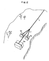
- a second embodiment of this invention relates to a method for installing conduits etc. on mountains using cables, comprising the steps of positioning at least one cable (“longitudinal cable”) on a mountainside along its slope, directly or indirectly mooring conduits, underground multi-purpose ducts, inlets ("conduits etc.”), through which water, fuel gases, electric wiring etc. pass, to the longitudinal cable, and connecting one end of the longitudinal cable to a base point that is fixed to the ridge or the mountain top.
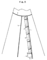
- a third embodiment of this invention relates to a method for installing conduits etc. on mountains using cables, comprising the steps of installing a cable for an anchor (“anchor cable”) around and near the top of a mountain that is generally conical, connecting at least one cable (“the longitudinal cable”) to the anchor cable, installing the longitudinal cable on the slope of the mountainside, and directly or indirectly mooring conduits, underground multi-purpose ducts, inlets (“conduits etc.”), through which water, fuel gases, electric wiring, etc. pass, to the longitudinal cable.
- Two or more longitudinal cables can be used. Also, at least one cable (“the lateral cable”) can be used to connect the two or more longitudinal cables.
- conduits etc. may be directly moored by the two or more longitudinal cables and the at least one lateral cable. Also, the conduits etc. may be indirectly moored to those cables by, for example, a mooring cable.
- the vertical cable may branch.
- conduits etc. may be used as a heavy object to act as an anchor.
- the anchor function that is needed to fix the conduits etc. is achieved by connecting one of the longitudinal cables, which crosses over the ridge of the mountain to be longitudinally positioned on both mountainsides, to the conduits etc., and by connecting the other to the heavy object that acts as an anchor so that the conduits etc. and the heavy object that acts an anchor may be arranged like a kayak.
- This method allows the strength of the anchor to resist both the force that causes the conduits etc. to move and the tensile force working against the cables.
- the strength of the anchor increases as the height of the mountain increases (or the length of the cables or the friction between the cable and the ground of the mountainside) and the weight of the heavy object (or an anchor) that is connected to the cable increases.
- a similar strength for the anchor can be achieved.
- the strength of the anchor of the second embodiment of this invention tends to be less than that of the first embodiment. Thus, when there is no need to use the relatively great strength of an anchor, the second embodiment is used.
- the third embodiment can be used to achieve a relatively great strength for the anchor.
- a shock such as an earthquake
- a fourth embodiment of this invention relates to a method for installing conduits etc. on a mountain using cables, comprising the steps of making at least one cable pass over the ridge of the mountain, installing said at least one cable on a mountainside and another mountainside opposite it ("opposite mountainside") that is bounded by the ridge of the mountain from that mountainside by passing the cable over the ridge, positioning the cable along both mountainsides, directly or indirectly mooring a base plate or a frame member to which right and left side plates are attached (“base etc.”) to the longitudinal cable that is positioned on one of the mountainsides, positioning on the base etc. conduits, underground multi-purpose ducts, or inlets (“conduits etc.”), through which water, fuel gases, electric wiring etc. pass, fixing the conduits etc. to the base or the side plates, and connecting the longitudinal cable that is installed on the opposite mountainside to a heavy object or a base point fixed to the mountain that acts as an anchor.
- a fifth embodiment of this invention relates to a method for installing conduits etc. on mountains using cables, comprising the steps of positioning at least one cable (“longitudinal cable”) on a mountainside along its slope, directly or indirectly mooring a base plate or a frame member, to which right and left side plates are attached (“base etc.”), to the longitudinal cable, positioning on the base etc. conduits, underground multi-purpose ducts, or inlets ("conduits etc.”), through which water, fuel gases, electric wiring etc. pass, fixing the conduits etc. to the base or the side plates, and connecting one end of the longitudinal cable to a base point that is fixed to the ridge or the mountain top.
- a sixth embodiment of this invention relates to a method for installing conduits etc. on mountains using cables, comprising the steps of installing a cable for an anchor ("anchor cable”) around and near the top of a mountain that is generally conical, connecting at least one cable (“longitudinal cable”) to the anchor cable, installing the longitudinal cable on a slope of a mountain, directly or indirectly mooring a base plate or a frame member, to which right and left side plates are attached (“base etc.”), to the longitudinal cable, positioning on the base etc. conduits, underground multi-purpose ducts, or inlets (“conduits etc.”), through which water, fuel gases, electric wiring etc. pass, and fixing the conduits etc. to the base or the side plates.
- the base etc. may be moored by one longitudinal cable. However, preferably one base etc. is moored to two or more longitudinal cables, especially to two longitudinal cables.
- Mooring the base etc. to the longitudinal cable indirectly can be achieved by, for example, using a cable that is positioned at an angle ("lateral cable") relative to the longitudinal direction of the longitudinal cable (e.g., 90 degrees), connecting the base, etc. to the lateral cable, and connecting the lateral cable to the longitudinal cable, thereby mooring the base etc. to the longitudinal cable.
- lateral cable an angle relative to the longitudinal direction of the longitudinal cable (e.g., 90 degrees)
- Two or more longitudinal cables can be used. Also, at least one additional lateral cable can be used to connect the longitudinal cables.
- the longitudinal cable may branch.
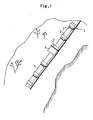
- one cable 1 crosses over a ridge of a mountain and hangs down both mountainsides.
- conduits 3 and inlets 4 are moored to mooring cables 2 that are connected to the longitudinal cable 1.
- a heavy object 5a which acts an anchor, is moored by the longitudinal cable 1.
- other heavy objects 5b are moored to the longitudinal cable 1 by the mooring cables 2. The tensile stresses on the cable are balanced on both mountainsides.
- the conduits 3 and the inlets 4 can be stably held at fixed positions.
- Fig. 3 shows another embodiment of this invention, where the diameter of the conduit is relatively great.
- three longitudinal cables 1 are positioned in parallel along the mountainside.
- Lateral cables 6 are connected between the longitudinal cables 1.
- the conduits 3 and inlets 4 are moored by the lateral cables 6.
- the heavy objects may be moored by the longitudinal cable 1 on the rear mountainside.
- the longitudinal cable 1 may be connected to a certain base point that is fixed on the top or a ridge of a mountain, or the backside of a mountain.
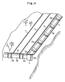
- Fig. 4 shows still another embodiment according to this invention.
- the conduits are positioned along topographic features of the mountainside so that they are not arranged straight from the top of the mountain toward its bottom, but change direction. That is, the conduits 3a are arranged from the top of the mountain toward its bottom, and are moored by the mooring cables 2a.
- the mooring cables 2a are connected to the longitudinal cable 1.
- the lowest end of a series of the conduits 3a is connected to the inlet 4.
- the series of the conduits changes course. That is, a series of conduits 3b is laterally positioned and connected to the inlet 4.
- the conduits 3b are moored by the mooring cables 2b.
- the mooring cables 2b are connected to a lateral cable 6.
- the lateral cable 6 extends across the longitudinal cables 1 and is connected to them.
- heavy objects may be moored by the longitudinal cables 1 to the rear mountainside.
- the longitudinal cable 1 may be connected to a certain base point that is fixed on the top or ridge of a mountain, or the backside of a mountain.
- each longitudinal cable may comprise a basic part 1 and a branching part 1'. This construction allows the conduits 3b and the inlets 4 to be firmly moored.
- a cable 7 is wound around near the top of a mountain.
- the cable 7 is used as an anchor.
- the longitudinal cables 1 are connected to the cable 7.
- the longitudinal cables 1 are suspended along the mountainside.
- the conduits 3 and inlets 4 are moored by the mooring cables 2.
- the cables 2 are connected to the longitudinal cables 1.
- the conduits etc. according to this invention are used to indicate an inclusive concept that includes a water pipe, a sewage pipe, a gas pipe, and a pipe for electric wiring, an underground multi-purpose duct that accommodates them, and an inlet that is used to connect those pipes.
- the materials for those pipes are not limited.
- the conduits etc. When the conduits etc. are moored by the cables, they may be directed in any direction. For example, they can be arranged to be directed toward the top of a mountain. Also, like the conduits that are described in Fig. 4 at the lower position, they can be arranged perpendicularly to the top of a mountain (i.e. laterally). Also, besides the above direction, they can be directed in any other direction.
- the conduits etc. may be buried, if necessary. Also, to facilitate the mooring of the conduits etc. by the cables, the surfaces of the conduits etc. may be concave or convex, or both. Also, projections may be formed on those surfaces.
- a conduit (which is not limited to just one) that is positioned at one end of a series of a number of conduits that are connected to each other may be directly connected to conduits etc. arranged in a building, or indirectly connected to the building through branch ducts.
- a conduit (which is also not limited to just one) that is positioned at the other end may be directly connected to various facilities according to its purposes (alternatively, the series of the conduits may be made to extend from the facilities).
- the conduits etc. can be installed on the flat land in any way that is known by one skilled in the art.
- the cables can interlock with each other. Also, they can be connected to each other by known connectors.
- a block of concrete, a metal block, or a long wire basket filled with rocks can be used.
- a base points that are fixed on a mountain a big tree or a concrete building that is connected to the ground can be used.
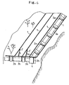
- two longitudinal cables 1, 1 cross over the ridge of a mountain and are longitudinally positioned on both mountainsides.
- a base 8 on which the conduits 3 are fixed is moored by longitudinal cables 1, 1'.
- a heavy object that acts as an anchor is moored by each longitudinal cable 1, 1'. The tensile stresses against the cable are balanced on both mountainsides.
- the base 8, on which the conduits 3 are fixed can be stably held at fixed positions.
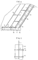
- Fig. 8 shows an embodiment according to this invention where bases 8a, 8b are not arranged to run straight from the top of the mountain toward its bottom, but are positioned along topographic features of the mountainside.
- the base 8a which is arranged from the top of the mountain toward its bottom, is moored by the two longitudinal cables 1, 1'.
- the lowest end of a series of the conduits 3a is connected to the inlet 4.
- the series of the conduits changes direction.
- the inlet 4 and the conduits 3b are fixed on the base 8b.
- the base 8b is moored by the longitudinal cables 1, 1, 1, 1 that are connected to the lateral cables 6.
- the lateral cables 6 are connected to the base 8b.
- each longitudinal cable 1 may be connected to a certain base point that is fixed on the top or ridge of a mountain, or the backside of a mountain.
- each longitudinal cable 1 may be comprised of a basic part 1 and a branching part 1', as in Fig. 6.
- the conduits etc. 3 may be moored by using the base 8. That is, the base 8, on which the conduits 3 are fixed, may be moored by the longitudinal cables 1.
- the longitudinal cables 1 are connected to the anchor cable 7 that is wound around the top of a mountain.
- FIG. 9 is a schematic view to show the back side of the base 8 (which is not a surface on which the conduits etc. are positioned and fixed).
- a plurality of the lateral cables are connected and fixed to the sides of the base 8.
- a single longitudinal cable 1 is connected to the plurality of the lateral cables.
- the heavy objects that act as anchors and that are used by the embodiments in Figs. 1-4 and 6 are the same.
- the base etc., on which the conduits etc. are fixed can be used as anchors.
- the conduits etc. that are not fixed on the base, but which are moored by cables, can be used as anchors.
- the base points that are fixed on a mountain, a big tree or a concrete building that is connected to the ground can be used.
- the cables can interlock with each other. Also, they can be connected to each other by known connectors 9. Also, the cables may be connected to the base or the frame (that is constructed by forming a right plate on one side and a left plate on the other side) by using a known joiner 10.
- the materials for the base or the frame are not limited to a specific material.
- concrete and steel can be used.
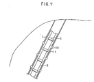
- the method for fixing the conduits etc. to the base etc. is not limited to a specific method. Examples are: 1) a method for driving joining parts 11 that are made of steel and shaped like a semicircle or " ⁇ " around the conduits into the base (in Fig. 7), 2), a method for forming projections on the surface of the base at certain intervals to fit a relatively large part of the conduit to them, and 3) a method for forming holes on both the conduits and the bases etc. so that they are coupled by a bolt and nut.
- the conduits etc. can be fixed on either the basic part or the side plate part of it.
Landscapes
- Engineering & Computer Science (AREA)
- General Engineering & Computer Science (AREA)
- Mechanical Engineering (AREA)
- Health & Medical Sciences (AREA)
- Life Sciences & Earth Sciences (AREA)
- Hydrology & Water Resources (AREA)
- Public Health (AREA)
- Water Supply & Treatment (AREA)
- Laying Of Electric Cables Or Lines Outside (AREA)
- Cable Accessories (AREA)
- Communication Cables (AREA)
- Insulated Conductors (AREA)
- Electric Cable Installation (AREA)
- Near-Field Transmission Systems (AREA)
- Rigid Pipes And Flexible Pipes (AREA)
- Supports For Pipes And Cables (AREA)
- Devices Affording Protection Of Roads Or Walls For Sound Insulation (AREA)
Applications Claiming Priority (3)
| Application Number | Priority Date | Filing Date | Title |
|---|---|---|---|
| PCT/JP1999/000362 WO2000044996A1 (fr) | 1999-01-28 | 1999-01-28 | Procede permettant l'installation d'une conduite ou d'un tube similaire sur une montagne au moyen d'un cable |
| WOPCT/JP99/00362 | 1999-01-28 | ||
| PCT/JP2000/000458 WO2000044997A1 (fr) | 1999-01-28 | 2000-01-28 | Procede d'installation d'un conduit ou analogues sur une surface de montagne au moyen d'un cable en acier |
Publications (3)
| Publication Number | Publication Date |
|---|---|
| EP1069251A1 true EP1069251A1 (fr) | 2001-01-17 |
| EP1069251A4 EP1069251A4 (fr) | 2004-06-16 |
| EP1069251B1 EP1069251B1 (fr) | 2006-04-12 |
Family
ID=14234809
Family Applications (1)
| Application Number | Title | Priority Date | Filing Date |
|---|---|---|---|
| EP00901967A Expired - Lifetime EP1069251B1 (fr) | 1999-01-28 | 2000-01-28 | Procede d'installation d'un conduit ou analogues sur une surface de montagne au moyen d'un cable en acier |
Country Status (13)
| Country | Link |
|---|---|
| US (2) | US6588984B1 (fr) |
| EP (1) | EP1069251B1 (fr) |
| KR (1) | KR100449935B1 (fr) |
| CN (1) | CN1136367C (fr) |
| AT (1) | ATE323256T1 (fr) |
| AU (2) | AU2184399A (fr) |
| BR (1) | BR0004492A (fr) |
| CA (1) | CA2326123C (fr) |
| DE (1) | DE60027228T2 (fr) |
| EA (1) | EA002046B1 (fr) |
| ID (1) | ID26288A (fr) |
| NO (1) | NO20004836L (fr) |
| WO (2) | WO2000044996A1 (fr) |
Cited By (2)
| Publication number | Priority date | Publication date | Assignee | Title |
|---|---|---|---|---|
| CN101806377A (zh) * | 2010-04-29 | 2010-08-18 | 中国石油化工集团公司 | 中大型陡崖管道安装施工方法 |
| CN106594392A (zh) * | 2017-01-13 | 2017-04-26 | 中国电力工程顾问集团西南电力设计院有限公司 | 一种大坡度热力管道支架管部结构及制作方法 |
Families Citing this family (10)
| Publication number | Priority date | Publication date | Assignee | Title |
|---|---|---|---|---|
| AU2184399A (en) * | 1999-01-28 | 2000-08-18 | Tomio Fukui | Method of installing conduit or the like on mountain using cable |
| US6969215B2 (en) * | 2004-03-11 | 2005-11-29 | Duncan Kenneth R | Method and apparatus for laying pipe on an incline |
| KR100672237B1 (ko) * | 2006-10-14 | 2007-01-24 | 주식회사 삼안 | 경사면 하수관 결속구조 |
| KR100862166B1 (ko) * | 2008-03-28 | 2008-10-10 | 한라산업개발 주식회사 | 개착식 하상여과공법을 이용한 집수시스템 |
| KR100862167B1 (ko) * | 2008-03-28 | 2008-10-10 | 한라산업개발 주식회사 | 개착식 하상여과공법을 이용한 간접취수원 확보 시스템 |
| RU2477410C1 (ru) * | 2011-11-10 | 2013-03-10 | Федеральное государственное бюджетное образовательное учреждение высшего профессионального образования "Санкт-Петербургский государственный горный университет" | Способ прокладки трубопровода в скальных породах гористого участка |
| JP6335828B2 (ja) * | 2015-04-03 | 2018-05-30 | 株式会社栗本鐵工所 | さや管推進工法 |
| CN105003738B (zh) * | 2015-07-02 | 2017-05-17 | 山西宏厦建筑工程有限公司 | 山区复杂地形运用索道安装大管径管道施工工法 |
| CN106151682B (zh) * | 2016-07-15 | 2018-01-30 | 中国葛洲坝集团机电建设有限公司 | 高边坡大型压力钢管安装下放装置及压力钢管安装方法 |
| CN106869035B (zh) * | 2017-03-24 | 2018-10-09 | 中石化江苏油建工程有限公司 | 跨越峡谷管道桥的安装方法 |
Family Cites Families (20)
| Publication number | Priority date | Publication date | Assignee | Title |
|---|---|---|---|---|
| US2034928A (en) * | 1934-03-23 | 1936-03-24 | Bell Telephone Labor Inc | Cable shield |
| US2091265A (en) * | 1936-01-18 | 1937-08-31 | Du Pont | Flexible noncollapsible tubing |
| US2962599A (en) * | 1957-09-09 | 1960-11-29 | Frank Z Pirkey | Apparatus for developing and accumulating hydroelectric energy |
| US3248884A (en) * | 1963-07-15 | 1966-05-03 | Richard B Bender | Pipeline ditch breaker |
| US3657786A (en) * | 1970-03-11 | 1972-04-25 | George C Wiswell Jr | Laying of subaqueous pipe |
| US3810364A (en) * | 1971-12-30 | 1974-05-14 | T Johnson | Ground anchor |
| US3853182A (en) * | 1973-11-26 | 1974-12-10 | Continental Oil Co | Launch tube for a long hole drilling apparatus |
| JPS5326984A (en) * | 1976-08-25 | 1978-03-13 | Hitachi Cable Ltd | Buried cable laid in slope |
| US4073157A (en) * | 1976-10-26 | 1978-02-14 | Piccal Subsea Limited | Offshore method |
| JPS576176A (en) * | 1980-06-06 | 1982-01-13 | Sekisui Chemical Co Ltd | Floating-up preventing method of buried pipe |
| US4454951A (en) * | 1982-06-16 | 1984-06-19 | Champion International Corporation | Remote controlled slack pulling log skidding carriage |
| JPS6037318A (ja) * | 1983-08-08 | 1985-02-26 | Mitsubishi Heavy Ind Ltd | 水圧鉄管の据付方法 |
| US4735327A (en) * | 1986-05-30 | 1988-04-05 | The United States Of America As Represented By The Secretary Of Agriculture | Radio controlled downhill skyline logging carriage and system |
| US4687109A (en) * | 1986-07-03 | 1987-08-18 | Davis Glenn T | Radio controlled electric slack puller, brake and battery recharging system |
| US4842314A (en) * | 1988-03-24 | 1989-06-27 | Bellow Don W | Pipe lift cap assembly |
| JPH08291880A (ja) * | 1995-04-21 | 1996-11-05 | Hiroshi Kitagawa | 埋設管体の位置規制具 |
| DE19521289A1 (de) * | 1995-06-10 | 1996-12-12 | Thorsten Boecher | Energiegewinnungs- und Bewässerungssystem |
| US6145679A (en) * | 1996-02-07 | 2000-11-14 | Walters; Victor | Shiftable tail-block logging skyline |
| EA000655B1 (ru) * | 1996-10-18 | 1999-12-29 | Томио Фукуи | Способы строительства для предотвращения эрозии грунта и совершенствования потоков или строительства подпорных стенок, а также способы строительства для предотвращения оползней в горах |
| AU2184399A (en) * | 1999-01-28 | 2000-08-18 | Tomio Fukui | Method of installing conduit or the like on mountain using cable |
-
1999
- 1999-01-28 AU AU21843/99A patent/AU2184399A/en not_active Abandoned
- 1999-01-28 WO PCT/JP1999/000362 patent/WO2000044996A1/fr not_active Ceased
-
2000
- 2000-01-28 CN CNB008000905A patent/CN1136367C/zh not_active Expired - Fee Related
- 2000-01-28 EA EA200001003A patent/EA002046B1/ru not_active IP Right Cessation
- 2000-01-28 BR BR0004492-0A patent/BR0004492A/pt not_active IP Right Cessation
- 2000-01-28 US US09/647,446 patent/US6588984B1/en not_active Expired - Fee Related
- 2000-01-28 CA CA002326123A patent/CA2326123C/fr not_active Expired - Fee Related
- 2000-01-28 AT AT00901967T patent/ATE323256T1/de not_active IP Right Cessation
- 2000-01-28 EP EP00901967A patent/EP1069251B1/fr not_active Expired - Lifetime
- 2000-01-28 ID IDW20001929A patent/ID26288A/id unknown
- 2000-01-28 AU AU23209/00A patent/AU744021B2/en not_active Ceased
- 2000-01-28 DE DE60027228T patent/DE60027228T2/de not_active Expired - Fee Related
- 2000-01-28 KR KR10-2000-7010772A patent/KR100449935B1/ko not_active Expired - Fee Related
- 2000-01-28 WO PCT/JP2000/000458 patent/WO2000044997A1/fr not_active Ceased
- 2000-09-26 NO NO20004836A patent/NO20004836L/no not_active Application Discontinuation
-
2003
- 2003-05-19 US US10/440,748 patent/US6742964B2/en not_active Expired - Fee Related
Cited By (2)
| Publication number | Priority date | Publication date | Assignee | Title |
|---|---|---|---|---|
| CN101806377A (zh) * | 2010-04-29 | 2010-08-18 | 中国石油化工集团公司 | 中大型陡崖管道安装施工方法 |
| CN106594392A (zh) * | 2017-01-13 | 2017-04-26 | 中国电力工程顾问集团西南电力设计院有限公司 | 一种大坡度热力管道支架管部结构及制作方法 |
Also Published As
| Publication number | Publication date |
|---|---|
| WO2000044996A1 (fr) | 2000-08-03 |
| US6742964B2 (en) | 2004-06-01 |
| EP1069251B1 (fr) | 2006-04-12 |
| CN1293730A (zh) | 2001-05-02 |
| HK1036307A1 (en) | 2001-12-28 |
| NO20004836D0 (no) | 2000-09-26 |
| AU2320900A (en) | 2000-08-18 |
| AU744021B2 (en) | 2002-02-14 |
| DE60027228D1 (de) | 2006-05-24 |
| AU2184399A (en) | 2000-08-18 |
| US6588984B1 (en) | 2003-07-08 |
| EA200001003A1 (ru) | 2001-02-26 |
| ATE323256T1 (de) | 2006-04-15 |
| CN1136367C (zh) | 2004-01-28 |
| CA2326123C (fr) | 2005-01-11 |
| KR20010042242A (ko) | 2001-05-25 |
| EP1069251A4 (fr) | 2004-06-16 |
| ID26288A (id) | 2000-12-14 |
| WO2000044997A1 (fr) | 2000-08-03 |
| BR0004492A (pt) | 2000-12-19 |
| CA2326123A1 (fr) | 2000-08-03 |
| EA002046B1 (ru) | 2001-12-24 |
| US20030194276A1 (en) | 2003-10-16 |
| DE60027228T2 (de) | 2007-03-29 |
| NO20004836L (no) | 2000-09-26 |
| KR100449935B1 (ko) | 2004-09-24 |
Similar Documents
| Publication | Publication Date | Title |
|---|---|---|
| US6742964B2 (en) | Method for installing conduit or the like on mountainside | |
| US6695528B2 (en) | Method for constructing structures useful as scaffolds on slopes | |
| CN111535159B (zh) | 盖板式索道桥桥台 | |
| NZ507004A (en) | Method of installing conduit or the like on mountainside using steel cable | |
| KR102206864B1 (ko) | 지하시설물용 매설 구조물 | |
| EP0051091B1 (fr) | Arrangement de colonnes montantes pour systèmes de production | |
| MXPA00009453A (en) | Method of installing conduit or the like on mountain surface using steel cable | |
| CN211605429U (zh) | 一种长距离管廊接地扁钢连接结构 | |
| CN217174846U (zh) | 一种悬索形和斜拉形复合柔性边坡锚固结构 | |
| CN217176372U (zh) | 综合管廊内的防火门预固定组件及综合管廊 | |
| JP7073185B2 (ja) | 壁高欄埋設管路用作業空間の構造、構築方法及び構築に用いる型枠 | |
| US20220220692A1 (en) | Mechanically stabilized earth (mse) retaining wall employing round rods with spaced pullout inhibiting structures | |
| KR100883271B1 (ko) | 지중 배선 관로 | |
| CN220364848U (zh) | 抗推力人行拱桥 | |
| CN113174979A (zh) | 一种悬索形和斜拉形复合柔性边坡锚固结构 | |
| CN219994602U (zh) | 一种基坑内原有刚性管道悬吊结构 | |
| CN218522678U (zh) | 反力结构和箱涵推进系统 | |
| HK1036307B (en) | Method of installing conduit or the like on mountain surface using steel cable | |
| JPH11256877A (ja) | 仮設用長尺ポール部材の取付構造 | |
| JPWO2000044997A1 (ja) | 鋼索を利用する山地における導管等の設置方法 | |
| CN115467670A (zh) | 箱涵推进结构和隧道开挖系统 | |
| JPH0461564B2 (fr) | ||
| JPH0965532A (ja) | 立金物取付用支持金具 | |
| JPS5817916A (ja) | 地盤補強体 | |
| JPH0771652A (ja) | 地下共同管路 |
Legal Events
| Date | Code | Title | Description |
|---|---|---|---|
| PUAI | Public reference made under article 153(3) epc to a published international application that has entered the european phase |
Free format text: ORIGINAL CODE: 0009012 |
|
| 17P | Request for examination filed |
Effective date: 20001027 |
|
| AK | Designated contracting states |
Kind code of ref document: A1 Designated state(s): AT BE CH CY DE DK ES FI FR GB GR IE IT LI LU MC NL PT SE |
|
| AX | Request for extension of the european patent |
Free format text: AL PAYMENT 20001027;LT PAYMENT 20001027;LV PAYMENT 20001027;MK PAYMENT 20001027;RO PAYMENT 20001027;SI PAYMENT 20001027 |
|
| A4 | Supplementary search report drawn up and despatched |
Effective date: 20040507 |
|
| RIC1 | Information provided on ipc code assigned before grant |
Ipc: 7F 16L 1/00 A Ipc: 7F 16L 1/024 B |
|
| 17Q | First examination report despatched |
Effective date: 20050412 |
|
| GRAP | Despatch of communication of intention to grant a patent |
Free format text: ORIGINAL CODE: EPIDOSNIGR1 |
|
| GRAS | Grant fee paid |
Free format text: ORIGINAL CODE: EPIDOSNIGR3 |
|
| GRAA | (expected) grant |
Free format text: ORIGINAL CODE: 0009210 |
|
| AK | Designated contracting states |
Kind code of ref document: B1 Designated state(s): AT BE CH CY DE DK ES FI FR GB GR IE IT LI LU MC NL PT SE |
|
| AX | Request for extension of the european patent |
Extension state: AL LT LV MK RO SI |
|
| PG25 | Lapsed in a contracting state [announced via postgrant information from national office to epo] |
Ref country code: FI Free format text: LAPSE BECAUSE OF FAILURE TO SUBMIT A TRANSLATION OF THE DESCRIPTION OR TO PAY THE FEE WITHIN THE PRESCRIBED TIME-LIMIT Effective date: 20060412 Ref country code: IT Free format text: LAPSE BECAUSE OF FAILURE TO SUBMIT A TRANSLATION OF THE DESCRIPTION OR TO PAY THE FEE WITHIN THE PRESCRIBED TIME-LIMIT;WARNING: LAPSES OF ITALIAN PATENTS WITH EFFECTIVE DATE BEFORE 2007 MAY HAVE OCCURRED AT ANY TIME BEFORE 2007. THE CORRECT EFFECTIVE DATE MAY BE DIFFERENT FROM THE ONE RECORDED. Effective date: 20060412 Ref country code: LI Free format text: LAPSE BECAUSE OF FAILURE TO SUBMIT A TRANSLATION OF THE DESCRIPTION OR TO PAY THE FEE WITHIN THE PRESCRIBED TIME-LIMIT Effective date: 20060412 Ref country code: BE Free format text: LAPSE BECAUSE OF FAILURE TO SUBMIT A TRANSLATION OF THE DESCRIPTION OR TO PAY THE FEE WITHIN THE PRESCRIBED TIME-LIMIT Effective date: 20060412 Ref country code: CH Free format text: LAPSE BECAUSE OF FAILURE TO SUBMIT A TRANSLATION OF THE DESCRIPTION OR TO PAY THE FEE WITHIN THE PRESCRIBED TIME-LIMIT Effective date: 20060412 Ref country code: NL Free format text: LAPSE BECAUSE OF FAILURE TO SUBMIT A TRANSLATION OF THE DESCRIPTION OR TO PAY THE FEE WITHIN THE PRESCRIBED TIME-LIMIT Effective date: 20060412 Ref country code: AT Free format text: LAPSE BECAUSE OF FAILURE TO SUBMIT A TRANSLATION OF THE DESCRIPTION OR TO PAY THE FEE WITHIN THE PRESCRIBED TIME-LIMIT Effective date: 20060412 |
|
| REG | Reference to a national code |
Ref country code: GB Ref legal event code: FG4D |
|
| REG | Reference to a national code |
Ref country code: CH Ref legal event code: EP |
|
| REF | Corresponds to: |
Ref document number: 60027228 Country of ref document: DE Date of ref document: 20060524 Kind code of ref document: P |
|
| REG | Reference to a national code |
Ref country code: IE Ref legal event code: FG4D |
|
| PG25 | Lapsed in a contracting state [announced via postgrant information from national office to epo] |
Ref country code: DK Free format text: LAPSE BECAUSE OF FAILURE TO SUBMIT A TRANSLATION OF THE DESCRIPTION OR TO PAY THE FEE WITHIN THE PRESCRIBED TIME-LIMIT Effective date: 20060712 Ref country code: SE Free format text: LAPSE BECAUSE OF FAILURE TO SUBMIT A TRANSLATION OF THE DESCRIPTION OR TO PAY THE FEE WITHIN THE PRESCRIBED TIME-LIMIT Effective date: 20060712 |
|
| PG25 | Lapsed in a contracting state [announced via postgrant information from national office to epo] |
Ref country code: ES Free format text: LAPSE BECAUSE OF FAILURE TO SUBMIT A TRANSLATION OF THE DESCRIPTION OR TO PAY THE FEE WITHIN THE PRESCRIBED TIME-LIMIT Effective date: 20060723 |
|
| PG25 | Lapsed in a contracting state [announced via postgrant information from national office to epo] |
Ref country code: PT Free format text: LAPSE BECAUSE OF FAILURE TO SUBMIT A TRANSLATION OF THE DESCRIPTION OR TO PAY THE FEE WITHIN THE PRESCRIBED TIME-LIMIT Effective date: 20060912 |
|
| LTIE | Lt: invalidation of european patent or patent extension |
Effective date: 20060412 |
|
| NLV1 | Nl: lapsed or annulled due to failure to fulfill the requirements of art. 29p and 29m of the patents act | ||
| REG | Reference to a national code |
Ref country code: CH Ref legal event code: PL |
|
| ET | Fr: translation filed | ||
| PG25 | Lapsed in a contracting state [announced via postgrant information from national office to epo] |
Ref country code: MC Free format text: LAPSE BECAUSE OF NON-PAYMENT OF DUE FEES Effective date: 20070131 |
|
| PLBE | No opposition filed within time limit |
Free format text: ORIGINAL CODE: 0009261 |
|
| STAA | Information on the status of an ep patent application or granted ep patent |
Free format text: STATUS: NO OPPOSITION FILED WITHIN TIME LIMIT |
|
| 26N | No opposition filed |
Effective date: 20070115 |
|
| PG25 | Lapsed in a contracting state [announced via postgrant information from national office to epo] |
Ref country code: IE Free format text: LAPSE BECAUSE OF NON-PAYMENT OF DUE FEES Effective date: 20070129 |
|
| PG25 | Lapsed in a contracting state [announced via postgrant information from national office to epo] |
Ref country code: GR Free format text: LAPSE BECAUSE OF FAILURE TO SUBMIT A TRANSLATION OF THE DESCRIPTION OR TO PAY THE FEE WITHIN THE PRESCRIBED TIME-LIMIT Effective date: 20060713 |
|
| PGFP | Annual fee paid to national office [announced via postgrant information from national office to epo] |
Ref country code: DE Payment date: 20090127 Year of fee payment: 10 |
|
| PGFP | Annual fee paid to national office [announced via postgrant information from national office to epo] |
Ref country code: GB Payment date: 20090119 Year of fee payment: 10 |
|
| PG25 | Lapsed in a contracting state [announced via postgrant information from national office to epo] |
Ref country code: CY Free format text: LAPSE BECAUSE OF FAILURE TO SUBMIT A TRANSLATION OF THE DESCRIPTION OR TO PAY THE FEE WITHIN THE PRESCRIBED TIME-LIMIT Effective date: 20060412 Ref country code: LU Free format text: LAPSE BECAUSE OF NON-PAYMENT OF DUE FEES Effective date: 20070128 |
|
| PGFP | Annual fee paid to national office [announced via postgrant information from national office to epo] |
Ref country code: IT Payment date: 20090130 Year of fee payment: 10 |
|
| PGFP | Annual fee paid to national office [announced via postgrant information from national office to epo] |
Ref country code: FR Payment date: 20090112 Year of fee payment: 10 |
|
| GBPC | Gb: european patent ceased through non-payment of renewal fee |
Effective date: 20100128 |
|
| REG | Reference to a national code |
Ref country code: FR Ref legal event code: ST Effective date: 20100930 |
|
| PG25 | Lapsed in a contracting state [announced via postgrant information from national office to epo] |
Ref country code: FR Free format text: LAPSE BECAUSE OF NON-PAYMENT OF DUE FEES Effective date: 20100201 |
|
| PG25 | Lapsed in a contracting state [announced via postgrant information from national office to epo] |
Ref country code: DE Free format text: LAPSE BECAUSE OF NON-PAYMENT OF DUE FEES Effective date: 20100803 |
|
| PG25 | Lapsed in a contracting state [announced via postgrant information from national office to epo] |
Ref country code: GB Free format text: LAPSE BECAUSE OF NON-PAYMENT OF DUE FEES Effective date: 20100128 |
|
| PG25 | Lapsed in a contracting state [announced via postgrant information from national office to epo] |
Ref country code: IT Free format text: LAPSE BECAUSE OF NON-PAYMENT OF DUE FEES Effective date: 20100128 |