EP1069234B1 - Method and device for removing impurities from a hydrocyclone - Google Patents
Method and device for removing impurities from a hydrocyclone Download PDFInfo
- Publication number
- EP1069234B1 EP1069234B1 EP00112006A EP00112006A EP1069234B1 EP 1069234 B1 EP1069234 B1 EP 1069234B1 EP 00112006 A EP00112006 A EP 00112006A EP 00112006 A EP00112006 A EP 00112006A EP 1069234 B1 EP1069234 B1 EP 1069234B1
- Authority
- EP
- European Patent Office
- Prior art keywords
- hydrocyclone
- dilution liquid
- added
- suspension
- addition point
- Prior art date
- Legal status (The legal status is an assumption and is not a legal conclusion. Google has not performed a legal analysis and makes no representation as to the accuracy of the status listed.)
- Expired - Lifetime
Links
Images


Classifications
-
- D—TEXTILES; PAPER
- D21—PAPER-MAKING; PRODUCTION OF CELLULOSE
- D21D—TREATMENT OF THE MATERIALS BEFORE PASSING TO THE PAPER-MAKING MACHINE
- D21D5/00—Purification of the pulp suspension by mechanical means; Apparatus therefor
- D21D5/18—Purification of the pulp suspension by mechanical means; Apparatus therefor with the aid of centrifugal force
- D21D5/24—Purification of the pulp suspension by mechanical means; Apparatus therefor with the aid of centrifugal force in cyclones
-
- B—PERFORMING OPERATIONS; TRANSPORTING
- B04—CENTRIFUGAL APPARATUS OR MACHINES FOR CARRYING-OUT PHYSICAL OR CHEMICAL PROCESSES
- B04C—APPARATUS USING FREE VORTEX FLOW, e.g. CYCLONES
- B04C11/00—Accessories, e.g. safety or control devices, not otherwise provided for, e.g. regulators, valves in inlet or overflow ducting
-
- B—PERFORMING OPERATIONS; TRANSPORTING
- B04—CENTRIFUGAL APPARATUS OR MACHINES FOR CARRYING-OUT PHYSICAL OR CHEMICAL PROCESSES
- B04C—APPARATUS USING FREE VORTEX FLOW, e.g. CYCLONES
- B04C5/00—Apparatus in which the axial direction of the vortex is reversed
- B04C5/14—Construction of the underflow ducting; Apex constructions; Discharge arrangements ; discharge through sidewall provided with a few slits or perforations
- B04C5/18—Construction of the underflow ducting; Apex constructions; Discharge arrangements ; discharge through sidewall provided with a few slits or perforations with auxiliary fluid assisting discharge
Definitions
- the invention relates to a method according to the preamble of claim 1.
- hydrocyclones are well suited to removing heavy parts by centrifugal forces or concentrate light parts in fiber suspensions and by using one to lead the intended discharge opening out of the hydrocyclone.
- the operational safety especially the freedom from clogging of such hydrocyclones particularly important. Blockages can occur if the contaminants, e.g. in the area of the discharge opening provided for them, so collect and concentrate that there is a blockage. In many cases, a A compromise can be found between operational safety, i.e.
- a known way to To reduce the risk of constipation on heavy-duty hydrocyclones is that a dilution liquid is supplied.
- a water supply line opens into the Edge area of the hydrocyclone e.g. through slots in the circumferential direction in the Cyclone wall.
- the dilution liquid then whirls up the outer layers and must penetrate the heavy dirt already concentrated in it, resulting in a Backwashing heavy parts in the accept stream can result.
- the invention is based on the object of a method for applying To create contaminants from hydrocyclones, with which both a reliable Removal of the contaminants is possible, as well as a good separation effect.
- the dilution liquid is therefore not introduced into the Edge of the hydrocyclone, where blockage is expected, but in the middle, with axial Direction, and thus mainly in the core flow.
- the dilution liquid With a sufficiently large one Inflow velocity the dilution liquid reaches the conical area of the separating room and mixes through the effect of the ones prevailing there Gradually shear flow with the surrounding pulp suspension.
- the kind of Dilution leads to a gentle backwashing of the fibers in the accepted fabric without that the same thing happens with already concentrated heavy parts, since these are on the wall and are not affected by the dilution water addition. Without the measures according to the invention, some of those that have already been concentrated would be concentrated Heavy parts whirled up and get into the middle of the hydrocyclone. From there then discharged with the accepted material.
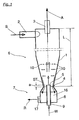
- FIG. 1 shows a hydrocyclone according to the invention, roughly schematically an inlet 2 for the paper fiber-containing suspension S and an accept material outlet 3 for the cleaned suspension, i.e. the accepted substance A.
- the suspension S to be cleaned becomes set in rotation and enters the separating part 6 with a separating cone 1, in which usually increases the speed of rotation again. This will the contained heavy parts ST concentrated on the inner wall of the separating cone 1 and go down into the reject discharge device 17.
- the addition point 5 intended for this has the narrowest Position 4 of the separating cone 1 is the distance a, which is preferably in axial Seen direction, is at most a few millimeters.
- this can Distance a up to 30% of the length L of the hydrocyclone.
- Another sensible one The requirement is that the axial distance to the inlet 2 be kept as large as possible e.g. at least 70% of the length L of the hydrocyclone.
- the heavy parts ST fall, after they have passed the narrowest point 4 of the separating cone 1, into the Discharge chamber 8 from which it, e.g. via a discharge device 17, as reject R be removed.
- This discharge can take place continuously or intermittently.
- the dilution liquid W is replaced by a simple one vertical inlet pipe 9 is added, which is an axial and at the addition point 5 against the discharge direction of the contaminants ST has an opening.
- Circumferential component Vu (see FIG. 5) is so low compared to the axial speed Vax to hold that the angle ⁇ between the resultant of the two vectors and the Axis does not exceed 30 °. Overall, with this type of Add dilution water to a much larger volume distributed and is therefore less harmful to the separation effect.
- the liquid W is particularly advantageously at a certain axial position in the Hydrocyclone entered. Then there is only one opening at the addition point 5. It may be possible to adjust their position in the axial direction.
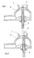
- FIG. 2 shows a variant for carrying out the method Dilution liquid W via a curved inlet pipe 9 directly in the middle of the entered reject tube 11 below the separating cone 1. It is here the addition point 5 selected so that it is below the narrowest point 4, what but not necessarily so.
- FIG. 3 shows a further possibility for carrying out the method.
- the Dilution liquid W first placed in a flow insert 16 ', in the Inside there is a central displacement body 12, so that an annular Flow cross section arises.
- the ring-shaped jet easily penetrates the one above part of the separating cone. It is also indicated here by arrows, like that Heavy parts ST slide down into the discharge chamber 8 near the wall. she can do this without going through the flow of the dilution liquid into the core flow of the Hydrocyclones to be flushed.
- FIG. 4 shows an axial inflow of the Dilution liquid W through the central inlet pipe 9. It opens inside the Flow insert 16 "via an injector 13 into a central tube 14. This allows Parts of the suspension are sucked out of the hydrocyclone and in the middle again be added, which serves the stable operation and the fiber loss minimized.
- FIG. 6darsch A hydrocyclone similar to that in FIG. 1 is shown in a perspective view in FIG. 6darsch. More constructive details are visible, but also these Drawing is still greatly simplified.
- FIG. 7 essentially shows the lower part of FIG. 6 in an enlarged form. you thus recognizes more easily that the inlet pipe 9 is screwed in exactly in the middle and in one circular opening opens here above the narrowest point 4. It's easy too mount and can be adjusted axially. With the help of the axial adjustment is one better adjustment of the hydrocyclone to the existing conditions possible.
- the discharge chamber 8 of FIG. 8 has a slightly eccentrically inserted one Inlet pipe 9, but this remains in the radially inner region of the hydrocyclone.
- the outlet cross-section of the inlet pipe 9 keeps one from the wall of the hydrocyclone Distance b a, which is at least 10% of the inner diameter of the hydrocyclone on it Digit is. It must be guaranteed that the already concentrated Heavy parts can no longer be washed in by the dilution liquid.
- the Eccentricity can bring advantages in special cases, e.g. if the hydrocyclone is operated horizontally. It can also be made adjustable.
- the flow inserts shown should only show the principle. More usable Flow applications are conceivable. In particular, their dimensions can be determined by Invoice and simple tests tailored to the respective purpose become.
Landscapes
- Engineering & Computer Science (AREA)
- Mechanical Engineering (AREA)
- Cyclones (AREA)
- Separation Of Solids By Using Liquids Or Pneumatic Power (AREA)
- Paper (AREA)
Abstract
Description
Die Erfindung betrifft ein Verfahren gemäß dem Oberbegriff des Anspruchs 1.The invention relates to a method according to the preamble of
Hydrozyklone sind bekanntlich gut geeignet, um durch Zentrifugalkräfte Schwerteile oder Leichtteile in Faserstoffsuspensionen aufzukonzentrieren und durch eine dafür vorgesehene Austragsöffnung aus dem Hydrozyklon herauszuleiten. In der Regel dienen sie der Entfernung von kleinen Metallteilen, Glassplittem und Sand und/oder von Styropor und leichten Kunststoffen. Neben der Erzielung einer hohen Abscheidewirkung ist die Betriebssicherheit, insbesondere Verstopfungsfreiheit solcher Hydrozyklone besonders wichtig. Verstopfungen können dann auftreten, wenn sich die Störstoffe, z.B. im Bereich der für sie vorgesehenen Austragsöffnung, so ansammeln und aufkonzentrieren, dass es zu einem Blockieren kommt. In vielen Fällen muss ein Kompromiss gefunden werden zwischen der Betriebssicherheit, d.h. dem Vermeiden von Verstopfungen, einerseits, und einer möglichst hohen Effektivität der Maschine (Durchsatz, Abscheidewirkung), andererseits. Eine an sich bekannte Möglichkeit, um die Verstopfungsgefahr an Schwerteil-Hydrozyklonen zu vermindern, liegt darin, dass eine Verdünnungsflüssigkeit zugeführt wird. Dazu mündet eine Wasserzuleitung im Randbereich des Hydrozyklons z.B. durch in Umfangsrichtung geführte Schlitze in der Zyklonwand. Die Verdünnungsflüssigkeit wirbelt dann aber die Randschichten auf und muss den darin bereits aufkonzentrierten Schwerschmutz durchdringen, was zu einem Zurückspülen von Schwerteilen in den Gutstoffstrom führen kann.As is well known, hydrocyclones are well suited to removing heavy parts by centrifugal forces or concentrate light parts in fiber suspensions and by using one to lead the intended discharge opening out of the hydrocyclone. Usually serve the removal of small metal parts, broken glass and sand and / or Styrofoam and lightweight plastics. In addition to achieving a high separation effect is the operational safety, especially the freedom from clogging of such hydrocyclones particularly important. Blockages can occur if the contaminants, e.g. in the area of the discharge opening provided for them, so collect and concentrate that there is a blockage. In many cases, a A compromise can be found between operational safety, i.e. avoiding Blockages, on the one hand, and the highest possible effectiveness of the machine (Throughput, separation effect), on the other hand. A known way to To reduce the risk of constipation on heavy-duty hydrocyclones is that a dilution liquid is supplied. For this purpose, a water supply line opens into the Edge area of the hydrocyclone e.g. through slots in the circumferential direction in the Cyclone wall. The dilution liquid then whirls up the outer layers and must penetrate the heavy dirt already concentrated in it, resulting in a Backwashing heavy parts in the accept stream can result.
Andere Lösungen benutzen zur Zugabe der Verdünnungsflüssigkeit ein Zentralrohr mit
radial nach außen gerichteten Öffnungen. Ein Beispiel zeigt die CA 1 138 378 A. Auch
hier gelangt die Verdünnungsflüssigkeit schnell an die Wand des Hydrozyklons mit den
bereits beschriebenen schädlichen Wirkungen. Wegen des kurzen Abstandes und der
direkt auf die Zyklonwand gerichteten Strömung der Verdünnungsflüssigkeit können
unerwünschte Rückpralleffekte entstehen. Außerdem besteht erhöhte
Verstopfungsgefahr der relativ klein zu haltenden Öffnungen. Die vorgeschlagene
Drallströmung führt zu weiteren störenden Wirbeln.Other solutions use a central tube to add the dilution liquid
radially outward openings. An example is shown in
Eine weitere Variante ist in der US 3,785,489 dargestellt. Hier liegt zwar eine axiale Ausströmung vor, allerdings soll durch eine Anzahl von Flügeln (vanes) am zentralen Einlauf des Verdünnungswassers eine Rotationsströmung erzeugt werden, die das Verdünnungswasser schnell nach außen treibt. Neben den bereits erwähnten Nachteilen bei der Wirkung dieser Strömung besteht auch bei solchen Flügeln erhöhte Verstopfungsgefahr.Another variant is shown in US 3,785,489. There is an axial one here Outflow ahead, however, through a number of vanes at the central Inlet of the dilution water a rotational flow can be generated Dilution water quickly expels to the outside. In addition to the disadvantages already mentioned the effect of this flow is increased even with such wings Clogging.
Der Erfindung liegt die Aufgabe zu Grunde, ein Verfahren zum Ausbringen von Störstoffen aus Hydrozyklonen zu schaffen, mit dem sowohl eine betriebssichere Ausschleusung der Störstoffe möglich ist, als auch eine gute Abscheidewirkung.The invention is based on the object of a method for applying To create contaminants from hydrocyclones, with which both a reliable Removal of the contaminants is possible, as well as a good separation effect.
Diese Aufgabe wird durch die im Kennzeichen des Anspruchs 1 genannten Merkmale
gelöst.This object is achieved by the features mentioned in the characterizing part of
Erfindungsgemäß erfolgt das Einbringen der Verdünnungsflüssigkeit also nicht an den Rand des Hydrozyklons, wo die Verstopfung zu erwarten ist, sondern mittig, mit axialer Richtung, und damit überwiegend in die Kernströmung. Bei ausreichend großer Einströmgeschwindigkeit gelangt die Verdünnungsflüssigkeit in den konischen Bereich des Abscheideraumes und vermischt sich durch die Wirkung der dort herrschenden Scherströmung allmählich mit der umgebenden Faserstoffsuspension. Die Art der Verdünnung führt zu einer schonenden Rückspülung der Fasern in den Gutstoff, ohne dass dasselbe auch mit bereits aufkonzentrierten Schwerteilen geschieht, da sich diese an der Wand befinden und von der Verdünnungswasserzugabe nicht betroffen werden. Ohne die erfindungsgemäßen Maßnahmen würde ein Teil der bereits aufkonzentrierten Schwerteile aufgewirbelt und in die Mitte des Hydrozyklons gelangen. Von dort würden sie dann mit dem Gutstoff ausgetragen. According to the invention, the dilution liquid is therefore not introduced into the Edge of the hydrocyclone, where blockage is expected, but in the middle, with axial Direction, and thus mainly in the core flow. With a sufficiently large one Inflow velocity the dilution liquid reaches the conical area of the separating room and mixes through the effect of the ones prevailing there Gradually shear flow with the surrounding pulp suspension. The kind of Dilution leads to a gentle backwashing of the fibers in the accepted fabric without that the same thing happens with already concentrated heavy parts, since these are on the wall and are not affected by the dilution water addition. Without the measures according to the invention, some of those that have already been concentrated would be concentrated Heavy parts whirled up and get into the middle of the hydrocyclone. From there then discharged with the accepted material.
Die Erfindung und ihre Vorteile werden erläutert an Hand von Zeichnungen. Dabei zeigen:
- Fig. 1
- die Durchführung des Verfahrens an Hand eines Schwerteil-Hydrozyklons in Seitenansicht, geschnitten;
- Fig. 2 - 4
- Varianten zur Zugabe der Verdünnungsflüssigkeit;
- Fig. 5
- ein Vektordiagramm von speziellen Geschwindigkeiten am Strahlrand der Verdünnungsflüssigkeit;
- Fig. 6
- eine perspektivische Ansicht eines erfindungsgemäßen Hydrozyklons;
- Fig. 7 und 8
- jeweils eine weitere Variante des unteren Teils des erfindungsgemäßen Hydrozyklons.
- Fig. 1
- the implementation of the method using a heavy-duty hydrocyclone in side view, cut;
- Figs. 2-4
- Variants for adding the dilution liquid;
- Fig. 5
- a vector diagram of special velocities at the jet edge of the dilution liquid;
- Fig. 6
- a perspective view of a hydrocyclone according to the invention;
- 7 and 8
- each a further variant of the lower part of the hydrocyclone according to the invention.
In Fig. 1 erkennt man grob schematisch einen erfindungsgemäßen Hydrozyklon mit
einem Einlauf 2 für die papierfaserhaltige Suspension S sowie einem Gutstoffauslauf 3
für die gereinigte Suspension, also den Gutstoff A. Die zu reinigende Suspension S wird
in Rotation versetzt und gelangt in den Abscheideteil 6 mit einem Abscheidekonus 1, in
dem sich die Rotationsgeschwindigkeit in der Regel noch einmal erhöht. Dadurch werden
die enthaltenen Schwerteile ST an der Innenwand des Abscheidekonus 1 aufkonzentriert
und gelangen abwärts in die Rejektaustragsvorrichtung 17. Erfindungsgemäß wird die
Verdünnungsflüssigkeit W in axialer Richtung in den radial inneren Bereich des
Hydrozyklons eingeführt. Dabei hat die dafür bestimmte Zugabestelle 5 von der engsten
Stelle 4 des Abscheidekonus 1 den Abstand a, welcher vorzugsweise, in axialer
Richtung gesehen, höchstens einige Millimeter beträgt. In besonderen Fällen kann dieser
Abstand a bis zu 30 % der Länge L des Hydrozyklons sein. Eine andere sinnvolle
Anforderung ist die, dass die axiale Entfernung zum Einlauf 2 möglichst groß gehalten
wird, z.B. mindestens 70 % der Länge L des Hydrozyklons. Die Schwerteile ST fallen,
nachdem sie die engste Stelle 4 des Abscheidekonus 1 passiert haben, in die
Austragskammer 8, aus der sie, z.B. über eine Austragsvorrichtung 17, als Rejekt R
entfernt werden. Dieses Austragen kann kontinuierlich oder intermittierend erfolgen.
Bei dem hier gezeigten Beispiel wird die Verdünnungsflüssigkeit W durch ein einfaches
senkrechtes Zulaufrohr 9 zugegeben, welches an der Zugabestelle 5 eine axial und
entgegen der Austragsrichtung der Störstoffe ST mündende Öffnung hat. Diese Figur soll
auch schematisch verdeutlichen, dass die zugegebene Flüssigkeit W zum überwiegenden
Teil in die zentrale Kernströmung des Hydrozyklons gelangt. Es ist nämlich wichtig, dass
die herabsinkenden Störstoffe ST möglichst ungestört durch Wirbel etc. in die
Austragskammer 8 fallen können. Andererseits kann durch die Zugabe der Flüssigkeit W
durchaus eine unerwünschte Eindickung der Schwerfraktion verhindert werden, da eine
partielle Verdünnung auch in den Außenbereichen des Abscheidekonus 1 möglich ist.
Allerdings schwächen sich die Verdünnungswirkung und damit verbundenen
Querströmungen, Wirbel etc. zur Konuswand hin sukzessive ab, so dass eine
Beeinträchtigung des Abscheideeffekts nicht zu befürchten ist. Diese Vorgänge sind durch
gestrichelte Pfeile 10 angedeutet. Falls in Sonderfällen eine geringe Rotation des
austretenden Verdünnungswasserstromes nicht vermieden werden kann, wäre ihre
Umfangskomponente Vu (s. Fig. 5) im Vergleich zur Axialgeschwindigkeit Vax so gering
zu halten, dass der Winkel α zwischen der Resultierenden der beiden Vektoren und der
Achse nicht größer wird als 30°. Insgesamt wird mit dieser Art der
Verdünnungswasserzugabe die Einmischung auf ein wesentlich größeres Volumen
verteilt und ist deshalb weniger schädlich für den Abscheideeffekt.1 shows a hydrocyclone according to the invention, roughly schematically
an
Mit besonderem Vorteil wird die Flüssigkeit W an einer bestimmten Axialposition in den
Hydrozyklon eingegeben. Dann ist nur eine Öffnung an der Zugabestelle 5 vorhanden.
Eventuell kann ihre Lage in axialer Richtung eingestellt werden.The liquid W is particularly advantageously at a certain axial position in the
Hydrocyclone entered. Then there is only one opening at the
Eine Variante zur Durchführung des Verfahrens zeigt die Fig. 2. Bei dieser wird die
Verdünnungsflüssigkeit W über ein gebogenes Zulaufrohr 9 direkt in die Mitte des sich
unterhalb des Abscheidekonus 1 anschließenden Rejektrohres 11 eingegeben. Dabei ist
hier die Zugabestelle 5 so gewählt, dass sie unterhalb der engsten Stelle 4 liegt, was
aber nicht unbedingt so sein muss.FIG. 2 shows a variant for carrying out the method
Dilution liquid W via a
Fig. 3 zeigt eine weitere Möglichkeit zur Durchführung des Verfahrens. Hier wird die
Verdünnungsflüssigkeit W zunächst in einen Strömungseinsatz 16' gegeben, in dessen
Innern sich ein zentraler Verdrängerkörper 12 befindet, so dass ein ringförmiger
Strömungsquerschnitt entsteht. Der ringförmige Strahl dringt leicht in den darüber
liegenden Teil des Abscheidekonus vor. Es ist hier auch durch Pfeile angedeutet, wie die
Schwerteile ST in der Nähe der Wandung in die Austragskammer 8 hinabgleiten. Sie
können das, ohne durch den Strom der Verdünnungsflüssigkeit in die Kernströmung des
Hydrozyklons gespült zu werden.3 shows a further possibility for carrying out the method. Here is the
Dilution liquid W first placed in a flow insert 16 ', in the
Inside there is a
Die Ausführungsform gemäß Fig. 4 zeigt einen axialen Zustrom der
Verdünnungsflüssigkeit W durch das mittige Zulaufrohr 9. Es mündet innerhalb des
Strömungseinsatzes 16" über einen Injektor 13 in ein Zentralrohr 14. Dadurch können
Teile der Suspension aus dem Hydrozyklon herausgesaugt und in der Mitte wieder
zugegeben werden, was der stabilen Betriebsweise dient und den Faserverlust
minimiert.The embodiment according to FIG. 4 shows an axial inflow of the
Dilution liquid W through the
Ein ähnlicher Hydrozyklon, wie in Fig. 1, ist in einer perspektivischen Ansicht in Fig. 6dargestellt. Es sind zwar mehr konstruktive Details sichtbar, aber auch diese Zeichnung ist noch stark vereinfacht.A hydrocyclone similar to that in FIG. 1 is shown in a perspective view in FIG. 6dargestellt. More constructive details are visible, but also these Drawing is still greatly simplified.
Die Fig. 7 zeigt im wesentlichen den unteren Teil der Fig. 6 in vergrößerter Form. Man
erkennt so leichter, dass das Zulaufrohr 9 exakt mittig eingeschraubt ist und in einer
kreisförmigen Öffnung hier oberhalb der engsten Stelle 4 mündet. Es ist leicht zu
montieren und kann axial verstellt werden. Mit Hilfe der Axialverstellung ist eine
bessere Abstimmung des Hydrozyklons auf die vorhandenen Bedingungen möglich.FIG. 7 essentially shows the lower part of FIG. 6 in an enlarged form. you
thus recognizes more easily that the
Die Austragskammer 8 der Fig. 8 weist zwar ein leicht exzentrisch eingesetztes
Zulaufrohr 9 auf, dieses bleibt aber im radial inneren Bereich des Hydrozyklons. Der
Auslaufquerschnitt des Zulaufrohres 9 hält von der Wandung des Hydrozyklons einen
Abstand b ein, der mindestens 10 % vom Innendurchmesser des Hydrozyklons an dieser
Stelle beträgt. Es muss gewährleistet bleiben, dass die bereits aufkonzentrierten
Schwerteile nicht mehr durch die Verdünnungsflüssigkeit zugespült werden. Die
Exzentrizität kann in speziellen Fällen Vorteile bringen, z.B. wenn der Hydrozyklon
liegend betrieben wird. Auch sie kann einstellbar gemacht werden. The
Je nach dem, in welcher Weise der Strömungseinsatz 16, 16' oder 16" ausgeführt wird,
ergeben sich unterschiedliche Wirkungen bei der Durchführung des Verfahrens. Diese
unterschiedlichen Wirkungen sind in der Regel durchaus erwünscht. Es ist nämlich - je
nach Anwendungsfall, d.h. also Durchsatz, Stoffdichte und Schmutzfracht, um nur diese
zu nennen - eine spezielle Optimierung des Verfahrens möglich. In der Praxis ergibt
sich ein wesentlicher Vorteil, wenn die verschiedenen Strömungseinsätze so ausgeführt
werden, dass sie austauschbar sind. Dann kann ohne großen Aufwand, nämlich durch
einfaches Austauschen der unterschiedlich ausgeführten Strömungseinsätze eine
Abstimmung durchgeführt werden. Aus praktischen Erwägungen heraus wird man
ohnehin dafür sorgen, dass die Strömungseinsätze leicht herausnehmbar sind, weil trotz
aller Bestrebungen, eine Verstopfung zu vermeiden, das nicht immer gelingt.Depending on how the
Die gezeichneten Strömungseinsätze sollen nur das Prinzip zeigen. Weitere verwendbare Strömungseinsätze sind denkbar. Insbesondere ihre Abmessungen können durch Rechnung und einfache Versuche auf den jeweiligen Verwendungszweck abgestimmt werden.The flow inserts shown should only show the principle. More usable Flow applications are conceivable. In particular, their dimensions can be determined by Invoice and simple tests tailored to the respective purpose become.
Claims (17)
- Method for removing impurities from a suspension (S) containing paper fibres, by the use of a hydrocyclone with a separator cone (1), in which method a dilution liquid (W) is added to the suspension (S) in the radially inner area of the hydrocyclone, this being done at an axial distance (a) from the narrowest point of the separator cone (1) which is, at most, 30 % of the length (L) of the hydrocyclone,
characterised in that
the dilution liquid (W) is added with a flow direction which is directed against the axial discharge direction of the impurities out of the hydrocyclone, this being done without any spin or only with a spin whose resulting flow rate vector of the circumferential speed (Vu) and axial speed (Vax) has an angle (α) of, at most, 30° to the axis. - Method as in Claim 1,
characterised in that
the dilution liquid (W) is added with a flat jet. - Method as in Claim 1 or 2,
characterised in that
the dilution liquid (W) is added in a round jet. - Method as in Claim 1 or 2,
characterised in that
the dilution liquid (W) is added in a ring-shaped jet. - Method as in one of the preceding Claims,
characterised in that
the dilution liquid (W) is added into the centre with the aid of an injector (13), and that the injector (13) draws in from the ring-shaped area around the addition point (5). - Method as in one of the preceding Claims,
characterised in that
the dilution liquid (W) is added at an axial speed of at least 4 m/s. - Method as in one of the preceding Claims,
characterised in that
a light fraction is formed, as accepted stock (A), from a suspension (S) containing paper fibres, and that heavy particles (ST) are separated out in the form of a heavy fraction. - Hydrocyclone for implementing the method as in one of Claims 1 to 5, having an inlet (2) for the suspension (S) which is to be cleaned, an outlet (3) for the cleaned suspension, and a separator section (6) to which is connected, directly or indirectly, a reject discharge device (17) for the heavy particles, the hydrocyclone having at least one connection for the addition of a dilution liquid (W), the addition point (5) being located in the radially internal area of the hydrocyclone,
characterised in that
the addition point (5) has at least one opening, the outflow direction of which is directed axially and opposite to the discharge direction of the impurities. - Hydrocyclone as in Claim 8,
characterised in that
the addition point (5) is located at a point which is at a distance, in the axial direction, from the inlet (2) for the suspension (S) into the hydrocyclone of at least 70 % of the length (L) of the hydrocyclone. - Hydrocyclone as in Claim 9,
characterised in that
the separator section (6) contains a separator cone (1). - Hydrocyclone as in Claim 8, 9 or 10,
characterised in that
the addition point (5) is part of a flow insert (16, 16', 16") which is inserted into the hydrocyclone. - Hydrocyclone as in Claim 11,
characterised in that
the flow insert (16, 16', 16") can be replaced by a different flow insert which is arranged differently in respect of its flow action. - Hydrocyclone as in Claim 8, 9, 10, 11 or 12,
characterised in that
the cross-section of the opening is adjustable. - Hydrocyclone as in one of Claims 8 to 13,
characterised in that
the position of the opening is adjustable. - Hydrocyclone as in one of Claims 8 to 14,
characterised in that
the addition point (5) is positioned concentrically to the centre of the hydrocyclone. - Hydrocyclone as in one of Claims 8 to 14,
characterised in that
the addition point (5) is positioned eccentrically to the centre of the hydrocyclone and at a distance (b) from the inner wall of the hydrocyclone which is at least 10 % of the internal diameter of the hydrocyclone at that point. - Hydrocyclone as in one of Claims 8 to 16,
characterised in that
the addition point (5) is formed by the outlet opening of a supply pipe (9) which is introduced into the hydrocyclone below the narrowest cross-section of the separator section (6).
Applications Claiming Priority (4)
| Application Number | Priority Date | Filing Date | Title |
|---|---|---|---|
| DE19931166 | 1999-07-06 | ||
| DE19931166 | 1999-07-06 | ||
| DE20004255U | 2000-03-07 | ||
| DE20004255U DE20004255U1 (en) | 1999-07-06 | 2000-03-07 | Hydrocyclone |
Publications (2)
| Publication Number | Publication Date |
|---|---|
| EP1069234A1 EP1069234A1 (en) | 2001-01-17 |
| EP1069234B1 true EP1069234B1 (en) | 2004-05-26 |
Family
ID=26054071
Family Applications (1)
| Application Number | Title | Priority Date | Filing Date |
|---|---|---|---|
| EP00112006A Expired - Lifetime EP1069234B1 (en) | 1999-07-06 | 2000-06-02 | Method and device for removing impurities from a hydrocyclone |
Country Status (4)
| Country | Link |
|---|---|
| US (1) | US6284096B1 (en) |
| EP (1) | EP1069234B1 (en) |
| AT (1) | ATE267909T1 (en) |
| ES (1) | ES2220296T3 (en) |
Cited By (1)
| Publication number | Priority date | Publication date | Assignee | Title |
|---|---|---|---|---|
| WO2013117342A1 (en) | 2012-02-10 | 2013-08-15 | Andritz Energy & Environment Gmbh | Hydrocyclone with fine material reduction in the cyclone underflow |
Families Citing this family (19)
| Publication number | Priority date | Publication date | Assignee | Title |
|---|---|---|---|---|
| CA2400258C (en) | 2002-09-19 | 2005-01-11 | Suncor Energy Inc. | Bituminous froth inclined plate separator and hydrocarbon cyclone treatment process |
| US7736501B2 (en) | 2002-09-19 | 2010-06-15 | Suncor Energy Inc. | System and process for concentrating hydrocarbons in a bitumen feed |
| DE102004045823A1 (en) * | 2004-09-22 | 2006-03-23 | Voith Paper Patent Gmbh | Process for fractionating an aqueous paper fiber suspension and hydrocyclone for carrying out the process |
| SE529771C2 (en) * | 2005-04-29 | 2007-11-20 | Gl & V Man Hungary Kft Hermina | Hydrocyclone unit and method for separating a fiber pulp suspension containing relatively heavy impurities |
| DE202008018358U1 (en) | 2008-11-14 | 2013-04-10 | Voith Patent Gmbh | hydrocyclone |
| DE102008057339A1 (en) * | 2008-11-14 | 2010-05-20 | Voith Patent Gmbh | hydrocyclone |
| CA2689021C (en) | 2009-12-23 | 2015-03-03 | Thomas Charles Hann | Apparatus and method for regulating flow through a pumpbox |
| JP2012056016A (en) * | 2010-09-09 | 2012-03-22 | Matluster Technocracy Corp | Wet separating device, and abrasive recovery system using the same |
| FI123014B (en) * | 2010-11-11 | 2012-09-28 | Metso Paper Inc | Structure of bottom diluent in a cyclone cleaner, and process in a structure of bottom diluent in a cyclone cleaner |
| DE202010016700U1 (en) | 2010-12-16 | 2011-03-31 | Voith Patent Gmbh | hydrocyclone |
| AT512479B1 (en) | 2012-02-10 | 2013-11-15 | Andritz Energy & Environment Gmbh | PROCESS FOR FINE-REDUCTION IN THE REA-GIPS |
| RU2538733C2 (en) * | 2012-11-27 | 2015-01-10 | Закрытое акционерное общество "СОМЭКС" | Hydraulic cyclone unit with adjustable parameters |
| SE538725C2 (en) * | 2014-06-26 | 2016-11-01 | Valmet Oy | Steam separation unit and hydrolysis process system comprising a steam separation unit |
| DE102015002683A1 (en) * | 2014-08-14 | 2016-02-18 | Repa Boltersdorf Gmbh | Method for treating a mixture of different materials, apparatus for carrying out this method and a cyclone |
| DE102016122225B4 (en) | 2016-11-18 | 2018-11-08 | Voith Patent Gmbh | Hydrocyclone arrangement |
| DE102018122808A1 (en) | 2018-09-18 | 2020-03-19 | Voith Patent Gmbh | Control method of a cleaning device with heavy part separator |
| WO2020146581A1 (en) * | 2019-01-10 | 2020-07-16 | Bengt Eriksson | Hydrocyclone reject chamber |
| WO2020157383A1 (en) * | 2019-01-31 | 2020-08-06 | Andritz Oy | A reject chamber of a centrifugal cleaner and a centrifugal cleaner |
| DE102022110164A1 (en) | 2021-08-26 | 2023-03-02 | Voith Patent Gmbh | hydrocyclone arrangement |
Family Cites Families (9)
| Publication number | Priority date | Publication date | Assignee | Title |
|---|---|---|---|---|
| SE346705B (en) * | 1970-04-01 | 1972-07-17 | N Wikdahl | |
| US3720315A (en) * | 1971-01-18 | 1973-03-13 | Clark & Vicario Corp | Stabilizing papermaking system cleaner operation |
| US3785489A (en) * | 1971-07-14 | 1974-01-15 | Celleco Ab | Cyclone separator with underflow diluter |
| US4151083A (en) * | 1974-09-10 | 1979-04-24 | Dove Norman F | Apparatus and method for separating heavy impurities from feed stock |
| US4356084A (en) * | 1979-04-06 | 1982-10-26 | The Black Clawson Company | Self-sealing valve assembly to facilitate unplugging of a centrifugal cleaner |
| CA1138378A (en) * | 1980-03-13 | 1982-12-28 | Jacek J. Macierewicz | Axial elutriator for the reject outlet of a hydrocyclone |
| FR2478489B1 (en) * | 1980-03-21 | 1985-08-30 | Centre Tech Ind Papier | PROCESS AND DEVICE FOR SEPARATING PARTICLES IN A FLUID, PARTICULARLY FOR THE PURIFICATION OF PAPER SUSPENSIONS |
| US5069751A (en) * | 1990-08-09 | 1991-12-03 | Kamyr, Inc. | Hydrocyclone deinking of paper during recycling |
| US6109451A (en) * | 1998-11-13 | 2000-08-29 | Grimes; David B. | Through-flow hydrocyclone and three-way cleaner |
-
2000
- 2000-06-02 ES ES00112006T patent/ES2220296T3/en not_active Expired - Lifetime
- 2000-06-02 EP EP00112006A patent/EP1069234B1/en not_active Expired - Lifetime
- 2000-06-02 AT AT00112006T patent/ATE267909T1/en active
- 2000-07-05 US US09/610,616 patent/US6284096B1/en not_active Expired - Lifetime
Cited By (1)
| Publication number | Priority date | Publication date | Assignee | Title |
|---|---|---|---|---|
| WO2013117342A1 (en) | 2012-02-10 | 2013-08-15 | Andritz Energy & Environment Gmbh | Hydrocyclone with fine material reduction in the cyclone underflow |
Also Published As
| Publication number | Publication date |
|---|---|
| ATE267909T1 (en) | 2004-06-15 |
| US6284096B1 (en) | 2001-09-04 |
| EP1069234A1 (en) | 2001-01-17 |
| ES2220296T3 (en) | 2004-12-16 |
Similar Documents
| Publication | Publication Date | Title |
|---|---|---|
| EP1069234B1 (en) | Method and device for removing impurities from a hydrocyclone | |
| DE69129264T2 (en) | Centrifugal cleaner | |
| EP0034780B1 (en) | Rotating sorter | |
| DE754339C (en) | Method and device for removing heavy particles under the action of centrifugal force from a suspension, in particular of cellulose, paper stock and the like. like | |
| DE69113932T2 (en) | Pressure sorter for a fibrous stock suspension. | |
| DE2954409C2 (en) | ||
| DE1761600C3 (en) | Device for sifting fiber suspensions | |
| EP1799903B1 (en) | Method for fractionating an aqueous paper fibre suspension and hydrocyclone for carrying out said method | |
| EP1215335B1 (en) | Pressure screen for cleaning paper pulp containing impurities | |
| WO2011076660A1 (en) | Method and screening device for screening a fiber suspension | |
| AT510253B1 (en) | TWO-STAGE PULP SIGHTING DEVICE WITH TWO STATIONARY CYLINDRICAL SEVEN | |
| DE102011088102A1 (en) | Sieve for sifting a pulp suspension | |
| DE2818029A1 (en) | DEVICE FOR SORTING FIBER SUSPENSIONS | |
| EP1598477B1 (en) | Pressure screen for screening a fibrous suspension | |
| DE2753413C3 (en) | Pressure sorter | |
| DE2757175A1 (en) | DEVICE AND METHOD FOR GRINDING AND PROCESSING WASTE MATERIALS | |
| WO2010124911A2 (en) | Method for treating a fiber suspension and screening devices for carrying out the same | |
| DE3001448C2 (en) | Pressure sorter | |
| DE102005016192A1 (en) | Process for dissolving and cleaning contaminant-containing paper tubes | |
| DE10115298A1 (en) | Pressure sorter for removing contaminants from a paper fiber suspension containing contaminants | |
| DE20004255U1 (en) | Hydrocyclone | |
| DE4432842C2 (en) | Process for discharging unwanted solid particles from an aqueous fiber suspension and device for carrying it out | |
| EP1462568A1 (en) | Screen for purification of fibrous pulp | |
| DE1442501A1 (en) | Process for separating foreign bodies from a fluid medium by means of a cyclone and a cyclone for carrying out the process | |
| EP0616072A1 (en) | Process for screening a fibrous suspension and apparatus for its application |
Legal Events
| Date | Code | Title | Description |
|---|---|---|---|
| PUAI | Public reference made under article 153(3) epc to a published international application that has entered the european phase |
Free format text: ORIGINAL CODE: 0009012 |
|
| AK | Designated contracting states |
Kind code of ref document: A1 Designated state(s): AT BE CH CY DE DK ES FI FR GB GR IE IT LI LU MC NL PT SE |
|
| AX | Request for extension of the european patent |
Free format text: AL;LT;LV;MK;RO;SI |
|
| RAP1 | Party data changed (applicant data changed or rights of an application transferred) |
Owner name: VOITH PAPER PATENT GMBH |
|
| 17P | Request for examination filed |
Effective date: 20010717 |
|
| AKX | Designation fees paid |
Free format text: AT BE CH CY DE DK ES FI FR GB GR IE IT LI LU MC NL PT SE |
|
| 17Q | First examination report despatched |
Effective date: 20030522 |
|
| GRAP | Despatch of communication of intention to grant a patent |
Free format text: ORIGINAL CODE: EPIDOSNIGR1 |
|
| GRAS | Grant fee paid |
Free format text: ORIGINAL CODE: EPIDOSNIGR3 |
|
| GRAA | (expected) grant |
Free format text: ORIGINAL CODE: 0009210 |
|
| AK | Designated contracting states |
Kind code of ref document: B1 Designated state(s): AT BE CH CY DE DK ES FI FR GB GR IE IT LI LU MC NL PT SE |
|
| PG25 | Lapsed in a contracting state [announced via postgrant information from national office to epo] |
Ref country code: NL Free format text: LAPSE BECAUSE OF FAILURE TO SUBMIT A TRANSLATION OF THE DESCRIPTION OR TO PAY THE FEE WITHIN THE PRESCRIBED TIME-LIMIT Effective date: 20040526 Ref country code: CY Free format text: LAPSE BECAUSE OF FAILURE TO SUBMIT A TRANSLATION OF THE DESCRIPTION OR TO PAY THE FEE WITHIN THE PRESCRIBED TIME-LIMIT Effective date: 20040526 Ref country code: IE Free format text: LAPSE BECAUSE OF FAILURE TO SUBMIT A TRANSLATION OF THE DESCRIPTION OR TO PAY THE FEE WITHIN THE PRESCRIBED TIME-LIMIT Effective date: 20040526 |
|
| REG | Reference to a national code |
Ref country code: GB Ref legal event code: FG4D Free format text: NOT ENGLISH |
|
| REG | Reference to a national code |
Ref country code: CH Ref legal event code: EP |
|
| PG25 | Lapsed in a contracting state [announced via postgrant information from national office to epo] |
Ref country code: LU Free format text: LAPSE BECAUSE OF NON-PAYMENT OF DUE FEES Effective date: 20040602 |
|
| GBT | Gb: translation of ep patent filed (gb section 77(6)(a)/1977) |
Effective date: 20040526 |
|
| PG25 | Lapsed in a contracting state [announced via postgrant information from national office to epo] |
Ref country code: MC Free format text: LAPSE BECAUSE OF NON-PAYMENT OF DUE FEES Effective date: 20040630 Ref country code: CH Free format text: LAPSE BECAUSE OF NON-PAYMENT OF DUE FEES Effective date: 20040630 Ref country code: LI Free format text: LAPSE BECAUSE OF NON-PAYMENT OF DUE FEES Effective date: 20040630 Ref country code: BE Free format text: LAPSE BECAUSE OF NON-PAYMENT OF DUE FEES Effective date: 20040630 |
|
| REG | Reference to a national code |
Ref country code: IE Ref legal event code: FG4D Free format text: GERMAN |
|
| REF | Corresponds to: |
Ref document number: 50006562 Country of ref document: DE Date of ref document: 20040701 Kind code of ref document: P |
|
| PG25 | Lapsed in a contracting state [announced via postgrant information from national office to epo] |
Ref country code: GR Free format text: LAPSE BECAUSE OF FAILURE TO SUBMIT A TRANSLATION OF THE DESCRIPTION OR TO PAY THE FEE WITHIN THE PRESCRIBED TIME-LIMIT Effective date: 20040826 Ref country code: DK Free format text: LAPSE BECAUSE OF FAILURE TO SUBMIT A TRANSLATION OF THE DESCRIPTION OR TO PAY THE FEE WITHIN THE PRESCRIBED TIME-LIMIT Effective date: 20040826 |
|
| REG | Reference to a national code |
Ref country code: SE Ref legal event code: TRGR |
|
| NLV1 | Nl: lapsed or annulled due to failure to fulfill the requirements of art. 29p and 29m of the patents act | ||
| ET | Fr: translation filed | ||
| REG | Reference to a national code |
Ref country code: ES Ref legal event code: FG2A Ref document number: 2220296 Country of ref document: ES Kind code of ref document: T3 |
|
| REG | Reference to a national code |
Ref country code: IE Ref legal event code: FD4D |
|
| BERE | Be: lapsed |
Owner name: VOITH PAPER PATENT G.M.B.H. Effective date: 20040630 |
|
| REG | Reference to a national code |
Ref country code: CH Ref legal event code: PL |
|
| PLBE | No opposition filed within time limit |
Free format text: ORIGINAL CODE: 0009261 |
|
| STAA | Information on the status of an ep patent application or granted ep patent |
Free format text: STATUS: NO OPPOSITION FILED WITHIN TIME LIMIT |
|
| 26N | No opposition filed |
Effective date: 20050301 |
|
| PG25 | Lapsed in a contracting state [announced via postgrant information from national office to epo] |
Ref country code: PT Free format text: LAPSE BECAUSE OF NON-PAYMENT OF DUE FEES Effective date: 20041026 |
|
| PGFP | Annual fee paid to national office [announced via postgrant information from national office to epo] |
Ref country code: ES Payment date: 20120627 Year of fee payment: 13 |
|
| PGFP | Annual fee paid to national office [announced via postgrant information from national office to epo] |
Ref country code: AT Payment date: 20120613 Year of fee payment: 13 |
|
| PGFP | Annual fee paid to national office [announced via postgrant information from national office to epo] |
Ref country code: GB Payment date: 20130619 Year of fee payment: 14 Ref country code: DE Payment date: 20130620 Year of fee payment: 14 Ref country code: SE Payment date: 20130619 Year of fee payment: 14 |
|
| PGFP | Annual fee paid to national office [announced via postgrant information from national office to epo] |
Ref country code: FI Payment date: 20130613 Year of fee payment: 14 Ref country code: FR Payment date: 20130703 Year of fee payment: 14 Ref country code: IT Payment date: 20130625 Year of fee payment: 14 |
|
| REG | Reference to a national code |
Ref country code: DE Ref legal event code: R119 Ref document number: 50006562 Country of ref document: DE |
|
| PG25 | Lapsed in a contracting state [announced via postgrant information from national office to epo] |
Ref country code: SE Free format text: LAPSE BECAUSE OF NON-PAYMENT OF DUE FEES Effective date: 20140603 Ref country code: FI Free format text: LAPSE BECAUSE OF NON-PAYMENT OF DUE FEES Effective date: 20140602 |
|
| REG | Reference to a national code |
Ref country code: SE Ref legal event code: EUG |
|
| REG | Reference to a national code |
Ref country code: AT Ref legal event code: MM01 Ref document number: 267909 Country of ref document: AT Kind code of ref document: T Effective date: 20140602 |
|
| GBPC | Gb: european patent ceased through non-payment of renewal fee |
Effective date: 20140602 |
|
| REG | Reference to a national code |
Ref country code: DE Ref legal event code: R119 Ref document number: 50006562 Country of ref document: DE Effective date: 20150101 |
|
| REG | Reference to a national code |
Ref country code: FR Ref legal event code: ST Effective date: 20150227 |
|
| PG25 | Lapsed in a contracting state [announced via postgrant information from national office to epo] |
Ref country code: IT Free format text: LAPSE BECAUSE OF NON-PAYMENT OF DUE FEES Effective date: 20140602 Ref country code: DE Free format text: LAPSE BECAUSE OF NON-PAYMENT OF DUE FEES Effective date: 20150101 |
|
| PG25 | Lapsed in a contracting state [announced via postgrant information from national office to epo] |
Ref country code: FR Free format text: LAPSE BECAUSE OF NON-PAYMENT OF DUE FEES Effective date: 20140630 Ref country code: AT Free format text: LAPSE BECAUSE OF NON-PAYMENT OF DUE FEES Effective date: 20140602 Ref country code: GB Free format text: LAPSE BECAUSE OF NON-PAYMENT OF DUE FEES Effective date: 20140602 |
|
| REG | Reference to a national code |
Ref country code: ES Ref legal event code: FD2A Effective date: 20150727 |
|
| PG25 | Lapsed in a contracting state [announced via postgrant information from national office to epo] |
Ref country code: ES Free format text: LAPSE BECAUSE OF NON-PAYMENT OF DUE FEES Effective date: 20140603 |