EP1069234B1 - Procédé et dispositif pour enlever des impuretés d'un hydrocyclone - Google Patents
Procédé et dispositif pour enlever des impuretés d'un hydrocyclone Download PDFInfo
- Publication number
- EP1069234B1 EP1069234B1 EP00112006A EP00112006A EP1069234B1 EP 1069234 B1 EP1069234 B1 EP 1069234B1 EP 00112006 A EP00112006 A EP 00112006A EP 00112006 A EP00112006 A EP 00112006A EP 1069234 B1 EP1069234 B1 EP 1069234B1
- Authority
- EP
- European Patent Office
- Prior art keywords
- hydrocyclone
- dilution liquid
- added
- suspension
- addition point
- Prior art date
- Legal status (The legal status is an assumption and is not a legal conclusion. Google has not performed a legal analysis and makes no representation as to the accuracy of the status listed.)
- Expired - Lifetime
Links
- 238000000034 method Methods 0.000 title claims description 17
- 239000012535 impurity Substances 0.000 title claims 4
- 239000007788 liquid Substances 0.000 claims abstract description 30
- 239000000725 suspension Substances 0.000 claims abstract description 13
- 238000010790 dilution Methods 0.000 claims description 32
- 239000012895 dilution Substances 0.000 claims description 32
- 239000013598 vector Substances 0.000 claims description 3
- 239000002245 particle Substances 0.000 claims 2
- 239000003085 diluting agent Substances 0.000 abstract 5
- 239000002002 slurry Substances 0.000 abstract 1
- 230000000694 effects Effects 0.000 description 10
- XLYOFNOQVPJJNP-UHFFFAOYSA-N water Substances O XLYOFNOQVPJJNP-UHFFFAOYSA-N 0.000 description 6
- 238000000926 separation method Methods 0.000 description 5
- 239000000356 contaminant Substances 0.000 description 4
- 239000000835 fiber Substances 0.000 description 4
- 206010010774 Constipation Diseases 0.000 description 2
- 238000011001 backwashing Methods 0.000 description 2
- 239000012141 concentrate Substances 0.000 description 2
- 230000009931 harmful effect Effects 0.000 description 2
- 239000000463 material Substances 0.000 description 2
- 239000000126 substance Substances 0.000 description 2
- 229920006328 Styrofoam Polymers 0.000 description 1
- 230000006735 deficit Effects 0.000 description 1
- 238000010586 diagram Methods 0.000 description 1
- 238000006073 displacement reaction Methods 0.000 description 1
- 239000004744 fabric Substances 0.000 description 1
- 239000011521 glass Substances 0.000 description 1
- 230000002452 interceptive effect Effects 0.000 description 1
- 239000002184 metal Substances 0.000 description 1
- 238000005457 optimization Methods 0.000 description 1
- 239000004033 plastic Substances 0.000 description 1
- 229920003023 plastic Polymers 0.000 description 1
- 230000001739 rebound effect Effects 0.000 description 1
- 239000004576 sand Substances 0.000 description 1
- 239000000243 solution Substances 0.000 description 1
- 239000008261 styrofoam Substances 0.000 description 1
- 230000008719 thickening Effects 0.000 description 1
Images


Classifications
-
- D—TEXTILES; PAPER
- D21—PAPER-MAKING; PRODUCTION OF CELLULOSE
- D21D—TREATMENT OF THE MATERIALS BEFORE PASSING TO THE PAPER-MAKING MACHINE
- D21D5/00—Purification of the pulp suspension by mechanical means; Apparatus therefor
- D21D5/18—Purification of the pulp suspension by mechanical means; Apparatus therefor with the aid of centrifugal force
- D21D5/24—Purification of the pulp suspension by mechanical means; Apparatus therefor with the aid of centrifugal force in cyclones
-
- B—PERFORMING OPERATIONS; TRANSPORTING
- B04—CENTRIFUGAL APPARATUS OR MACHINES FOR CARRYING-OUT PHYSICAL OR CHEMICAL PROCESSES
- B04C—APPARATUS USING FREE VORTEX FLOW, e.g. CYCLONES
- B04C11/00—Accessories, e.g. safety or control devices, not otherwise provided for, e.g. regulators, valves in inlet or overflow ducting
-
- B—PERFORMING OPERATIONS; TRANSPORTING
- B04—CENTRIFUGAL APPARATUS OR MACHINES FOR CARRYING-OUT PHYSICAL OR CHEMICAL PROCESSES
- B04C—APPARATUS USING FREE VORTEX FLOW, e.g. CYCLONES
- B04C5/00—Apparatus in which the axial direction of the vortex is reversed
- B04C5/14—Construction of the underflow ducting; Apex constructions; Discharge arrangements ; discharge through sidewall provided with a few slits or perforations
- B04C5/18—Construction of the underflow ducting; Apex constructions; Discharge arrangements ; discharge through sidewall provided with a few slits or perforations with auxiliary fluid assisting discharge
Definitions
- the invention relates to a method according to the preamble of claim 1.
- hydrocyclones are well suited to removing heavy parts by centrifugal forces or concentrate light parts in fiber suspensions and by using one to lead the intended discharge opening out of the hydrocyclone.
- the operational safety especially the freedom from clogging of such hydrocyclones particularly important. Blockages can occur if the contaminants, e.g. in the area of the discharge opening provided for them, so collect and concentrate that there is a blockage. In many cases, a A compromise can be found between operational safety, i.e.
- a known way to To reduce the risk of constipation on heavy-duty hydrocyclones is that a dilution liquid is supplied.
- a water supply line opens into the Edge area of the hydrocyclone e.g. through slots in the circumferential direction in the Cyclone wall.
- the dilution liquid then whirls up the outer layers and must penetrate the heavy dirt already concentrated in it, resulting in a Backwashing heavy parts in the accept stream can result.
- the invention is based on the object of a method for applying To create contaminants from hydrocyclones, with which both a reliable Removal of the contaminants is possible, as well as a good separation effect.
- the dilution liquid is therefore not introduced into the Edge of the hydrocyclone, where blockage is expected, but in the middle, with axial Direction, and thus mainly in the core flow.
- the dilution liquid With a sufficiently large one Inflow velocity the dilution liquid reaches the conical area of the separating room and mixes through the effect of the ones prevailing there Gradually shear flow with the surrounding pulp suspension.
- the kind of Dilution leads to a gentle backwashing of the fibers in the accepted fabric without that the same thing happens with already concentrated heavy parts, since these are on the wall and are not affected by the dilution water addition. Without the measures according to the invention, some of those that have already been concentrated would be concentrated Heavy parts whirled up and get into the middle of the hydrocyclone. From there then discharged with the accepted material.
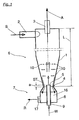
- FIG. 1 shows a hydrocyclone according to the invention, roughly schematically an inlet 2 for the paper fiber-containing suspension S and an accept material outlet 3 for the cleaned suspension, i.e. the accepted substance A.
- the suspension S to be cleaned becomes set in rotation and enters the separating part 6 with a separating cone 1, in which usually increases the speed of rotation again. This will the contained heavy parts ST concentrated on the inner wall of the separating cone 1 and go down into the reject discharge device 17.
- the addition point 5 intended for this has the narrowest Position 4 of the separating cone 1 is the distance a, which is preferably in axial Seen direction, is at most a few millimeters.
- this can Distance a up to 30% of the length L of the hydrocyclone.
- Another sensible one The requirement is that the axial distance to the inlet 2 be kept as large as possible e.g. at least 70% of the length L of the hydrocyclone.
- the heavy parts ST fall, after they have passed the narrowest point 4 of the separating cone 1, into the Discharge chamber 8 from which it, e.g. via a discharge device 17, as reject R be removed.
- This discharge can take place continuously or intermittently.
- the dilution liquid W is replaced by a simple one vertical inlet pipe 9 is added, which is an axial and at the addition point 5 against the discharge direction of the contaminants ST has an opening.
- Circumferential component Vu (see FIG. 5) is so low compared to the axial speed Vax to hold that the angle ⁇ between the resultant of the two vectors and the Axis does not exceed 30 °. Overall, with this type of Add dilution water to a much larger volume distributed and is therefore less harmful to the separation effect.
- the liquid W is particularly advantageously at a certain axial position in the Hydrocyclone entered. Then there is only one opening at the addition point 5. It may be possible to adjust their position in the axial direction.
- FIG. 2 shows a variant for carrying out the method Dilution liquid W via a curved inlet pipe 9 directly in the middle of the entered reject tube 11 below the separating cone 1. It is here the addition point 5 selected so that it is below the narrowest point 4, what but not necessarily so.
- FIG. 3 shows a further possibility for carrying out the method.
- the Dilution liquid W first placed in a flow insert 16 ', in the Inside there is a central displacement body 12, so that an annular Flow cross section arises.
- the ring-shaped jet easily penetrates the one above part of the separating cone. It is also indicated here by arrows, like that Heavy parts ST slide down into the discharge chamber 8 near the wall. she can do this without going through the flow of the dilution liquid into the core flow of the Hydrocyclones to be flushed.
- FIG. 4 shows an axial inflow of the Dilution liquid W through the central inlet pipe 9. It opens inside the Flow insert 16 "via an injector 13 into a central tube 14. This allows Parts of the suspension are sucked out of the hydrocyclone and in the middle again be added, which serves the stable operation and the fiber loss minimized.
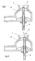
- FIG. 6darsch A hydrocyclone similar to that in FIG. 1 is shown in a perspective view in FIG. 6darsch. More constructive details are visible, but also these Drawing is still greatly simplified.
- FIG. 7 essentially shows the lower part of FIG. 6 in an enlarged form. you thus recognizes more easily that the inlet pipe 9 is screwed in exactly in the middle and in one circular opening opens here above the narrowest point 4. It's easy too mount and can be adjusted axially. With the help of the axial adjustment is one better adjustment of the hydrocyclone to the existing conditions possible.
- the discharge chamber 8 of FIG. 8 has a slightly eccentrically inserted one Inlet pipe 9, but this remains in the radially inner region of the hydrocyclone.
- the outlet cross-section of the inlet pipe 9 keeps one from the wall of the hydrocyclone Distance b a, which is at least 10% of the inner diameter of the hydrocyclone on it Digit is. It must be guaranteed that the already concentrated Heavy parts can no longer be washed in by the dilution liquid.
- the Eccentricity can bring advantages in special cases, e.g. if the hydrocyclone is operated horizontally. It can also be made adjustable.
- the flow inserts shown should only show the principle. More usable Flow applications are conceivable. In particular, their dimensions can be determined by Invoice and simple tests tailored to the respective purpose become.
Landscapes
- Engineering & Computer Science (AREA)
- Mechanical Engineering (AREA)
- Cyclones (AREA)
- Separation Of Solids By Using Liquids Or Pneumatic Power (AREA)
- Paper (AREA)
Claims (17)
- Procédé destiné à l'élimination d'impuretés d'une suspension (S) contenant des fibres de papier en utilisant un hydrocyclone comportant un cône de séparation (1), dans lequel du liquide de dilution (w) est ajouté à la suspension (S) dans la zone située radialement à l'intérieur de l'hydrocyclone, et ce à un écartement axial (a) de l'emplacement le plus étroit du cône de séparation (1), qui correspond à un maximum de 30 % de la longueur (L) de l'hydrocyclone,
caractérise en ce que
le liquide de dilution (W) est ajouté dans un sens d'écoulement qui est orienté à l'opposé du sens d'évacuation des impuretés de l'hydrocyclone, et ce sans rotation ou uniquement avec une rotation dont le vecteur de vitesse d'écoulement résultant de la vitesse périphérique (Vu) et de la vitesse axiale (Vax) au niveau du bord du jet présente un angle (α) de 30° au maximum par rapport à l'axe. - Procédé selon la revendication 1,
caractérisé en ce que
le liquide de dilution (W) est ajouté avec un jet plat. - Procédé selon la revendication 1 ou 2,
caractérisé en ce que
le liquide de dilution (W) est ajouté en un jet rond. - Procédé selon la revendication 1 ou 2,
caractérisé en ce que
le liquide de dilution (W) est ajouté en un jet annulaire. - Procédé selon l'une quelconque des revendications précédentes,
caractérisé en ce que
le liquide de dilution (W) est ajouté au centre à l'aide d'un injecteur (13), et en ce que l'injecteur (13) aspire à partir de la zone annulaire située autour du point d'ajout (5). - Procédé selon l'une quelconque des revendications précédentes,
caractérisé en ce que
le liquide de dilution (W) est ajouté avec une vitesse axiale d'au moins 4 m/s. - Procédé selon l'une quelconque des revendications précédentes,
caractérisé en ce que
une fraction légère est engendrée à partir d'une suspension (S) contenant des fibres de papier en tant que pâte à papier acceptée (A), et en ce que des particules lourdes (ST) sont éliminées en tant que fraction lourde. - Hydrocyclone destiné à la mise en oeuvre du procédé selon l'une quelconque des revendications 1 à 5, avec une entrée (2) pour la suspension (S) à épurer, une sortie (3) de pâte à papier acceptée pour la suspension épurée, une partie de séparation (6) à laquelle est raccordé directement ou indirectement un dispositif d'évacuation 'de rejets (17) pour les particules lourdes, l'hydrocyclone comportant au moins un raccordement pour l'ajout de liquide de dilution (W), et le point d'ajout (5) étant situé dans la sone située radialement à l'intérieur de l'hydrocyclone,
caractérise en ce que
le point d'ajout (5) comporte au moins un orifice, dont le sens d'écoulement est orienté axialement et à l'opposé du sens d'évacuation des impuretés. - Hydrocyclone selon la revendication 8,
caractérisé en ce que
le point d'ajout (5) est situé au niveau d'un emplacement qui, dans la direction axiale, est éloigné de l'entrée (2) de la suspension (S) dans l'hydrocyclone d'au moins 70 % de la longueur (L) de l'hydrocyclone. - Hydrocyclone selon la revendication 9,
caractérisé en ce que
la partie de séparation (6) comprend un cône de séparation (1). - Hydrocyclone selon la revendication 8, 9 ou 10
caractérise en ce que
le point d'ajout (5) fait partie d'un insert d'écoulement (16, 16', 16'') qui est inséré dans l'hydrocyclone. - Hydrocyclone selon la revendication 11,
caractérisé en ce que
l'insert d'écoulement (16, 16', 16'') peut être échangé contre un autre insert d'écoulement, qui est agencé différemment en ce qui concerne son effet d'écoulement. - Hydrocyclone selon la revendication 8, 9, 10, 11 ou 12,
caractérisé en ce que
la section transversale de l'orifice est réglable. - Hydrocyclone selon l'une quelconque des revendications 8 à 13,
caractérise en ce que
la position de l'orifice est réglable. - Hydrocyclone selon l'une quelconque des revendications 8 à 14,
caractérisé en ce que
le point d'ajout (5) est disposé de façon concentrique par rapport au centre de l'hydrocyclone. - Hydrocyclone selon l'une quelconque des revendications 8 à 14,
caractérise en ce que
le point d'ajout (5) est disposé de façon excentrée par rapport au centre de l'hydrocyclone, et à un écartement (b) de la paroi intérieure de l'hydrocyclone, qui correspond à au moins 10 % du diamètre intérieur de l'hydrocyclone à cet emplacement. - Hydrocyclone selon l'une quelconque des revendications 8 à 16,
caractérisé en ce que
le point d'ajout (5) est formé par l'orifice du débouché d'un tube d'amenée (9), qui pénètre dans l'hydrocyclone sous la section transversale la plus étroite de la partie de séparation (6).
Applications Claiming Priority (4)
| Application Number | Priority Date | Filing Date | Title |
|---|---|---|---|
| DE19931166 | 1999-07-06 | ||
| DE19931166 | 1999-07-06 | ||
| DE20004255U | 2000-03-07 | ||
| DE20004255U DE20004255U1 (de) | 1999-07-06 | 2000-03-07 | Hydrozyklon |
Publications (2)
| Publication Number | Publication Date |
|---|---|
| EP1069234A1 EP1069234A1 (fr) | 2001-01-17 |
| EP1069234B1 true EP1069234B1 (fr) | 2004-05-26 |
Family
ID=26054071
Family Applications (1)
| Application Number | Title | Priority Date | Filing Date |
|---|---|---|---|
| EP00112006A Expired - Lifetime EP1069234B1 (fr) | 1999-07-06 | 2000-06-02 | Procédé et dispositif pour enlever des impuretés d'un hydrocyclone |
Country Status (4)
| Country | Link |
|---|---|
| US (1) | US6284096B1 (fr) |
| EP (1) | EP1069234B1 (fr) |
| AT (1) | ATE267909T1 (fr) |
| ES (1) | ES2220296T3 (fr) |
Cited By (1)
| Publication number | Priority date | Publication date | Assignee | Title |
|---|---|---|---|---|
| WO2013117342A1 (fr) | 2012-02-10 | 2013-08-15 | Andritz Energy & Environment Gmbh | Hydrocyclone à appauvrissement en matières fines dans le tamisat inférieur du cyclone |
Families Citing this family (21)
| Publication number | Priority date | Publication date | Assignee | Title |
|---|---|---|---|---|
| US7736501B2 (en) | 2002-09-19 | 2010-06-15 | Suncor Energy Inc. | System and process for concentrating hydrocarbons in a bitumen feed |
| CA2471048C (fr) | 2002-09-19 | 2006-04-25 | Suncor Energy Inc. | Cyclone d'hydrocarbures de mousse bitumineuse |
| DE102004045823A1 (de) * | 2004-09-22 | 2006-03-23 | Voith Paper Patent Gmbh | Verfahren zum Fraktionieren einer wässrigen Papierfasersuspension sowie Hydrozyklon zur Durchführung des Verfahrens |
| SE529771C2 (sv) * | 2005-04-29 | 2007-11-20 | Gl & V Man Hungary Kft Hermina | Hydrocyklonenhet och metod för separering av en fibermassasuspension innehållande relativt tunga föroreningar |
| DE102008057339A1 (de) * | 2008-11-14 | 2010-05-20 | Voith Patent Gmbh | Hydrozyklon |
| DE202008018358U1 (de) | 2008-11-14 | 2013-04-10 | Voith Patent Gmbh | Hydrozyklon |
| CA2689021C (fr) | 2009-12-23 | 2015-03-03 | Thomas Charles Hann | Appareil et procede de regulation de debit par le truchement d'une caisse aspirante |
| JP2012056016A (ja) * | 2010-09-09 | 2012-03-22 | Matluster Technocracy Corp | 湿式分離装置及びこれを用いた研磨材回収システム |
| FI123014B (fi) * | 2010-11-11 | 2012-09-28 | Metso Paper Inc | Pyörrepuhdistimen pohjalaimenninrakenne ja menetelmä pyörrepuhdistimen pohjalaimenninrakenteessa |
| DE102010063196A1 (de) | 2010-12-16 | 2012-06-21 | Voith Patent Gmbh | Hydrozyklon |
| AT512479B1 (de) | 2012-02-10 | 2013-11-15 | Andritz Energy & Environment Gmbh | Verfahren zur feinstoffreduktion im rea-gips |
| RU2538733C2 (ru) * | 2012-11-27 | 2015-01-10 | Закрытое акционерное общество "СОМЭКС" | Гидроциклонная установка с регулируемыми конструктивными параметрами |
| SE538725C2 (sv) * | 2014-06-26 | 2016-11-01 | Valmet Oy | Ångavskiljningsenhet och system för hydrolysförfarande innefattande en ångavskiljningsenhet |
| DE102015002683A1 (de) * | 2014-08-14 | 2016-02-18 | Repa Boltersdorf Gmbh | Verfahren zum Behandeln eines Stoffgemenges aus unterschiedlichen Materialien, Vorrichtung zur Durchführung dieses Verfahrens und ein Zyklon |
| DE102016122225B4 (de) | 2016-11-18 | 2018-11-08 | Voith Patent Gmbh | Hydrozyklonanordnung |
| DE102018122808A1 (de) | 2018-09-18 | 2020-03-19 | Voith Patent Gmbh | Steuerverfahren einer Reinigungsvorrichtung mit Schwerteil-Abscheider |
| CN113272069B (zh) * | 2019-01-10 | 2023-04-21 | 维美德技术有限公司 | 水力旋流器废料室 |
| WO2020157383A1 (fr) * | 2019-01-31 | 2020-08-06 | Andritz Oy | Chambre de rejet d'un épurateur centrifuge et épurateur centrifuge |
| FI128719B (en) | 2019-05-02 | 2020-10-30 | Andritz Oy | Vortex cleaner reject chamber and vortex cleaner |
| DE102022110164A1 (de) | 2021-08-26 | 2023-03-02 | Voith Patent Gmbh | Hydrozyklonanordnung |
| CN116870541A (zh) * | 2023-07-07 | 2023-10-13 | 北京清新环境技术股份有限公司 | 一种脱硫浆液脱水系统 |
Family Cites Families (9)
| Publication number | Priority date | Publication date | Assignee | Title |
|---|---|---|---|---|
| SE346705B (fr) * | 1970-04-01 | 1972-07-17 | N Wikdahl | |
| US3720315A (en) * | 1971-01-18 | 1973-03-13 | Clark & Vicario Corp | Stabilizing papermaking system cleaner operation |
| US3785489A (en) * | 1971-07-14 | 1974-01-15 | Celleco Ab | Cyclone separator with underflow diluter |
| US4151083A (en) * | 1974-09-10 | 1979-04-24 | Dove Norman F | Apparatus and method for separating heavy impurities from feed stock |
| US4356084A (en) * | 1979-04-06 | 1982-10-26 | The Black Clawson Company | Self-sealing valve assembly to facilitate unplugging of a centrifugal cleaner |
| CA1138378A (fr) * | 1980-03-13 | 1982-12-28 | Jacek J. Macierewicz | Dispositif axial d'elutriation pour l'orifice de rejet d'un hydrocyclone |
| FR2478489B1 (fr) * | 1980-03-21 | 1985-08-30 | Centre Tech Ind Papier | Procede et dispositif pour la separation de particules dans un fluide, notamment pour l'epuration de suspensions papetieres |
| US5069751A (en) * | 1990-08-09 | 1991-12-03 | Kamyr, Inc. | Hydrocyclone deinking of paper during recycling |
| US6109451A (en) * | 1998-11-13 | 2000-08-29 | Grimes; David B. | Through-flow hydrocyclone and three-way cleaner |
-
2000
- 2000-06-02 AT AT00112006T patent/ATE267909T1/de active
- 2000-06-02 ES ES00112006T patent/ES2220296T3/es not_active Expired - Lifetime
- 2000-06-02 EP EP00112006A patent/EP1069234B1/fr not_active Expired - Lifetime
- 2000-07-05 US US09/610,616 patent/US6284096B1/en not_active Expired - Lifetime
Cited By (1)
| Publication number | Priority date | Publication date | Assignee | Title |
|---|---|---|---|---|
| WO2013117342A1 (fr) | 2012-02-10 | 2013-08-15 | Andritz Energy & Environment Gmbh | Hydrocyclone à appauvrissement en matières fines dans le tamisat inférieur du cyclone |
Also Published As
| Publication number | Publication date |
|---|---|
| US6284096B1 (en) | 2001-09-04 |
| EP1069234A1 (fr) | 2001-01-17 |
| ES2220296T3 (es) | 2004-12-16 |
| ATE267909T1 (de) | 2004-06-15 |
Similar Documents
| Publication | Publication Date | Title |
|---|---|---|
| EP1069234B1 (fr) | Procédé et dispositif pour enlever des impuretés d'un hydrocyclone | |
| DE69129264T2 (de) | Zentrifugalreiniger | |
| EP0034780B1 (fr) | Dispositif de triage rotatif | |
| DE754339C (de) | Verfahren und Vorrichtung zum Entfernen von schweren Teilchen unter Fliehkraftwirkung aus einer Aufschwemmung, insbesondere von Zellstoff, Papierstoff u. dgl. | |
| DE69113932T2 (de) | Drucksortierer für eine faserhaltige Stoffsuspension. | |
| DE1761600C3 (de) | Vorrichtung zum Sichten von Faserstoffaufschwemmungen | |
| EP2516733A1 (fr) | Procédé et dispositif de tamisage pour le tamisage d'une suspension de matière fibreuse | |
| EP1215335B1 (fr) | Tamis sous pression pour l'épuration de pâte à papier contenant des impuretés | |
| AT510253B1 (de) | Zweistufige pulpensiebvorrichtung mit zwei stationären zylindrischen sieben | |
| DE2818029A1 (de) | Vorrichtung zum sortieren von faserstoffsuspensionen | |
| DE2753413C3 (de) | Drucksortierer | |
| DE102011088102A1 (de) | Siebvorrichtung zum Sieben einer Faserstoffsuspension | |
| EP2425052A2 (fr) | Procédé de traitement d'une suspension de matière fibreuse et dispositif de tamisage permettant la mise en oeuvre dudit procédé | |
| DE2757175A1 (de) | Vorrichtung und verfahren zum zermahlen und aufbereiten von abfallstoffen | |
| EP1799903B1 (fr) | Procede pour fractionner une suspension aqueuse de fibres a papier et hydrocyclone pour la mise en oeuvre dudit procede | |
| DE3001448C2 (de) | Drucksortierer | |
| DE10115298A1 (de) | Drucksortierer zum Entfernen von Störstoffen aus einer störstoffhaltigen Papierfasersuspension | |
| EP1598477A1 (fr) | Tamis sous pression pour tamiser une suspension de fibres | |
| DE20004255U1 (de) | Hydrozyklon | |
| DE4432842C2 (de) | Verfahren zum Ausbringen unerwünschter Feststoffpartikel aus einer wässerigen Faserstoffsuspension sowie Vorrichtung zu seiner Ausführung | |
| EP1462568A1 (fr) | Classeur pour la purification d'une suspension fibreuse | |
| DE102005016192A1 (de) | Verfahren zum Auflösen und Reinigen von störstoffhaltigen Papierrohrstoffen | |
| DE1442501A1 (de) | Verfahren zum Ausscheiden von Fremdkoerpern aus einem fliessfaehigen Medium mittels eines Zyklons und Zyklon zur Ausuebung des Verfahrens | |
| EP0616072A1 (fr) | Procédé de triage d'un suspension de fibres et dispositif de triage pour son application | |
| DE102024113569A1 (de) | Unterlauf-Austragsvorrichtung und Hydrozyklon mit einer solchen Unterlauf-Austragsvorrichtung |
Legal Events
| Date | Code | Title | Description |
|---|---|---|---|
| PUAI | Public reference made under article 153(3) epc to a published international application that has entered the european phase |
Free format text: ORIGINAL CODE: 0009012 |
|
| AK | Designated contracting states |
Kind code of ref document: A1 Designated state(s): AT BE CH CY DE DK ES FI FR GB GR IE IT LI LU MC NL PT SE |
|
| AX | Request for extension of the european patent |
Free format text: AL;LT;LV;MK;RO;SI |
|
| RAP1 | Party data changed (applicant data changed or rights of an application transferred) |
Owner name: VOITH PAPER PATENT GMBH |
|
| 17P | Request for examination filed |
Effective date: 20010717 |
|
| AKX | Designation fees paid |
Free format text: AT BE CH CY DE DK ES FI FR GB GR IE IT LI LU MC NL PT SE |
|
| 17Q | First examination report despatched |
Effective date: 20030522 |
|
| GRAP | Despatch of communication of intention to grant a patent |
Free format text: ORIGINAL CODE: EPIDOSNIGR1 |
|
| GRAS | Grant fee paid |
Free format text: ORIGINAL CODE: EPIDOSNIGR3 |
|
| GRAA | (expected) grant |
Free format text: ORIGINAL CODE: 0009210 |
|
| AK | Designated contracting states |
Kind code of ref document: B1 Designated state(s): AT BE CH CY DE DK ES FI FR GB GR IE IT LI LU MC NL PT SE |
|
| PG25 | Lapsed in a contracting state [announced via postgrant information from national office to epo] |
Ref country code: NL Free format text: LAPSE BECAUSE OF FAILURE TO SUBMIT A TRANSLATION OF THE DESCRIPTION OR TO PAY THE FEE WITHIN THE PRESCRIBED TIME-LIMIT Effective date: 20040526 Ref country code: CY Free format text: LAPSE BECAUSE OF FAILURE TO SUBMIT A TRANSLATION OF THE DESCRIPTION OR TO PAY THE FEE WITHIN THE PRESCRIBED TIME-LIMIT Effective date: 20040526 Ref country code: IE Free format text: LAPSE BECAUSE OF FAILURE TO SUBMIT A TRANSLATION OF THE DESCRIPTION OR TO PAY THE FEE WITHIN THE PRESCRIBED TIME-LIMIT Effective date: 20040526 |
|
| REG | Reference to a national code |
Ref country code: GB Ref legal event code: FG4D Free format text: NOT ENGLISH |
|
| REG | Reference to a national code |
Ref country code: CH Ref legal event code: EP |
|
| PG25 | Lapsed in a contracting state [announced via postgrant information from national office to epo] |
Ref country code: LU Free format text: LAPSE BECAUSE OF NON-PAYMENT OF DUE FEES Effective date: 20040602 |
|
| GBT | Gb: translation of ep patent filed (gb section 77(6)(a)/1977) |
Effective date: 20040526 |
|
| PG25 | Lapsed in a contracting state [announced via postgrant information from national office to epo] |
Ref country code: MC Free format text: LAPSE BECAUSE OF NON-PAYMENT OF DUE FEES Effective date: 20040630 Ref country code: CH Free format text: LAPSE BECAUSE OF NON-PAYMENT OF DUE FEES Effective date: 20040630 Ref country code: LI Free format text: LAPSE BECAUSE OF NON-PAYMENT OF DUE FEES Effective date: 20040630 Ref country code: BE Free format text: LAPSE BECAUSE OF NON-PAYMENT OF DUE FEES Effective date: 20040630 |
|
| REG | Reference to a national code |
Ref country code: IE Ref legal event code: FG4D Free format text: GERMAN |
|
| REF | Corresponds to: |
Ref document number: 50006562 Country of ref document: DE Date of ref document: 20040701 Kind code of ref document: P |
|
| PG25 | Lapsed in a contracting state [announced via postgrant information from national office to epo] |
Ref country code: GR Free format text: LAPSE BECAUSE OF FAILURE TO SUBMIT A TRANSLATION OF THE DESCRIPTION OR TO PAY THE FEE WITHIN THE PRESCRIBED TIME-LIMIT Effective date: 20040826 Ref country code: DK Free format text: LAPSE BECAUSE OF FAILURE TO SUBMIT A TRANSLATION OF THE DESCRIPTION OR TO PAY THE FEE WITHIN THE PRESCRIBED TIME-LIMIT Effective date: 20040826 |
|
| REG | Reference to a national code |
Ref country code: SE Ref legal event code: TRGR |
|
| NLV1 | Nl: lapsed or annulled due to failure to fulfill the requirements of art. 29p and 29m of the patents act | ||
| ET | Fr: translation filed | ||
| REG | Reference to a national code |
Ref country code: ES Ref legal event code: FG2A Ref document number: 2220296 Country of ref document: ES Kind code of ref document: T3 |
|
| REG | Reference to a national code |
Ref country code: IE Ref legal event code: FD4D |
|
| BERE | Be: lapsed |
Owner name: VOITH PAPER PATENT G.M.B.H. Effective date: 20040630 |
|
| REG | Reference to a national code |
Ref country code: CH Ref legal event code: PL |
|
| PLBE | No opposition filed within time limit |
Free format text: ORIGINAL CODE: 0009261 |
|
| STAA | Information on the status of an ep patent application or granted ep patent |
Free format text: STATUS: NO OPPOSITION FILED WITHIN TIME LIMIT |
|
| 26N | No opposition filed |
Effective date: 20050301 |
|
| PG25 | Lapsed in a contracting state [announced via postgrant information from national office to epo] |
Ref country code: PT Free format text: LAPSE BECAUSE OF NON-PAYMENT OF DUE FEES Effective date: 20041026 |
|
| PGFP | Annual fee paid to national office [announced via postgrant information from national office to epo] |
Ref country code: ES Payment date: 20120627 Year of fee payment: 13 |
|
| PGFP | Annual fee paid to national office [announced via postgrant information from national office to epo] |
Ref country code: AT Payment date: 20120613 Year of fee payment: 13 |
|
| PGFP | Annual fee paid to national office [announced via postgrant information from national office to epo] |
Ref country code: GB Payment date: 20130619 Year of fee payment: 14 Ref country code: DE Payment date: 20130620 Year of fee payment: 14 Ref country code: SE Payment date: 20130619 Year of fee payment: 14 |
|
| PGFP | Annual fee paid to national office [announced via postgrant information from national office to epo] |
Ref country code: FI Payment date: 20130613 Year of fee payment: 14 Ref country code: FR Payment date: 20130703 Year of fee payment: 14 Ref country code: IT Payment date: 20130625 Year of fee payment: 14 |
|
| REG | Reference to a national code |
Ref country code: DE Ref legal event code: R119 Ref document number: 50006562 Country of ref document: DE |
|
| PG25 | Lapsed in a contracting state [announced via postgrant information from national office to epo] |
Ref country code: SE Free format text: LAPSE BECAUSE OF NON-PAYMENT OF DUE FEES Effective date: 20140603 Ref country code: FI Free format text: LAPSE BECAUSE OF NON-PAYMENT OF DUE FEES Effective date: 20140602 |
|
| REG | Reference to a national code |
Ref country code: SE Ref legal event code: EUG |
|
| REG | Reference to a national code |
Ref country code: AT Ref legal event code: MM01 Ref document number: 267909 Country of ref document: AT Kind code of ref document: T Effective date: 20140602 |
|
| GBPC | Gb: european patent ceased through non-payment of renewal fee |
Effective date: 20140602 |
|
| REG | Reference to a national code |
Ref country code: DE Ref legal event code: R119 Ref document number: 50006562 Country of ref document: DE Effective date: 20150101 |
|
| REG | Reference to a national code |
Ref country code: FR Ref legal event code: ST Effective date: 20150227 |
|
| PG25 | Lapsed in a contracting state [announced via postgrant information from national office to epo] |
Ref country code: IT Free format text: LAPSE BECAUSE OF NON-PAYMENT OF DUE FEES Effective date: 20140602 Ref country code: DE Free format text: LAPSE BECAUSE OF NON-PAYMENT OF DUE FEES Effective date: 20150101 |
|
| PG25 | Lapsed in a contracting state [announced via postgrant information from national office to epo] |
Ref country code: FR Free format text: LAPSE BECAUSE OF NON-PAYMENT OF DUE FEES Effective date: 20140630 Ref country code: AT Free format text: LAPSE BECAUSE OF NON-PAYMENT OF DUE FEES Effective date: 20140602 Ref country code: GB Free format text: LAPSE BECAUSE OF NON-PAYMENT OF DUE FEES Effective date: 20140602 |
|
| REG | Reference to a national code |
Ref country code: ES Ref legal event code: FD2A Effective date: 20150727 |
|
| PG25 | Lapsed in a contracting state [announced via postgrant information from national office to epo] |
Ref country code: ES Free format text: LAPSE BECAUSE OF NON-PAYMENT OF DUE FEES Effective date: 20140603 |