EP1069224A1 - Felting needle - Google Patents
Felting needle Download PDFInfo
- Publication number
- EP1069224A1 EP1069224A1 EP00109536A EP00109536A EP1069224A1 EP 1069224 A1 EP1069224 A1 EP 1069224A1 EP 00109536 A EP00109536 A EP 00109536A EP 00109536 A EP00109536 A EP 00109536A EP 1069224 A1 EP1069224 A1 EP 1069224A1
- Authority
- EP
- European Patent Office
- Prior art keywords
- diameter
- needle
- transition
- working part
- clamping part
- Prior art date
- Legal status (The legal status is an assumption and is not a legal conclusion. Google has not performed a legal analysis and makes no representation as to the accuracy of the status listed.)
- Granted
Links
- 238000009950 felting Methods 0.000 title claims abstract description 23
- 230000007704 transition Effects 0.000 claims abstract description 62
- 239000000835 fiber Substances 0.000 description 27
- 238000004140 cleaning Methods 0.000 description 6
- 239000000463 material Substances 0.000 description 5
- 238000004519 manufacturing process Methods 0.000 description 3
- 238000000034 method Methods 0.000 description 3
- 230000008569 process Effects 0.000 description 3
- 230000035508 accumulation Effects 0.000 description 2
- 238000009825 accumulation Methods 0.000 description 2
- 230000007423 decrease Effects 0.000 description 2
- 239000004745 nonwoven fabric Substances 0.000 description 2
- 230000009467 reduction Effects 0.000 description 2
- 230000008901 benefit Effects 0.000 description 1
- 230000003247 decreasing effect Effects 0.000 description 1
- 230000008021 deposition Effects 0.000 description 1
- 238000005137 deposition process Methods 0.000 description 1
- 230000004907 flux Effects 0.000 description 1
- 238000003780 insertion Methods 0.000 description 1
- 230000037431 insertion Effects 0.000 description 1
- 239000002557 mineral fiber Substances 0.000 description 1
- 239000000203 mixture Substances 0.000 description 1
- 239000007787 solid Substances 0.000 description 1
- 238000003860 storage Methods 0.000 description 1
- 239000012209 synthetic fiber Substances 0.000 description 1
- 229920002994 synthetic fiber Polymers 0.000 description 1
Images


Classifications
-
- D—TEXTILES; PAPER
- D04—BRAIDING; LACE-MAKING; KNITTING; TRIMMINGS; NON-WOVEN FABRICS
- D04H—MAKING TEXTILE FABRICS, e.g. FROM FIBRES OR FILAMENTARY MATERIAL; FABRICS MADE BY SUCH PROCESSES OR APPARATUS, e.g. FELTS, NON-WOVEN FABRICS; COTTON-WOOL; WADDING ; NON-WOVEN FABRICS FROM STAPLE FIBRES, FILAMENTS OR YARNS, BONDED WITH AT LEAST ONE WEB-LIKE MATERIAL DURING THEIR CONSOLIDATION
- D04H18/00—Needling machines
- D04H18/02—Needling machines with needles
Definitions
- the invention relates to a needle with the features of the preamble of claim 1 or of the claim 2nd
- Loose and disorganized are made during felt production superimposed fibers by a machine between a multi-perforated scraper plate and one too perforated bed plate. This mixture of fibers is repeated with a larger number of special Pierced needles (felting needles). The felting needles work thereby binding the fiber to one another so that the Gradually compacted web and ultimately a solid Felt is made.
- the fibers come apart from natural fibers and synthetic fibers also use recycled fibers that are used in usually have an increased tendency to join fix the needles and form deposits.
- Deposits form after a certain period of time the machine for making the felt.
- the deposits can clog the needles to such an extent that the Needles are no longer able to pass through the holes of the To penetrate the scraper plate. This will cause deposits Broken needles and lost production.
- the air flow between negatively affected the needles with the result that the deposits accelerate.
- For needle cleaning production must be interrupted. When cleaning the needle needle breakage occurs frequently.
- the material is solidified during the needle process. To Beginning, i.e. when pinning, the material is relative loose and voluminous. Penetrates the needle with its shaft section or their intermediate area in the material, it creates holes with shaft diameter or the diameter of the intermediate section that is larger than that Diameter of the working part. This results in a bad one Surface quality of the felt.
- DE 1760440 C3 describes felting needles with a long one known straight shaft, which at its upper end to the Is angled in a needle board.
- the shaft tapers at its other end to a reduced one Cross-section and is provided with hooks.
- This Section forms a working part which is used to matt the Nonwoven serves.
- the transition between the work part and the remaining shaft serving as a clamping part is relative steep.
- DE 3704471 A1 describes a device for needling a mineral fiber fleece known.
- the one on a needle board held felting needles extend parallel to each other away from the needle board through corresponding openings one Scraper plate. Between this and a bed plate, the also has openings for the felting needles is a Formed gap through which the nonwoven fabric is passed.
- the felting needles have a cylindrical, angled top and relatively thick shaft, one section of which is held in the needle board. Between the clamping part and the serrated working part is a transition area trained, the length of which is hardly greater than that Diameter of the shaft area.
- a fork needle is known from DE-OS 2222881, which has a toothless work area. This connects to one another via a conical intermediate area cylindrical shaft. The working part is on his The outside is smooth and only on his Provide the free end with a mouth-like fork. Depending on Embodiment may have a more or less steep transition area be provided in the form of a cone.
- Fork needles are used to consolidate nonwovens to structure in a follow-up process. You tend because of little of the smooth, toothless flanks of the working part to detach fibers from the fiber structure and take them with you.
- Felting needles with a serrated working part tend to come off fibers pulled out of the fiber structure on their shaft accumulate.
- the shaft is enough when needling the fibers partly in the work area between the scraper plate and Bed plate.
- the fibers that are pulled out form deposits in the form of fiber rings, which differ from the relatively thin Working part on the short transition area to the cylindrical shaft area between the needle board and push the scraper plate. In doing so, they are expanded and tightened.
- Exceed these deposits tolerable measure is the insertion of the needles in the Fleece hampers because the needle board is no longer close enough can be brought up to the scraper plate. There are therefore from time to time depending on the nonwoven material used Cleaning actions required. Because of the large number the needle held on a needle board is one Cleaning laborious and time consuming.
- the needle according to the invention is characterized in that that between the toothed working part and the Toothed clamping part is a relatively slim transition part or transition area is formed, at least has a range in which the diameter of the shaft diameter to the diameter of the working part gradually decreased.
- the length of this area if necessary also be divided into several sections overall is at least twice as long as that Length of the toothed working part.
- the transition part preferably takes the whole Space between the needle board and the respective work part a (claim 2). There is a lean transition which leads to less deposits on the needle form.
- the working part of the Needle can be made slimmer than conventional ones Needles.
- the transition is preferably longer 11 better still 20 mm (claim 3).
- the invention Needle can be felt needles with single, double or triple Replace diameter reduction. So that drops variety of types to be provided by the needle manufacturer.
- Another advantage is that the shaft area, the when needling into the work area between the scraper plate and bed plate arrives, a smaller diameter compared to conventional needles. Thereby the openings created by the shaft area in the manufactured felt smaller in diameter. Thus improved the surface quality of the felt.
- the transition part is preferably conical in one continuous part.
- the cone can be a straight one Be a circular truncated cone. This means a generatrix this area is a straight line.
- the Cone can also be formed by a non-straight cone. A generatrix of the transition part is then arcuate.
- the working part and the clamping part is preferably arranged coaxially with one another. If necessary, however, can also deviate from this become. It is also preferred that the working part has a has constant diameter and also preferably without changing the diameter smooth to the transition part connects.
- the transition part takes the whole Space between the needle board and the working part.
- the Total length of the transition part can be due to the needle dimensions less than twice the length of the part his.
- the needle consists of three areas: Working part, transition part and shaft part, the complete sitting in the needle board.
- transition part is longer is intended as the thickness of the for attaching the needles Needle boards. Regardless of the total length of the The transition part begins with the transition part according to the invention Embodiment according to claim 2 immediately on the needle board.
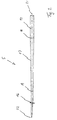
- Figure 1 is a device 1 for needling a Fleece illustrated. Belongs to device 1 a needle board 2, which is driven, for example, by an eccentric is and a reciprocating motion in one direction illustrated by an arrow 3.
- the needle board 2 has openings 4 for mounting and storage of needles 5 on.
- the needles 5 extend in the Distance and parallel to each other away from the needle board 2. They protrude through stripping openings 6 in a stripping plate 7 are formed. This is at some distance arranged to a bed plate 8 and lays with this an intermediate space 9, through the loose and disordered fibers lying in one in FIG. 1 by an arrow 11 designated direction. In the further course these fibers become by the up and down movement of the needles 5 consolidated into a fleece.
- Openings 12 are provided in the bed plate 8, each having an opening 12 of the bed plate 8 with a Opening 6 of the scraper plate 7 is aligned.
- the needles 5 are constructed to match one another. They each have one held in the needle board 2 Clamping part 14 and one with barbs or hooks 15 provided working part 16. Between the clamping part 14 and the working part 16 is a transition part 17 arranged. The transition part 17 extends from the Clamping part 14 up to the working part 16, being in immediate vicinity of the needle board 2 begins.
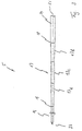
- FIG 2 is a needle 5 to illustrate the Proportions shown.
- the transition part 17 decreases the diameter of the larger one, at the transition point 18 value to be measured at a lower value, which at a transition point 19 is to be measured, at which the working part 16 begins.
- the transition part 17 is coaxial with a longitudinal axis 21 of the needle 5 arranged and forms a total a contiguous area for customization of the diameter.
- the clamping part 14 and Working part 16 arranged coaxially to the longitudinal axis 21. The diameter decreases along the longitudinal axis 21 of the transition part 17 steady and linear.
- the between the Practice crossing points 18, 19 length of the transition part to be measured 17 is at least twice the length of the Working part 16, i.e. the distance of the transition point 19 from one formed at the free end of the needle 5 Tip 22. This makes the transition part very slim and long. It has no levels or paragraphs.
- the device 1 works as follows:
- the needle board 2 is in quick succession moved back and forth in the direction of arrow 3, that the needles 5 periodically clear the space 9 and puncture. Solidify the hooks 15 of the working parts 16 the individual fibers form a fleece. At this process still exists, especially for the first needles coming into contact with unconsolidated fibers the risk that individual fiber filaments are taken away and are pulled through the stripping openings 6 and on deposit the needle 5. With the needles 5 according to the invention this tendency is due to the long and lean training the transition parts 17 counteracted. The needles 5 draw at least some nonwoven materials, and in particular with recycled fibers fewer fibers due to the Scraper openings 6.
- FIG 3 is a slightly modified embodiment the needle 5 illustrates.
- the one from the transition part 17 formed area is in two sub-areas 17a, 17b, in which the diameter of the needle 5 reduced from the shaft diameter to the working part diameter.
- the sub-area 17a borders on the transition point 19, while the section 17b to the transition point 18 borders.
- Between the partial areas 17a, 17b an intermediate cylindrical portion 17c is formed.
- this also applies advantageously the transition part 17 immediately after the needle board 2 begins, i.e. that the transition point 18 aligned with the underside of the needle board 2.
- the subareas 17a, 17b, in which the tapering of the needle 5 taken together have a length that is the same or greater than twice the length of the working part 16, i.e. the distance between the transition point 19 and the tip 22.
- the latter applies accordingly to those in Figures 4 and Figure 5 illustrates embodiment of the needle 5. Die The above description applies accordingly, but with an exception.
- the partial areas 17a, 17b each lie on the mantle of a narrow cone, i.e. the diameter takes on the tip 22 in these partial areas 17a, 17b down.
- the diameter reduction is at 4 linear for the partial region 17a, not for section 17b.
- the diameter increases to the top starting from the transition point 18 initially stronger and then less strong.
- the cone is therefore curvilinear.
- Such a cone can also be used instead of the cone in section 17a or in the embodiment of Figure 2 instead of the straight slim truncated cone is formed in the transition part 17 his.
- transition part 17 is provided which is designed as a long, slender truncated cone.
- the length this transition part 17 is at least twice as long like the working part. This results in a very slim transition area, which tends little to fibers pull out of the fleece and collect. Should nevertheless form fiber deposits, these are easy to remove.
Landscapes
- Engineering & Computer Science (AREA)
- Textile Engineering (AREA)
- Nonwoven Fabrics (AREA)
Abstract
Description
Die Erfindung betrifft eine Nadel mit den Merkmalen
des Oberbegriffs des Patentanspruchs 1 oder des Patentanspruchs
2.The invention relates to a needle with the features
of the preamble of
Bei der Filzherstellung werden lose und ungeordnet übereinander liegenden Fasern durch eine Maschine zwischen einer vielfach gelochten Abstreiferplatte und einer ebenfalls gelochten Bettplatte geführt. Dieses Fasergemisch wird wiederholt mit einer größeren Anzahl spezieller Nadeln (Filznadeln) durchstochen. Die Filznadeln bewirken dabei eine Bindung der Faser untereinander, so dass die Bahn nach und nach verdichtet und letztlich ein fester Filz hergestellt wird. Als Fasern kommen außer Naturfasern und Kunstfasern auch Recyclingfasern zum Einsatz, die in der Regel jedoch eine verstärkte Tendenz haben, sich an den Nadeln festzusetzen und Ablagerungen zu bilden.Loose and disorganized are made during felt production superimposed fibers by a machine between a multi-perforated scraper plate and one too perforated bed plate. This mixture of fibers is repeated with a larger number of special Pierced needles (felting needles). The felting needles work thereby binding the fiber to one another so that the Gradually compacted web and ultimately a solid Felt is made. The fibers come apart from natural fibers and synthetic fibers also use recycled fibers that are used in usually have an increased tendency to join fix the needles and form deposits.
Ablagerungen bilden sich nach einer gewissen Laufzeit der Maschine zum Herstellen des Filzes. Die Ablagerungen können die Nadeln in einem solchen Maß zusetzen, dass die Nadeln nicht länger in der Lage sind, durch die Löcher der Abstreiferplatte durchzudringen. Diese Ablagerungen verursachen Nadelbrüche und Produktionsausfälle. Sobald der Ablagerungsprozess beginnt, wird die Luftströmung zwischen den Nadeln negativ beeinflusst, mit dem Ergebnis, dass sich die Ablagerungen noch beschleunigen. Zur Nadelreinigung muss die Produktion unterbrochen werden. Bei der Nadelreinigung kommt es häufig zum Nadelbruch.Deposits form after a certain period of time the machine for making the felt. The deposits can clog the needles to such an extent that the Needles are no longer able to pass through the holes of the To penetrate the scraper plate. This will cause deposits Broken needles and lost production. Once the Deposition process begins, the air flow between negatively affected the needles, with the result that the deposits accelerate. For needle cleaning production must be interrupted. When cleaning the needle needle breakage occurs frequently.
Beim Nadelprozess wird das Material verfestigt. Zu Anfang, d.h. beim Vornadeln, ist das Material relativ locker und voluminös. Dringt die Nadel mit ihrem Schaftabschnitt oder ihrem Zwischenbereich in das Material ein, erzeugt sie Löcher mit Schaftdurchmesser oder dem Durchmesser des Zwischenabschnitts, der größer ist als der Durchmesser des Arbeitsteils. Dies ergibt eine schlechte Oberflächenqualität des Filzes.The material is solidified during the needle process. To Beginning, i.e. when pinning, the material is relative loose and voluminous. Penetrates the needle with its shaft section or their intermediate area in the material, it creates holes with shaft diameter or the diameter of the intermediate section that is larger than that Diameter of the working part. This results in a bad one Surface quality of the felt.
Aus der DE 1760440 C3 sind Filznadeln mit einem langen geraden Schaft bekannt, der an seinem oberen Ende zum Einspannen in einem Nadelbrett abgewinkelt ist. Der Schaft verjüngt sich an seinem anderen Ende zu einem reduzierten Querschnitt und ist im weiteren mit Haken versehen. Dieser Abschnitt bildet einen Arbeitsteil, der zum Verfilzen des Faservlies dient.DE 1760440 C3 describes felting needles with a long one known straight shaft, which at its upper end to the Is angled in a needle board. The shaft tapers at its other end to a reduced one Cross-section and is provided with hooks. This Section forms a working part which is used to matt the Nonwoven serves.
Der Übergang zwischen dem Arbeitsteil und dem übrigen, als Einspannteil dienenden Schaft ist relativ steil.The transition between the work part and the remaining shaft serving as a clamping part is relative steep.
Aus der DE 3704471 A1 ist eine Vorrichtung zum Nadeln eines Mineralfaservlieses bekannt. Die an einem Nadelbrett gehaltenen Filznadeln erstrecken sich parallel zueinander von dem Nadelbrett weg durch entsprechende Öffnungen einer Abstreifplatte. Zwischen dieser und einer Bettplatte, die ebenfalls Öffnungen für die Filznadeln aufweist, ist ein Spalt ausgebildet, durch den das Faservlies geführt wird. Die Filznadelr weisen einen zylindrischen, oben abgewinkelten und relativ dicken Schaft auf, von dem ein Abschnitt in dem Nadelbrett gehalten ist. Zwischen dem Einspannteil und dem gezahnten Arbeitsteil ist ein Übergangsbereich ausgebildet, dessen Länge kaum größer ist als der Durchmesser des Schaftbereichs.DE 3704471 A1 describes a device for needling a mineral fiber fleece known. The one on a needle board held felting needles extend parallel to each other away from the needle board through corresponding openings one Scraper plate. Between this and a bed plate, the also has openings for the felting needles is a Formed gap through which the nonwoven fabric is passed. The felting needles have a cylindrical, angled top and relatively thick shaft, one section of which is held in the needle board. Between the clamping part and the serrated working part is a transition area trained, the length of which is hardly greater than that Diameter of the shaft area.
Auf dem zylindrischen Schaft können sich Ablagerungen bilden.There may be deposits on the cylindrical shaft form.
Aus der DE-OS 2222881 ist eine Gabelnadel bekannt, die einen ungezahnten Arbeitsbereich aufweist. Dieser schließt über einen konischen Zwischenbereich an einen zylindrischen Schaft an. Der Arbeitsteil ist an seiner Außenseite glatt ausgebildet und lediglich an seinem freien Ende mit einer maulartigen Gabel versehen. Je nach Ausführungsform kann ein mehr oder weniger steiler Übergangsbereich in Form eines Konus vorgesehen sein. A fork needle is known from DE-OS 2222881, which has a toothless work area. This connects to one another via a conical intermediate area cylindrical shaft. The working part is on his The outside is smooth and only on his Provide the free end with a mouth-like fork. Depending on Embodiment may have a more or less steep transition area be provided in the form of a cone.
Gabelnadeln werden verwendet, um verfestigte Vliese in einem Folgeprozess zu strukturieren. Sie neigen wegen der glatten ungezahnten Flanken des Arbeitsteils wenig dazu, Fasern aus dem Faserverband herauszulösen und mitzunehmen.Fork needles are used to consolidate nonwovens to structure in a follow-up process. You tend because of little of the smooth, toothless flanks of the working part to detach fibers from the fiber structure and take them with you.
Aus der US-PS 3.753.412 sind weitere Filznadeln mit gezahnten Arbeitsteilen bekannt. Zwischen dem jeweiligen gezahnten Arbeitsteil und einem zylindrischen Schaft ist ein Übergangsteil angeordnet, der relativ kurz ausgebildet ist.From US-PS 3,753,412 additional felting needles are also available serrated work parts known. Between each serrated working part and a cylindrical shaft arranged a transition part, which is relatively short is.
Filznadeln mit gezahntem Arbeitsteil neigen dazu, aus dem Faserverband herausgezogene Fasern auf ihrem Schaft anzusammeln. Der Schaft reicht beim Vernadeln der Fasern teilweise in den Arbeitsraum zwischen Abstreiferplatte und Bettplatte. Die herausgezogenen Fasern bilden Ablagerungen in Form von Faserringen, welche sich vom relativ dünnen Arbeitsteil über den kurzen Übergangsbereich auf den zylindrischen Schaftbereich zwischen dem Nadelbrett und der Abstreifplatte schieben. Dabei werden sie aufgeweitet und festgezogen. Übersteigen diese Ablagerungen ein tolerierbares Maß, wird das Einstechen der Nadeln in das Vlies behindert, weil das Nadelbrett nicht mehr nahe genug an die Abstreifplatte herangeführt werden kann. Es sind deshalb je nach verwendetem Vliesmaterial von Zeit zu Zeit Reinigungsaktionen erforderlich. Aufgrund der großen Zahl der an einen Nadelbrett gehaltenen Nadeln ist eine solche Reinigung mühsam und zeitaufwendig.Felting needles with a serrated working part tend to come off fibers pulled out of the fiber structure on their shaft accumulate. The shaft is enough when needling the fibers partly in the work area between the scraper plate and Bed plate. The fibers that are pulled out form deposits in the form of fiber rings, which differ from the relatively thin Working part on the short transition area to the cylindrical shaft area between the needle board and push the scraper plate. In doing so, they are expanded and tightened. Exceed these deposits tolerable measure, is the insertion of the needles in the Fleece hampers because the needle board is no longer close enough can be brought up to the scraper plate. There are therefore from time to time depending on the nonwoven material used Cleaning actions required. Because of the large number the needle held on a needle board is one Cleaning laborious and time consuming.
Davon ausgehend ist es Aufgabe der Erfindung, die Reinigung der Nadeln zu erleichtern und/oder die Neigung der Nadeln zum Akkumulieren von Fasern zu vermindern. Based on this, it is an object of the invention Facilitate cleaning of the needles and / or inclination the needles to accumulate fibers.
Diese Aufgabe wird mit Nadeln nach Anspruch 1, 2 oder
Anspruch 3 gelöst.This object is achieved with needles according to
Die erfindungsgemaße Nadel zeichnet sich dadurch aus, dass zwischen dem gezahnten Arbeitsteil und dem ungezahnten Einspannteil ein relativ schlanker Übergangsteil bzw. Übergangsbereich ausgebildet ist, der zumindest einen Bereich aufweist, in dem sich der Durchmesser von dem Schaftdurchmesser auf den Durchmesser des Arbeitsteils allmählich verringert. Die Länge dieses Bereichs, der bedarfsweise auch in mehrere Teilbereiche aufgeteilt sein kann, ist insgesamt mindestens zweimal so lang wie die Länge des gezahnten Arbeitsteils. Somit ist die Länge des Übergangsbereichs bei üblichen Nadelbrettstärken oder - dicken größer als die betreffende Dicke des Nadelbretts. Außerdem nimmt der Übergangsteil vorzugsweise den gesamten Raum zwischen dem Nadelbrett und dem jeweiligen Arbeitsteil ein (Anspruch 2). Es ergibt sich ein schlanker Übergang, der dazu führt, dass sich an der Nadel weniger Ablagerungen bilden. In vielen werden die aus Fasern bestehenden Ablagerungsringe nur langsam aufgeweitet, was dazu führt, dass sie an dem Übergangsbereich nicht so stark haften. Wenn sich jedoch Ablagerungen bilden, ist die Reinigung der betreffenden Nadeln durch den langen Übergangsteil leichter. Auf den Nadeln sitzende Flusringe und zwischen den Nadeln befindliche Faseransammlungen können leichter von der Nadel abgestreift oder entfernt werden.The needle according to the invention is characterized in that that between the toothed working part and the Toothed clamping part is a relatively slim transition part or transition area is formed, at least has a range in which the diameter of the shaft diameter to the diameter of the working part gradually decreased. The length of this area, if necessary also be divided into several sections overall is at least twice as long as that Length of the toothed working part. Thus the length of the Transition area with usual needle board thicknesses or - thicker than the relevant thickness of the needle board. In addition, the transition part preferably takes the whole Space between the needle board and the respective work part a (claim 2). There is a lean transition which leads to less deposits on the needle form. Many are made of fibers Deposition rings expanded slowly, causing this leads them to the transition area not so strong be liable. However, if deposits form, cleaning is necessary the needles in question through the long transition part lighter. Flux rings on the needles and between accumulations of fibers located in the needles more easily stripped or removed from the needle.
Infolge des allmählichen Übergangs des großen Schaftdurchmessers des Einspannteils zu dem kleinen Durchmesser des Arbeitsteils, sind die Brucheigenschaften und die Flexibilität der Nadeln verbessert. Es werden Spannungskonzentrationen im Übergangsbereich vermieden. Due to the gradual transition of the large shaft diameter of the clamping part to the small diameter of the working part are the breaking properties and the flexibility the needles improved. There will be stress concentrations avoided in the transition area.
Daraus ergibt sich auch, dass der Arbeitsteil der Nadel schlanker ausgebildet werden kann als bei herkömmlichen Nadeln. Der Übergang ist vorzugsweise länger 11, besser noch 20 mm (Anspruch 3).It also follows that the working part of the Needle can be made slimmer than conventional ones Needles. The transition is preferably longer 11 better still 20 mm (claim 3).
Es hat sich weiterhin als vorteilhaft herausgestellt, dass viele Typen vorhandener Nadeln durch die erfindungsgemäße Nadel ersetzt werden können. Die erfindungsgemäße Nadel kann Filznadeln mit einfacher, doppelter oder dreifacher Durchmesserreduzierung ersetzen. Damit sinkt die von dem Nadelhersteller bereitzustellende Typenvielfalt.It has also proven to be advantageous that many types of existing needles by the invention Needle can be replaced. The invention Needle can be felt needles with single, double or triple Replace diameter reduction. So that drops variety of types to be provided by the needle manufacturer.
Ein weiterer Vorteil ist, dass der Schaftbereich, der beim Vernadeln in den Arbeitsbereich zwischen Abstreiferplatte und Bettplatte gelangt, einen geringeren Durchmesser im Vergleich zu herkömmlichen Nadeln aufweist. Dadurch werden die durch den Schaftbereich erzeugten Öffnungen im hergestellten Filz im Durchmesser kleiner. Somit verbessert sich die Oberflächenqualität des Filzes.Another advantage is that the shaft area, the when needling into the work area between the scraper plate and bed plate arrives, a smaller diameter compared to conventional needles. Thereby the openings created by the shaft area in the manufactured felt smaller in diameter. Thus improved the surface quality of the felt.
Der Übergangsteil ist vorzugsweise konisch in einem durchgehenden Teil ausgebildet. Der Konus kann ein gerader Kreiskegelstumpf sein. Dies bedeutet, dass eine Mantellinie dieses Bereichs eine Gerade ist. Alternativ kann der Konus auch durch einen nichtgeraden Kegel gebildet sein. Eine Mantellinie des Übergangsteils ist dann bogenförmig.The transition part is preferably conical in one continuous part. The cone can be a straight one Be a circular truncated cone. This means a generatrix this area is a straight line. Alternatively, the Cone can also be formed by a non-straight cone. A generatrix of the transition part is then arcuate.
Bei der erfindungsgemäßen Nadel sind der Arbeitsteil und der Einspannteil zueinander vorzugsweise koaxial angeordnet. Bedarfsweise kann davon jedoch auch abgewichen werden. Außerdem wird bevorzugt, dass der Arbeitsteil einen konstanten Durchmesser aufweist und sich ebenfalls vorzugsweise ohne Durchmesseränderung glatt an den Übergangsteil anschließt.In the needle according to the invention are the working part and the clamping part is preferably arranged coaxially with one another. If necessary, however, can also deviate from this become. It is also preferred that the working part has a has constant diameter and also preferably without changing the diameter smooth to the transition part connects.
Gemäß Anspruch 2 nimmt der Übergangsteil den gesamten
Raum zwischen dem Nadelbrett und dem Arbeitsteil ein. Die
Gesamtlänge des Übergangsteils kann aufgrund der Nadelabmessungen
kleiner als das Doppelte der Arbeitsteillänge
sein. In diesem Fall besteht die Nadel aus drei Bereichen:
Arbeitsteil, Übergangsteil und Schaftteil, der vollständig
in dem Nadelbrett sitzt.According to
Dabei ist es vorteilhaft, wenn der Übergangsteil länger
ist als die Dicke des zur Befestigung der Nadeln vorgesehenen
Nadelbretts. Ungeachtet der Gesamtlänge des
Übergangsteils beginnt der Übergangsteil bei der erfindungsgemäßen
Ausführungsform nach Anspruch 2 unmittelbar
an dem Nadelbrett.It is advantageous if the transition part is longer
is intended as the thickness of the for attaching the needles
Needle boards. Regardless of the total length of the
The transition part begins with the transition part according to the invention
Embodiment according to
Weitere Einzelheiten vorteilhafter Ausführungsformen der Erfindung sind Gegenstand der Beschreibung, der Zeichnung oder von Unteransprüchen.Further details of advantageous embodiments the invention are the subject of the description, the drawing or of subclaims.
In der Zeichnung sind Ausführungsbeispiele der Erfindung
veranschaulicht. Es zeigen:
In Figur 1 ist eine Vorrichtung 1 zum Nadeln eines
Faservlieses veranschaulicht. Zu der Vorrichtung 1 gehört
ein Nadelbrett 2, das bspw. über einen Exzenter angetrieben
ist und eine hin- und hergehende Bewegung in einer
durch einen Pfeil 3 veranschaulichten Richtung ausführt.
Das Nadelbrett 2 weist Öffnungen 4 zur Halterung und Lagerung
von Nadeln 5 auf. Die Nadeln 5 erstrecken sich im
Abstand und parallel zueinander von dem Nadelbrett 2 weg.
Sie ragen durch Abstreiföffnungen 6, die in einer Abstreifplatte
7 ausgebildet sind. Diese ist in einigem Abstand
zu einer Bettplatte 8 angeordnet und legt mit dieser
einen Zwischenraum 9 fest, durch den lose und ungeordnet
liegende Fasern in einer in Figur 1 durch einen Pfeil 11
bezeichneten Richtung geführt werden. Im weiteren Verlauf
werden diese Fasern durch die Auf- und Abbewegung der Nadeln
5 zu einem Vlies verfestigt.In Figure 1 is a
In der Bettplatte 8 sind Öffnungen 12 vorgesehen,
wobei jeweils eine Öffnung 12 der Bettplatte 8 mit einer
Öffnung 6 der Abstreifplatte 7 fluchtet.
Die Nadeln 5 sind miteinander übereinstimmend aufgebaut.
Sie weisen jeweils einen in dem Nadelbrett 2 gehaltenen
Einspannteil 14 sowie einen mit Widerhaken oder Haken
15 versehenen Arbeitsteil 16 auf. Zwischen dem Einspannteil
14 und dem Arbeitsteil 16 ist ein Übergangsteil
17 angeordnet. Der Übergangsteil 17 erstreckt sich von dem
Einspannteil 14 bis zu dem Arbeitsteil 16, wobei er in
unmittelbarer Nachbarschaft von dem Nadelbrett 2 beginnt.The
In Figur 2 ist eine Nadel 5 zur Veranschaulichung der
Proportionen dargestellt. Der Einspannteil 14, der zylindrisch
ausgebildet ist, geht an einer Übergangsstelle 18
in den Übergangsteil 17 über, der die Form eines schlanken
Konus aufweist. In dem Übergangsteil 17 verringert sich
der Durchmesser von dem größeren, bei der Übergangsstelle
18 zu messenden Wert auf einen geringeren Wert, der bei
einer Übergangsstelle 19 zu messen ist, bei der der Arbeitsteil
16 beginnt. Der Übergangsteil 17 ist koaxial zu
einer Längsachse 21 der Nadel 5 angeordnet und bildet insgesamt
einen zusammenhängenden Bereich für die Anpassung
des Durchmessers. Ebenso sind der Einspannteil 14 und der
Arbeitsteil 16 koaxial zu der Längsachse 21 angeordnet.
Entlang der Längsachse 21 vermindert sich der Durchmesser
des Übergangsteils 17 stetig und linear. Die zwischen den
Übetgangsstellen 18, 19 zu messende Länge des Übergangsteils
17 ist mindesten zweimal so groß wie die Länge des
Arbeitsteils 16, d.h. des Abstandes der Übergangsstelle 19
von einer an dem freien Ende der Nadel 5 ausgebildeten
Spitze 22. Dadurch wird der Übergangsteil sehr schlank und
lang. Er weist keinerlei Stufen oder Absätze auf.In Figure 2 is a
Die Vorrichtung 1 arbeitet wie folgt:The
In Betrieb werden lose Fasern durch den Zwischenraum
9 geführt. Das Nadelbrett 2 wird dabei in schneller Folge
derart in Richtung des Pfeils 3 hin- und hergehend bewegt,
dass die Nadeln 5 den Zwischenraum 9 periodisch freigeben
und durchstechen. Die Haken 15 der Arbeitsteile 16 verfestigen
dabei die einzelnen Fasern zu einem Vlies. Bei
diesem Vorgang besteht insbesondere für die ersten noch
mit unverfestigten Fasern in Berührung kommenden Nadeln
die Gefahr, dass einzelne Faserfilamente mitgenommen und
durch die Abstreiföffnungen 6 gezogen werden und sich an
der Nadel 5 ablagern. Bei den erfindungsgemäßen Nadeln 5
wird dieser Tendenz durch die lange und schlanke Ausbildung
der Übergangsteile 17 entgegengewirkt. Die Nadeln 5
ziehen wenigstens bei einigen Vliesmaterialien und insbesondere
bei Recyclingfasern weniger Fasern durch die
Abstreiföffnungen 6. Es sammelt sich dadurch, wenn überhaupt,
dann weniger Flus zwischen dem Nadelbrett 2 und der
Abstreifplatte 7. Sollten sich dennoch Faseransammlungen
an den Nadeln 5 zwischen dem Nadelbrett 2 und der Abstreifplatte
7 bilden, können diese von den schlanken
Übergangsbereichen 17 relativ leicht abgestreift werden.
Dies gilt insbesondere, wenn die Übergangsstelle 18, anders
als in Figur 1 dargestellt, unmittelbar an der Unterseite
des Nadelbretts 2 liegt.Loose fibers become operational through the gap
9 led. The
In Figur 3 ist eine etwas abgewandelte Ausführungsform
der Nadel 5 veranschaulicht. Der von dem Übergangsteil
17 gebildete Bereich ist in zwei Teilbereiche 17a,
17b aufgeteilt, in denen sich der Durchmesser der Nadel 5
vom Schaftdurchmesser auf den Arbeitsteildurchmesser vermindert.
Der Teilbereich 17a grenzt dabei an die Übergangsstelle
19, während der Teilbereich 17b an die Übergangsstelle
18 grenzt. Zwischen den Teilbereichen 17a, 17b
ist ein zylindrischer Zwischenabschnitt 17c ausgebildet.
Für diese Ausführungsform gilt, dass auch hier vorteilhafterweise
der Übergangsteil 17 unmittelbar im Anschluss an
das Nadelbrett 2 beginnt, d.h. dass die Übergangsstelle 18
mit der Unterseite des Nadelbretts 2 fluchtet. Die Teilbereiche
17a, 17b, in denen die Verjüngung der Nadel 5
stattfindet, haben zusammengenommen eine Länge, die gleich
oder größer ist als das Doppelte der Länge des Arbeitsteils
16, d.h. des Abstands zwischen der Übergangsstelle
19 und der Spitze 22. In Figure 3 is a slightly modified embodiment
the
Letzeres gilt entsprechend für die in Figur 4 und
Figur 5 veranschaulichte Ausführungsform der Nadel 5. Die
vorstehende Beschreibung gilt entsprechend, jedoch mit
einer Ausnahme. Die Teilbereiche 17a, 17b liegen jeweils
auf dem Mantel eines schmalen Kegels, d.h. der Durchmesser
nimmt in diesen Teilbereichen 17a, 17b auf die Spitze 22
hin ab. Die Durchmesserreduzierung ist bei der
Ausführungsform nach Fig. 4 für den Teilbereich 17a linear,
nicht für den Teilbereich 17b. Dies gilt bei der Ausführungsform
nach Figur 4 für den Teilbereich 17a, nicht
jedoch für den Teilbereich 17b. In diesem nimmt der Durchmesser
zur Spitze hin ausgehend von der Übergangsstelle 18
zunächst stärker und dann weniger stark ab. Der ausgebildete
Konus ist somit krummlinig begrenzt. Ein solcher Konus
kann auch anstelle des Konus im Teilbereich 17a oder
bei der Ausführungsform nach Figur 2 anstelle des geraden
schlanken Kegelstumpfs in dem Übergangsteil 17 ausgebildet
sein.The latter applies accordingly to those in Figures 4 and
Figure 5 illustrates embodiment of the
Bei einer Filznadel 5 ist zwischen Einspannteil 14
und Arbeitsteil 16 ein Übergangsteil 17 vorgesehen, der
als langer schlanker Kegelstumpf ausgebildet ist. Die Länge
dieses Übergangsteils 17 ist mindestens zweimal so lang
wie das Arbeitsteil. Es ergibt sich dadurch ein sehr
schlanker Übergangsbereich, der wenig dazu neigt, Fasern
aus dem Vlies zu ziehen und aufzusammeln. Sollten sich
dennoch Faserablagerungen bilden, sind diese leicht zu
entfernen. In the case of a
- 11
- Vorrichtungcontraption
- 22nd
- NadelbrettNeedle board
- 33rd
- Pfeilarrow
- 44th
- Öffnungenopenings
- 55
- NadelnNeedles
- 66
- AbstreiföffnungenScraper openings
- 77
- AbstreifplatteScraper plate
- 88th
- BettplatteBed plate
- 99
- ZwischenraumSpace
- 1111
- Pfeilarrow
- 1212th
- Öffnungenopenings
- 1414
- EinspannteilClamping part
- 1515
- Hakenhook
- 1616
- ArbeitsteilWorking part
- 1717th
- ÜbergangsteilTransition part
- 17a17a
- TeilbereichSubarea
- 17b17b
- TeilbereichSubarea
- 17c17c
- ZwischenabschnittIntermediate section
- 1818th
- ÜbergangsstelleTransition point
- 1919th
- ÜbergangsstelleTransition point
- 2121
- LängsachseLongitudinal axis
- 2222
- Spitzetop
Claims (12)
Applications Claiming Priority (2)
| Application Number | Priority Date | Filing Date | Title |
|---|---|---|---|
| US352369 | 1999-07-13 | ||
| US09/352,369 US6233797B1 (en) | 1999-07-13 | 1999-07-13 | Felt needle |
Publications (2)
| Publication Number | Publication Date |
|---|---|
| EP1069224A1 true EP1069224A1 (en) | 2001-01-17 |
| EP1069224B1 EP1069224B1 (en) | 2007-06-27 |
Family
ID=23384854
Family Applications (1)
| Application Number | Title | Priority Date | Filing Date |
|---|---|---|---|
| EP00109536A Expired - Lifetime EP1069224B1 (en) | 1999-07-13 | 2000-05-04 | Felting needle |
Country Status (5)
| Country | Link |
|---|---|
| US (1) | US6233797B1 (en) |
| EP (1) | EP1069224B1 (en) |
| JP (1) | JP3566187B2 (en) |
| DE (1) | DE50014437D1 (en) |
| ES (1) | ES2288815T3 (en) |
Cited By (7)
| Publication number | Priority date | Publication date | Assignee | Title |
|---|---|---|---|---|
| FR2885621A1 (en) * | 2005-05-16 | 2006-11-17 | Duflot Ind Sa | Felting machine has needle carrier equipped at least partly with barb-free needles of triangular cross-section with cutting edges |
| EP1953287A1 (en) * | 2007-02-02 | 2008-08-06 | Groz-Beckert KG | Method and device for charging needle plates for felting machines |
| CN103938369A (en) * | 2014-04-11 | 2014-07-23 | 吴江龙升纺织有限公司 | Fiber web reinforcing device |
| RU2815026C2 (en) * | 2022-08-16 | 2024-03-11 | Общество с ограниченной ответственностью "Предприятие нетканых материалов" | Method for manufacturing geotextile material |
| DE102023119894A1 (en) | 2023-07-27 | 2025-01-30 | Voith Patent Gmbh | method and device |
| DE102023119892A1 (en) | 2023-07-27 | 2025-01-30 | Voith Patent Gmbh | process and felt |
| EP4663826A1 (en) * | 2024-06-13 | 2025-12-17 | Groz-Beckert KG | Felting needle, needle board for felting machine, and method for inserting a felting needle into a needle board |
Families Citing this family (18)
| Publication number | Priority date | Publication date | Assignee | Title |
|---|---|---|---|---|
| GB0402131D0 (en) | 2004-01-30 | 2004-03-03 | Isis Innovation | Delivery method |
| DE102004037716B4 (en) * | 2004-08-04 | 2009-04-02 | Groz-Beckert Kg | Post-treatment needle for textile fabrics |
| US20070044696A1 (en) * | 2005-08-31 | 2007-03-01 | Chih-Po Yang | Needle for stereographic embroidery |
| ES2322159T3 (en) * | 2005-12-27 | 2009-06-17 | Groz-Beckert Kg | NEEDLE TO FELT. |
| EP2218814B1 (en) * | 2009-02-12 | 2011-05-04 | Groz-Beckert KG | Needle for a textile machine |
| US8251262B2 (en) * | 2009-08-12 | 2012-08-28 | Timothy Peckels | Volume metered pour spout |
| AU2012323782B2 (en) | 2011-10-12 | 2017-04-06 | Vaxxas Pty Limited | Delivery device |
| US11147954B2 (en) | 2015-02-02 | 2021-10-19 | Vaxxas Pty Limited | Microprojection array applicator and method |
| US11103259B2 (en) | 2015-09-18 | 2021-08-31 | Vaxxas Pty Limited | Microprojection arrays with microprojections having large surface area profiles |
| EP3355981B1 (en) | 2015-09-28 | 2025-11-19 | Vaxxas Pty Limited | Microprojection arrays with enhanced skin penetrating properties and methods thereof |
| AU2018241251B2 (en) | 2017-03-31 | 2024-06-27 | Vaxxas Pty Limited | Device and method for coating surfaces |
| US11175128B2 (en) | 2017-06-13 | 2021-11-16 | Vaxxas Pty Limited | Quality control of substrate coatings |
| CA3071680A1 (en) | 2017-08-04 | 2019-02-07 | Vaxxas Pty Limited | Compact high mechanical energy storage and low trigger force actuator for the delivery of microprojection array patches (map) |
| US12404616B2 (en) | 2022-10-31 | 2025-09-02 | Rohr, Inc. | Systems and methods for robotic arm end effector for tailored through thickness reinforcement |
| US12297572B2 (en) * | 2022-10-31 | 2025-05-13 | Rohr, Inc. | Systems and methods for self-cleaning needles for through thickness reinforcement of resin-infused fabrics |
| US12297571B2 (en) | 2022-10-31 | 2025-05-13 | Rohr, Inc. | Systems and methods for spray cleaning needles for through thickness reinforcement of resin-infused fabrics |
| US12545628B2 (en) | 2023-03-17 | 2026-02-10 | Rtx Corporation | Sheathed metallic needles for producing z-channels in fibrous preforms |
| US20240308922A1 (en) * | 2023-03-17 | 2024-09-19 | Raytheon Technologies Corporation | Tooling for producing z-channels in ceramic fiber preforms |
Citations (6)
| Publication number | Priority date | Publication date | Assignee | Title |
|---|---|---|---|---|
| US2857650A (en) * | 1954-03-10 | 1958-10-28 | Du Pont | Needle |
| CH343353A (en) * | 1954-03-10 | 1959-12-31 | Du Pont | Method of entangling fibers by piercing needles into fabrics |
| GB1227986A (en) * | 1967-06-01 | 1971-04-15 | ||
| US3753412A (en) * | 1971-12-02 | 1973-08-21 | Torrington Co | Selectively hardened needles |
| US3844004A (en) * | 1973-09-20 | 1974-10-29 | E Foster | Felting needle |
| US4131978A (en) * | 1977-11-09 | 1979-01-02 | The Singer Company | Felting needle |
Family Cites Families (6)
| Publication number | Priority date | Publication date | Assignee | Title |
|---|---|---|---|---|
| US2883585A (en) * | 1954-06-15 | 1959-04-21 | Westinghouse Electric Corp | Circuit breaker |
| DE1265426B (en) * | 1964-04-15 | 1968-04-04 | J J Marx Fa | Needle board for needle felting machines and process for its assembly with needles |
| US3347192A (en) * | 1965-05-24 | 1967-10-17 | Union Special Machine Co | Sewing machine needle |
| US3542632A (en) * | 1969-02-28 | 1970-11-24 | Standard Oil Co | Fibrillated fabrics and a process for the preparation thereof |
| US3877120A (en) * | 1970-02-20 | 1975-04-15 | Toray Industries | Needle board |
| US3727276A (en) * | 1971-04-06 | 1973-04-17 | E Foster | Felting needle |
-
1999
- 1999-07-13 US US09/352,369 patent/US6233797B1/en not_active Expired - Lifetime
-
2000
- 2000-05-04 EP EP00109536A patent/EP1069224B1/en not_active Expired - Lifetime
- 2000-05-04 DE DE50014437T patent/DE50014437D1/en not_active Expired - Lifetime
- 2000-05-04 ES ES00109536T patent/ES2288815T3/en not_active Expired - Lifetime
- 2000-07-11 JP JP2000210172A patent/JP3566187B2/en not_active Expired - Lifetime
Patent Citations (6)
| Publication number | Priority date | Publication date | Assignee | Title |
|---|---|---|---|---|
| US2857650A (en) * | 1954-03-10 | 1958-10-28 | Du Pont | Needle |
| CH343353A (en) * | 1954-03-10 | 1959-12-31 | Du Pont | Method of entangling fibers by piercing needles into fabrics |
| GB1227986A (en) * | 1967-06-01 | 1971-04-15 | ||
| US3753412A (en) * | 1971-12-02 | 1973-08-21 | Torrington Co | Selectively hardened needles |
| US3844004A (en) * | 1973-09-20 | 1974-10-29 | E Foster | Felting needle |
| US4131978A (en) * | 1977-11-09 | 1979-01-02 | The Singer Company | Felting needle |
Cited By (11)
| Publication number | Priority date | Publication date | Assignee | Title |
|---|---|---|---|---|
| FR2885621A1 (en) * | 2005-05-16 | 2006-11-17 | Duflot Ind Sa | Felting machine has needle carrier equipped at least partly with barb-free needles of triangular cross-section with cutting edges |
| EP1953287A1 (en) * | 2007-02-02 | 2008-08-06 | Groz-Beckert KG | Method and device for charging needle plates for felting machines |
| US8281477B2 (en) | 2007-02-02 | 2012-10-09 | Groz-Beckert Kg | Method for setting needles in needle boards for felting machines |
| CN103938369A (en) * | 2014-04-11 | 2014-07-23 | 吴江龙升纺织有限公司 | Fiber web reinforcing device |
| RU2815026C2 (en) * | 2022-08-16 | 2024-03-11 | Общество с ограниченной ответственностью "Предприятие нетканых материалов" | Method for manufacturing geotextile material |
| DE102023119894A1 (en) | 2023-07-27 | 2025-01-30 | Voith Patent Gmbh | method and device |
| DE102023119892A1 (en) | 2023-07-27 | 2025-01-30 | Voith Patent Gmbh | process and felt |
| WO2025021550A1 (en) | 2023-07-27 | 2025-01-30 | Voith Patent Gmbh | Method and apparatus for producing a felt |
| WO2025021636A1 (en) | 2023-07-27 | 2025-01-30 | Voith Patent Gmbh | Method and felt |
| EP4663826A1 (en) * | 2024-06-13 | 2025-12-17 | Groz-Beckert KG | Felting needle, needle board for felting machine, and method for inserting a felting needle into a needle board |
| WO2025256932A1 (en) * | 2024-06-13 | 2025-12-18 | Groz-Beckert Kg | Felting needle, needle board for a felting machine and method for inserting a felting needle into a needle board |
Also Published As
| Publication number | Publication date |
|---|---|
| JP2001040567A (en) | 2001-02-13 |
| US6233797B1 (en) | 2001-05-22 |
| DE50014437D1 (en) | 2007-08-09 |
| ES2288815T3 (en) | 2008-02-01 |
| JP3566187B2 (en) | 2004-09-15 |
| EP1069224B1 (en) | 2007-06-27 |
Similar Documents
| Publication | Publication Date | Title |
|---|---|---|
| EP1069224B1 (en) | Felting needle | |
| AT394401B (en) | DEVICE ON NEEDLE MACHINES FOR THE PRODUCTION OF NEEDLE FELT COVERS OD. DGL. | |
| DE2108115B2 (en) | NEEDLE BOARD SET WITH FELT NEEDLES | |
| DE1560701C3 (en) | Device for the production of a non-woven fiber material | |
| DE2823408A1 (en) | LOOSE CUTTERS FOR TUFTING MACHINES | |
| EP3061855B1 (en) | Roller card and method for fixing at least one fibre web | |
| DE19640750B4 (en) | Device for needling a fleece | |
| EP1806444B1 (en) | Felt needle | |
| AT501434B1 (en) | VLIESZUFÜHRVORRICHTUNG | |
| DE19713350C2 (en) | Device for needling a pre-consolidated fleece | |
| AT389714B (en) | DEVICE FOR ONE-SIDED NEEDLE OF A FELT | |
| AT411175B (en) | METHOD FOR TREATING A YARN BY A NEEDLE | |
| WO2015135982A1 (en) | Clothing wire and method for producing staple fibre nonwovens | |
| DE2263904A1 (en) | CARD CLOTHING | |
| EP1020548B1 (en) | Card clothing for flats of a carding machine | |
| DE2114168A1 (en) | Method and device for rearranging fibers of a fiber fleece | |
| DE602004003402T2 (en) | Press felt for papermaking | |
| AT404144B (en) | DEVICE FOR NEEDLING A FIBER FIBER | |
| AT406391B (en) | Apparatus for the needling of a nonwoven | |
| EP0399301B1 (en) | Felt for papermaking machine | |
| EP4043629B1 (en) | Device for extracting a fluid in a non-woven system | |
| EP1631709A1 (en) | Ring spinning machine comprising compression devices | |
| AT404143B (en) | Apparatus for needling the surface of a nonwoven | |
| CH696072A5 (en) | Apparatus for solidifying a recoverable woven fabric. | |
| AT407059B (en) | DEVICE FOR NEEDING A FLEECE |
Legal Events
| Date | Code | Title | Description |
|---|---|---|---|
| PUAI | Public reference made under article 153(3) epc to a published international application that has entered the european phase |
Free format text: ORIGINAL CODE: 0009012 |
|
| AK | Designated contracting states |
Kind code of ref document: A1 Designated state(s): DE ES FR GB IT |
|
| AX | Request for extension of the european patent |
Free format text: AL;LT;LV;MK;RO;SI |
|
| 17P | Request for examination filed |
Effective date: 20010618 |
|
| AKX | Designation fees paid |
Free format text: DE ES FR GB IT |
|
| 17Q | First examination report despatched |
Effective date: 20040819 |
|
| GRAP | Despatch of communication of intention to grant a patent |
Free format text: ORIGINAL CODE: EPIDOSNIGR1 |
|
| GRAS | Grant fee paid |
Free format text: ORIGINAL CODE: EPIDOSNIGR3 |
|
| GRAA | (expected) grant |
Free format text: ORIGINAL CODE: 0009210 |
|
| AK | Designated contracting states |
Kind code of ref document: B1 Designated state(s): DE ES FR GB IT |
|
| REG | Reference to a national code |
Ref country code: GB Ref legal event code: FG4D Free format text: NOT ENGLISH |
|
| REF | Corresponds to: |
Ref document number: 50014437 Country of ref document: DE Date of ref document: 20070809 Kind code of ref document: P |
|
| ET | Fr: translation filed | ||
| GBT | Gb: translation of ep patent filed (gb section 77(6)(a)/1977) |
Effective date: 20070920 |
|
| REG | Reference to a national code |
Ref country code: ES Ref legal event code: FG2A Ref document number: 2288815 Country of ref document: ES Kind code of ref document: T3 |
|
| PLBE | No opposition filed within time limit |
Free format text: ORIGINAL CODE: 0009261 |
|
| STAA | Information on the status of an ep patent application or granted ep patent |
Free format text: STATUS: NO OPPOSITION FILED WITHIN TIME LIMIT |
|
| 26N | No opposition filed |
Effective date: 20080328 |
|
| PGFP | Annual fee paid to national office [announced via postgrant information from national office to epo] |
Ref country code: GB Payment date: 20120522 Year of fee payment: 13 |
|
| PGFP | Annual fee paid to national office [announced via postgrant information from national office to epo] |
Ref country code: ES Payment date: 20120525 Year of fee payment: 13 |
|
| GBPC | Gb: european patent ceased through non-payment of renewal fee |
Effective date: 20130504 |
|
| PG25 | Lapsed in a contracting state [announced via postgrant information from national office to epo] |
Ref country code: GB Free format text: LAPSE BECAUSE OF NON-PAYMENT OF DUE FEES Effective date: 20130504 |
|
| REG | Reference to a national code |
Ref country code: ES Ref legal event code: FD2A Effective date: 20140606 |
|
| PG25 | Lapsed in a contracting state [announced via postgrant information from national office to epo] |
Ref country code: ES Free format text: LAPSE BECAUSE OF NON-PAYMENT OF DUE FEES Effective date: 20130505 |
|
| REG | Reference to a national code |
Ref country code: FR Ref legal event code: PLFP Year of fee payment: 17 |
|
| REG | Reference to a national code |
Ref country code: FR Ref legal event code: PLFP Year of fee payment: 18 |
|
| REG | Reference to a national code |
Ref country code: FR Ref legal event code: PLFP Year of fee payment: 19 |
|
| PGFP | Annual fee paid to national office [announced via postgrant information from national office to epo] |
Ref country code: FR Payment date: 20190313 Year of fee payment: 20 |
|
| PGFP | Annual fee paid to national office [announced via postgrant information from national office to epo] |
Ref country code: DE Payment date: 20190531 Year of fee payment: 20 Ref country code: IT Payment date: 20190527 Year of fee payment: 20 |
|
| REG | Reference to a national code |
Ref country code: DE Ref legal event code: R071 Ref document number: 50014437 Country of ref document: DE |